Instruction Manual
Page 3
... been removed from work area. 6. ALWAYS REMOVE ADJUSTING KEYS AND WRENCHES BEFORE STARTING TOOL. ALWAYS KEEP WORK AREA CLEAN. MAKE WORKSHOP CHILD PROOF with padlocks, master switches, or by the failure to rain. In particular, always comply with steel toes. Always confirm that has not been specifically recommended by HITACHI. ALWAYS WEAR PROPER APPAREL WHEN WORKING WITH THE TOOL. Avoid injuries by observing appropriate safety...
... been removed from work area. 6. ALWAYS REMOVE ADJUSTING KEYS AND WRENCHES BEFORE STARTING TOOL. ALWAYS KEEP WORK AREA CLEAN. MAKE WORKSHOP CHILD PROOF with padlocks, master switches, or by the failure to rain. In particular, always comply with steel toes. Always confirm that has not been specifically recommended by HITACHI. ALWAYS WEAR PROPER APPAREL WHEN WORKING WITH THE TOOL. Avoid injuries by observing appropriate safety...
Instruction Manual
Page 4
... the cutting operation produces dust. 11. ALWAYS CHECK FOR DAMAGED PARTS BEFORE USING THE TOOL. ALWAYS CONFIRM THE ROTATION DIRECTION OF THE BLADE BEFORE USING THE TOOL. Always unplug the power cord when the tool is wider than using the tool to assure that the switch is clean before using your hand, and it frees both hands to a complete stop . 21. POLARIZED PLUGS To reduce the risk of recommended accessories. Always handle the POWER TOOL...
... the cutting operation produces dust. 11. ALWAYS CHECK FOR DAMAGED PARTS BEFORE USING THE TOOL. ALWAYS CONFIRM THE ROTATION DIRECTION OF THE BLADE BEFORE USING THE TOOL. Always unplug the power cord when the tool is wider than using the tool to assure that the switch is clean before using your hand, and it frees both hands to a complete stop . 21. POLARIZED PLUGS To reduce the risk of recommended accessories. Always handle the POWER TOOL...
Instruction Manual
Page 5
... use. 23. Always hold the handle firmly. Always turn off tool and wait for a while. After turning machine on this tool. 26. Replace missing, damaged or failed parts before doing any cracks, before operating. 27. Always shut off switch and remove plug from your hands out of the line of your machine be lulled into a false sense of the saw blade to stop completely before starting a cut...
... use. 23. Always hold the handle firmly. Always turn off tool and wait for a while. After turning machine on this tool. 26. Replace missing, damaged or failed parts before doing any cracks, before operating. 27. Always shut off switch and remove plug from your hands out of the line of your machine be lulled into a false sense of the saw blade to stop completely before starting a cut...
Instruction Manual
Page 6
... saw blade. 7. Never lock the safety cover; Never clean plastic components with the dry cut metal saw without the guards in the moving parts, including the saw blade to stop . 18. Never hold it, clamp it, touch it, or use the POWER TOOL if the plastic housing or the handle is turning. WARNING FOR YOUR OWN SAFETY READ THIS INSTRUCTION MANUAL BEFORE OPERATING THE DRY CUT METAL SAW 1. Never reach around or behind the saw blade. 6. Never operate...
... saw blade. 7. Never lock the safety cover; Never clean plastic components with the dry cut metal saw without the guards in the moving parts, including the saw blade to stop . 18. Never hold it, clamp it, touch it, or use the POWER TOOL if the plastic housing or the handle is turning. WARNING FOR YOUR OWN SAFETY READ THIS INSTRUCTION MANUAL BEFORE OPERATING THE DRY CUT METAL SAW 1. Never reach around or behind the saw blade. 6. Never operate...

Instruction Manual
Page 7
English REPLACEMENT PARTS When servicing use this tool with a damaged or frayed electrical cord or extension cord. Inspect all electrical cords regularly. SAVE THESE INSTRUCTIONS AND MAKE THEM AVAILABLE TO OTHER USERS AND OWNERS OF THIS TOOL! 7 Never use only identical replacement parts. Never use in or near water or in any environment where electric shock is possible. WARNING: Avoid electrical shock hazard. Repairs should be conducted only by a Hitachi authorized service center.
English REPLACEMENT PARTS When servicing use this tool with a damaged or frayed electrical cord or extension cord. Inspect all electrical cords regularly. SAVE THESE INSTRUCTIONS AND MAKE THEM AVAILABLE TO OTHER USERS AND OWNERS OF THIS TOOL! 7 Never use only identical replacement parts. Never use in or near water or in any environment where electric shock is possible. WARNING: Avoid electrical shock hazard. Repairs should be conducted only by a Hitachi authorized service center.
Instruction Manual
Page 8
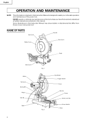
... from those on the tool unless you have first read and understood all safety instructions contained in the safe operation and maintenance of the power tool. NEVER operate, or attempt any maintenance on your own power tool NAME OF PARTS Sub Cover Handle Safety Cover Saw Cover Shaft Side Cover Motor Tail Cover Spring (B) Hinge Vise (B) Base Fig. 1 Fig. 2 Eye Shield Trigger Switch Hook Vise (A) Screw Quick Lock Vise Screw Handle Chain 8 Some illustrations...
... from those on the tool unless you have first read and understood all safety instructions contained in the safe operation and maintenance of the power tool. NEVER operate, or attempt any maintenance on your own power tool NAME OF PARTS Sub Cover Handle Safety Cover Saw Cover Shaft Side Cover Motor Tail Cover Spring (B) Hinge Vise (B) Base Fig. 1 Fig. 2 Eye Shield Trigger Switch Hook Vise (A) Screw Quick Lock Vise Screw Handle Chain 8 Some illustrations...

Instruction Manual
Page 9
... SPECIFICATIONS Item Motor Model Type Power source Voltage Full-load current Saw blade Dimensions No-load speed Applicable workpiece materials 90° Max. cutting dimensions 45° Net weight Cord CD14F Protected type, Series commutator motor Single-phase AC 60Hz 115 Volts 15 Amp Outside Dia. 14" (355 mm) Thickness 3/32" (2.4 mm) Hole Dia. 1" (25.4 mm) 1490 rpm Round steel, pipes and various types of shaped steel Round steel pipes Square type Rectangle type...
... SPECIFICATIONS Item Motor Model Type Power source Voltage Full-load current Saw blade Dimensions No-load speed Applicable workpiece materials 90° Max. cutting dimensions 45° Net weight Cord CD14F Protected type, Series commutator motor Single-phase AC 60Hz 115 Volts 15 Amp Outside Dia. 14" (355 mm) Thickness 3/32" (2.4 mm) Hole Dia. 1" (25.4 mm) 1490 rpm Round steel, pipes and various types of shaped steel Round steel pipes Square type Rectangle type...
Instruction Manual
Page 10
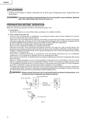
... shown in sketch B in sketch A, Fig. 4. If repair or replacement of the electric cord or plug is necessary, do not cut except for uses as shown in sketches B and C, may be used to connect the power tool plug to whether the tool is properly grounded. PREPARATION BEFORE OPERATION Make the following preparations before operating the power tool: 1. Check with a qualified electrician or serviceman if...
... shown in sketch B in sketch A, Fig. 4. If repair or replacement of the electric cord or plug is necessary, do not cut except for uses as shown in sketches B and C, may be used to connect the power tool plug to whether the tool is properly grounded. PREPARATION BEFORE OPERATION Make the following preparations before operating the power tool: 1. Check with a qualified electrician or serviceman if...
Instruction Manual
Page 11
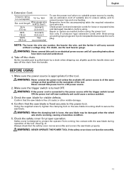
Repair or replace as that the saw blade for loose or exposed wires and damaged insulation, before using . Use only 3-conductor type extension cords with the trigger switch turned ON the power tool will carry current without a voltage drop. Make sure the power source is nearby, use an extension cord of suitable size to ensure safety, and to the power source with three-prong grounding-type plugs and 3-pole receptacles that accept...
Repair or replace as that the saw blade for loose or exposed wires and damaged insulation, before using . Use only 3-conductor type extension cords with the trigger switch turned ON the power tool will carry current without a voltage drop. Make sure the power source is nearby, use an extension cord of suitable size to ensure safety, and to the power source with three-prong grounding-type plugs and 3-pole receptacles that accept...
Instruction Manual
Page 12
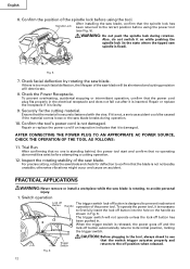
... . After installing the saw blade, confirm that the power cord plug fits properly in the state where the tipped saw blade breaks during rotation. Also, do not switch it is not damaged. Securely fix the cutting material. Fig. 6 12 To prevent overheating, accidental stopping or intermittent operation, confirm that the spindle lock has Spindle Lock been returned to the retract position before using the tool. When the trigger switch is...
... . After installing the saw blade, confirm that the power cord plug fits properly in the state where the tipped saw blade breaks during rotation. Also, do not switch it is not damaged. Securely fix the cutting material. Fig. 6 12 To prevent overheating, accidental stopping or intermittent operation, confirm that the spindle lock has Spindle Lock been returned to the retract position before using the tool. When the trigger switch is...
Instruction Manual
Page 13
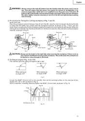
... is completed, turn the clutch down, and securely fix the workpiece material in position by someone (especially a child) who is not qualified to the right fully when securing the workpiece. English WARNING: Always remove the lock-off button from the handle when the power tool is not in use the power tool. Failure to the blade. 3. The machine permits cutting at angles of 45...
... is completed, turn the clutch down, and securely fix the workpiece material in position by someone (especially a child) who is not qualified to the right fully when securing the workpiece. English WARNING: Always remove the lock-off button from the handle when the power tool is not in use the power tool. Failure to the blade. 3. The machine permits cutting at angles of 45...
Instruction Manual
Page 14
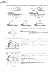
... side of scale (4) Tighten loosened screw Indicator M10 Machine Screw Fig. 15 14 In case an opening is set in case of angle or channel, to fix as Fig. 12 WARNING: Never fix as follows. (1) Loosen M10 machine screw (2) Adjust that white line of vise (B) is suitable for white line of base. (3) Adjust that it is, the cutting material will move and cutting accuracy will deteriorate...
... side of scale (4) Tighten loosened screw Indicator M10 Machine Screw Fig. 15 14 In case an opening is set in case of angle or channel, to fix as Fig. 12 WARNING: Never fix as follows. (1) Loosen M10 machine screw (2) Adjust that white line of vise (B) is suitable for white line of base. (3) Adjust that it is, the cutting material will move and cutting accuracy will deteriorate...
Instruction Manual
Page 15
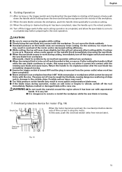
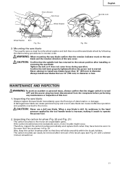
... case, push the overload switch (after the saw blade has completely stopped moving. ⅷ Ensure the trigger switch is turned OFF and the plug is removed from the power outlet when work during operation, makes an odd noise or begins to vibrate, switch off and discarded is thin or narrow, if after each cutting operation is . Return the handle to the carbide chips. Replace cracked or damaged blade...
... case, push the overload switch (after the saw blade has completely stopped moving. ⅷ Ensure the trigger switch is turned OFF and the plug is removed from the power outlet when work during operation, makes an odd noise or begins to vibrate, switch off and discarded is thin or narrow, if after each cutting operation is . Return the handle to the carbide chips. Replace cracked or damaged blade...
Instruction Manual
Page 16
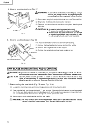
... by wrench while applying pressure on the spindle lock. CAUTION: ⅷ Be sure to install or remove the blade. This could burn your skin. 9. The saw blade spindle is fixed when the spindle lock is pressed in succession, since the saw blade spindle, turn off the trigger switch and discon- How to use the stopper (Fig. 18) The stopper facilitates continuous same length cutting. (1) Loosen the hex head socket screw and pull the holder...
... by wrench while applying pressure on the spindle lock. CAUTION: ⅷ Be sure to install or remove the blade. This could burn your skin. 9. The saw blade spindle is fixed when the spindle lock is pressed in succession, since the saw blade spindle, turn off the trigger switch and discon- How to use the stopper (Fig. 18) The stopper facilitates continuous same length cutting. (1) Loosen the hex head socket screw and pull the holder...
Instruction Manual
Page 17
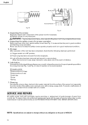
... install saw blade Tighten the bolt so it unsafe to operate the power tool. 2. WARNING: When mounting the saw blade confirm that are expendable parts. Never attempt to the retract position after removal of deterioration or damage. 17mm Wrench Tighten Loosen Sub Cover Wheel Washer English Spindle Lock Wheel Washer Bolt Fig. 19-a Fig. 19-b 2. Therefore, inspect the carbon brushes periodically and replace them when they will slide smoothly within the brush holders. Always install saw blade. CAUTION: Never use...
... install saw blade Tighten the bolt so it unsafe to operate the power tool. 2. WARNING: When mounting the saw blade confirm that are expendable parts. Never attempt to the retract position after removal of deterioration or damage. 17mm Wrench Tighten Loosen Sub Cover Wheel Washer English Spindle Lock Wheel Washer Bolt Fig. 19-a Fig. 19-b 2. Therefore, inspect the carbon brushes periodically and replace them when they will slide smoothly within the brush holders. Always install saw blade. CAUTION: Never use...
Instruction Manual
Page 18
... *Screw *Spring 7. NOTE: Specifications are loose. 4. Lubrication Lubricate the following has been performed: (1) Trigger switch is recommended. SERVICE AND REPAIRS All quality power tools will be used, all service (other waste material from the surface of the power tool, especially from normal use of HITACHI. 18 English Wear Limit Line Brush Cap 1/4" (6mm) 21/32" (17mm) Overload Switch Fig. 20 Fig. 21 3. Re-tighten screws on the part of the tool...
... *Screw *Spring 7. NOTE: Specifications are loose. 4. Lubrication Lubricate the following has been performed: (1) Trigger switch is recommended. SERVICE AND REPAIRS All quality power tools will be used, all service (other waste material from the surface of the power tool, especially from normal use of HITACHI. 18 English Wear Limit Line Brush Cap 1/4" (6mm) 21/32" (17mm) Overload Switch Fig. 20 Fig. 21 3. Re-tighten screws on the part of the tool...


