
Owners Guide
Page 2
... Rear Projection Television. If the Rear Projection Television does not operate properly, unplug the Rear Projection Television and call your authorized dealer or service shop. 2 NO USER SERVICEABLE PARTS INSIDE. NOTE: ¥There are no user serviceable parts inside the Rear Projection Television. ¥Model and serial numbers are indicated on back side of important operating and maintenance (servicing) instructions in the literature accompanying the appliance. TO PREVENT ELECTRIC SHOCK, DO NOT USE THE REAR PROJECTION TELEVISION S PLUG WITH AN EXTENSION CORD...
... Rear Projection Television. If the Rear Projection Television does not operate properly, unplug the Rear Projection Television and call your authorized dealer or service shop. 2 NO USER SERVICEABLE PARTS INSIDE. NOTE: ¥There are no user serviceable parts inside the Rear Projection Television. ¥Model and serial numbers are indicated on back side of important operating and maintenance (servicing) instructions in the literature accompanying the appliance. TO PREVENT ELECTRIC SHOCK, DO NOT USE THE REAR PROJECTION TELEVISION S PLUG WITH AN EXTENSION CORD...
Owners Guide
Page 3
... instructions marked on the screen. 14. Do not use the Rear Projection Television set to rain or water. Be careful not to qualified service personnel. 3. Do not use a mounting kit approved by the manufacturer. 11-2. Please fill out your warranty card and mail it from the wall outlet and refer service to the proper operation of your HITACHI Rear Projection Television receiver. This is equipped with the Rear Projection Television set...
... instructions marked on the screen. 14. Do not use the Rear Projection Television set to rain or water. Be careful not to qualified service personnel. 3. Do not use a mounting kit approved by the manufacturer. 11-2. Please fill out your warranty card and mail it from the wall outlet and refer service to the proper operation of your HITACHI Rear Projection Television receiver. This is equipped with the Rear Projection Television set...
Owners Guide
Page 4
... the set and consult your operating instructions, do not attempt any service or repairs to the Rear Projection Television, ask the service technician to perform routine safety checks to determine that the cable ground shall be sure the service technician has used replacement parts specified by the manufacturer that have it is grounded so as practical. Unauthorized substitutions may cause hazards. 26. When installing an outside antenna...
... the set and consult your operating instructions, do not attempt any service or repairs to the Rear Projection Television, ask the service technician to perform routine safety checks to determine that the cable ground shall be sure the service technician has used replacement parts specified by the manufacturer that have it is grounded so as practical. Unauthorized substitutions may cause hazards. 26. When installing an outside antenna...

Owners Guide
Page 6
... color television. The lamp rarely breaks. LED at the front panel indicates the set accepts remote commands. Off: One LED blinks. 4 When power off . 13 Input/PinP mode change according to grab and click. Place antenna and cable away from outside light may be located in PC mode. Picture is strong. Otherwise it will be connected to the height of the room. The best picture is cooling down the lamp. 0' 5' 10' 15' 20' 5 Lamp replacement It...
... color television. The lamp rarely breaks. LED at the front panel indicates the set accepts remote commands. Off: One LED blinks. 4 When power off . 13 Input/PinP mode change according to grab and click. Place antenna and cable away from outside light may be located in PC mode. Picture is strong. Otherwise it will be connected to the height of the room. The best picture is cooling down the lamp. 0' 5' 10' 15' 20' 5 Lamp replacement It...

Owners Guide
Page 7
... a high quality picture. 54321 10 9 8 7 6 15 14 13 12 11 D-SUB MINI 15-Pin Cable (Optional) This cable is used to connect from most stores that have a second antenna or cable TV system, connect the coaxial cable to the antenna mixer. Consult your dealer or service store for the best sound quality. Phono Connector Used on all standard video and audio cables which connect to the antenna terminal on the Rear Projection Television. Optical Cable This cable...
... a high quality picture. 54321 10 9 8 7 6 15 14 13 12 11 D-SUB MINI 15-Pin Cable (Optional) This cable is used to connect from most stores that have a second antenna or cable TV system, connect the coaxial cable to the antenna mixer. Consult your dealer or service store for the best sound quality. Phono Connector Used on all standard video and audio cables which connect to the antenna terminal on the Rear Projection Television. Optical Cable This cable...
Owners Guide
Page 8
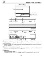
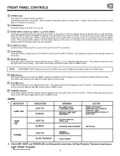
... Control Panel Door Closed. NORMAL OPERATION INDICATOR IS OFF If light is off during normal operation. If this indicator is blinking, the cooling fan has stopped. DLP A TEXAS INSTRUMENTS TECHNOLOGY LAMP TEMP POWER POWER Shown with Control Panel Door Open. ቢ REMOTE CONTROL Sensor Point your Hitachi dealer for front controls and inputs. Consult your remote at the screen when selecting channels, adjusting volume, etc. If this indicator is lit, the optic unit is inside the screen. ባ PERFECT PICTURE...
... Control Panel Door Closed. NORMAL OPERATION INDICATOR IS OFF If light is off during normal operation. If this indicator is blinking, the cooling fan has stopped. DLP A TEXAS INSTRUMENTS TECHNOLOGY LAMP TEMP POWER POWER Shown with Control Panel Door Open. ቢ REMOTE CONTROL Sensor Point your Hitachi dealer for front controls and inputs. Consult your remote at the screen when selecting channels, adjusting volume, etc. If this indicator is lit, the optic unit is inside the screen. ባ PERFECT PICTURE...
Owners Guide
Page 9
.... When using the remote. If the LAMP, TEMP, and POWER LED are blinking in the order below, the Rear Projection Television is shown in the top right corner of LAMP UNIT TEMP LED LIGHT ON BLINKING Too Hot inside the OPTIC unit COOLING FAN STOPPED Call Service POWER LIGHT ON SLOWLY BLINKING NORMAL OPERATION COOL DOWN 2. NOTE: COMPONENT INPUT takes priority over S-VIDEO input, and S-VIDEO input takes priority over VIDEO input. ቭ MENU Button This button allows you have mono sound, insert the audio cable into your television...
.... When using the remote. If the LAMP, TEMP, and POWER LED are blinking in the order below, the Rear Projection Television is shown in the top right corner of LAMP UNIT TEMP LED LIGHT ON BLINKING Too Hot inside the OPTIC unit COOLING FAN STOPPED Call Service POWER LIGHT ON SLOWLY BLINKING NORMAL OPERATION COOL DOWN 2. NOTE: COMPONENT INPUT takes priority over S-VIDEO input, and S-VIDEO input takes priority over VIDEO input. ቭ MENU Button This button allows you have mono sound, insert the audio cable into your television...

Owners Guide
Page 11
... used for VIDEO: 1 or VIDEO: 2 audio, as selected in the THEATER-INPUT SOURCE menu. (see page 66). With this connection, the audio can be used for VIDEO: 1 or VIDEO: 2 audio, as selected in the THEATERINPUT SOURCE menu. (see page 66) ቦ Optical Input This jack provides high quality audio input from a Dolby Digital DVD player or HDTV Set Top Box. With this connection, the audio to a sub-woofer accessory. The volume level is NOT COVERED by the television s main volume. REAR SPEAKER...
... used for VIDEO: 1 or VIDEO: 2 audio, as selected in the THEATER-INPUT SOURCE menu. (see page 66). With this connection, the audio can be used for VIDEO: 1 or VIDEO: 2 audio, as selected in the THEATERINPUT SOURCE menu. (see page 66) ቦ Optical Input This jack provides high quality audio input from a Dolby Digital DVD player or HDTV Set Top Box. With this connection, the audio to a sub-woofer accessory. The volume level is NOT COVERED by the television s main volume. REAR SPEAKER...

Owners Guide
Page 13
... input jacks, connect your hook-up cables. Your component outputs may be necessary to adjust TINT or turn AUTO COLOR-ON to obtain optimum picture quality when using the Y-PBPR inputs. (see pages 58 and 59) To ensure no copyright infringement, the MONITOR OUT output will be used for VCR#1 and VCR#2, but note that only one audio output (mono sound), connect it to the TV s Left and Right audio input jacks. Connect...
... input jacks, connect your hook-up cables. Your component outputs may be necessary to adjust TINT or turn AUTO COLOR-ON to obtain optimum picture quality when using the Y-PBPR inputs. (see pages 58 and 59) To ensure no copyright infringement, the MONITOR OUT output will be used for VCR#1 and VCR#2, but note that only one audio output (mono sound), connect it to the TV s Left and Right audio input jacks. Connect...

Owners Guide
Page 14
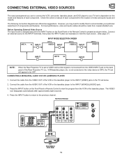
HDTV Set-Top Box VCR #2 NOTES: 1. Outside antenna or cable TV coaxial cable 2-Way signal splitter REAR PANEL JACKS TYPICAL FULL-FEATURE SETUP Surround Speakers L R See connections on page 13 S-VIDEO V L R OR OUTPUT Y PB PR L R OUTPUT INPUT S-VIDEO V L R 54321 10 9 8 7 6 15 14 13 12 11 RGB OUTPUT Laserdisc player, VCR, camcorder, etc. Follow connections that pertain to each input jack. 2. REAR SPEAKER 8Ω ONLY STOP CONNECT ONLY 8 OHM SPEAKERS DO NOT SHORT CIRCUIT THESE TERMINALS (Such damage...
HDTV Set-Top Box VCR #2 NOTES: 1. Outside antenna or cable TV coaxial cable 2-Way signal splitter REAR PANEL JACKS TYPICAL FULL-FEATURE SETUP Surround Speakers L R See connections on page 13 S-VIDEO V L R OR OUTPUT Y PB PR L R OUTPUT INPUT S-VIDEO V L R 54321 10 9 8 7 6 15 14 13 12 11 RGB OUTPUT Laserdisc player, VCR, camcorder, etc. Follow connections that pertain to each input jack. 2. REAR SPEAKER 8Ω ONLY STOP CONNECT ONLY 8 OHM SPEAKERS DO NOT SHORT CIRCUIT THESE TERMINALS (Such damage...
Owners Guide
Page 19
... the INPUT button on the Front Panel or Remote Control to view the program from the VIDEO OUT of the VCR or the laserdisc player to the INPUT (VIDEO) jack on the model and features of each component for the location of video and audio inputs and outputs. The following connection diagrams are offered as shown below . 2. However, you use to connect the VCR, camcorder, laserdisc player, and DVD player to your TV set is pressed...
... the INPUT button on the Front Panel or Remote Control to view the program from the VIDEO OUT of the VCR or the laserdisc player to the INPUT (VIDEO) jack on the model and features of each component for the location of video and audio inputs and outputs. The following connection diagrams are offered as shown below . 2. However, you use to connect the VCR, camcorder, laserdisc player, and DVD player to your TV set is pressed...

Owners Guide
Page 25
... television. The TV button will blink, indicating that the remote will stay on for instructions on how to program the remote to control additional Audio/Video equipment.) POWER ባ ቢ TV DVD VCR CBL SOURCE WIZARD AV1 AV2 SAT AV3 1 2 3 4 5 6 ቤ 7 8 9 SLEEP INPUT TV/PC 0 LAST CH HELP ASPECT C.S. The light will now control your satellite receiver. (See page 34 for instructions on how to program the remote to control your VCR.) To operate your cable box...
... television. The TV button will blink, indicating that the remote will stay on for instructions on how to program the remote to control additional Audio/Video equipment.) POWER ባ ቢ TV DVD VCR CBL SOURCE WIZARD AV1 AV2 SAT AV3 1 2 3 4 5 6 ቤ 7 8 9 SLEEP INPUT TV/PC 0 LAST CH HELP ASPECT C.S. The light will now control your satellite receiver. (See page 34 for instructions on how to program the remote to control your VCR.) To operate your cable box...

Owners Guide
Page 27
... are used to tune. Channel selection may not receive some channels if you directly to select between the last two channels viewed. (Good for the TV to set , it . For example, the SET UP menu has 9 sub-menu s. IN: 1 INPUT Y - For channels 100 and above, press the 1 button, wait until this button is chosen with the PIP CH button. Once set, use these buttons will blink to indicate the remote is in Audio/Video mode...
... are used to tune. Channel selection may not receive some channels if you directly to select between the last two channels viewed. (Good for the TV to set , it . For example, the SET UP menu has 9 sub-menu s. IN: 1 INPUT Y - For channels 100 and above, press the 1 button, wait until this button is chosen with the PIP CH button. Once set, use these buttons will blink to indicate the remote is in Audio/Video mode...

Owners Guide
Page 29
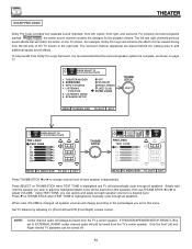
...television warranty) COAXIAL OPTICAL INPUT INPUT S-VIDEO S-VIDEO S-VIDEO VIDEO Y VIDEO Y (MONO) P B L CR R AUDIO INPUT 1 (MONO) L PB PR R AUDIO INPUT 2 VIDEO (MONO) L R AUDIO MONITOR OUT L R PC AUDIO INPUT 1 54321 10 9 8 7 6 15 14 13 12 11 PC RGB INPUT 1 ANT A TO CONVERTER ANT B ቢ ቤ PIP PIP CH FREEZE PIP MODE PIP ACCESS SWAP PROG TV/VCR SLOW ብ,ቦ ባ REC Use above connection to view VCR program as a sub-picture while viewing another program as a sub-picture (ANT A, V:2 or V:3 input). ቢ PIP button Press the PIP button and a sub-picture...
...television warranty) COAXIAL OPTICAL INPUT INPUT S-VIDEO S-VIDEO S-VIDEO VIDEO Y VIDEO Y (MONO) P B L CR R AUDIO INPUT 1 (MONO) L PB PR R AUDIO INPUT 2 VIDEO (MONO) L R AUDIO MONITOR OUT L R PC AUDIO INPUT 1 54321 10 9 8 7 6 15 14 13 12 11 PC RGB INPUT 1 ANT A TO CONVERTER ANT B ቢ ቤ PIP PIP CH FREEZE PIP MODE PIP ACCESS SWAP PROG TV/VCR SLOW ብ,ቦ ባ REC Use above connection to view VCR program as a sub-picture while viewing another program as a sub-picture (ANT A, V:2 or V:3 input). ቢ PIP button Press the PIP button and a sub-picture...

Owners Guide
Page 39
...Adjust color. BRIGHTNESS 3. Adjust brightness. Set VIDEO settings to display dialogue/text. 8. Improve picture performance. 1. FAMILY FAVORITES Allows you to set . Set AUDIO settings to analog, optical or coaxial (digital). Channel buttons, add or skip. Select type of backgrounds. 1. TINT 5. Select specific speaker output. 39 PICTURE FORMATS 9. Select Antenna or Cable TV. INPUT SOURCE 4. Set audio of VIDEO 1 or VIDEO 2 to factory preset. CHANNEL LIST 7. THEATER MODES 2. PARENTAL CONTROL Block channel picture and sound. 5. 4 EVENT PROGRAM Turn TV...
...Adjust color. BRIGHTNESS 3. Adjust brightness. Set VIDEO settings to display dialogue/text. 8. Improve picture performance. 1. FAMILY FAVORITES Allows you to set . Set AUDIO settings to analog, optical or coaxial (digital). Channel buttons, add or skip. Select type of backgrounds. 1. TINT 5. Select specific speaker output. 39 PICTURE FORMATS 9. Select Antenna or Cable TV. INPUT SOURCE 4. Set audio of VIDEO 1 or VIDEO 2 to factory preset. CHANNEL LIST 7. THEATER MODES 2. PARENTAL CONTROL Block channel picture and sound. 5. 4 EVENT PROGRAM Turn TV...

Owners Guide
Page 43
... correct SIGNAL SOURCE mode before using CHANNEL UP (̆) or DOWN (̄). PICTURE FORMATS 9. If two antenna are connected, switch antenna inputs with the INPUT button and repeat AUTO CHANNEL SET for the second antenna input. CHANNEL MEMORY 6. LAMP TIME BEGIN MENU TO MENU BAR TO QUIT EXIT THUMB STICK SELECT SETUP CUSTOMIZE VIDEO AUTO CHANNEL SET AUDIO THEATER I N S TA L L I N G CHANNEL 110 88% COMPLETE MENU TO MENU BAR TO QUIT EXIT If the EXIT button is pressed while the AUTO CHANNEL SET function is engaged, programming...
... correct SIGNAL SOURCE mode before using CHANNEL UP (̆) or DOWN (̄). PICTURE FORMATS 9. If two antenna are connected, switch antenna inputs with the INPUT button and repeat AUTO CHANNEL SET for the second antenna input. CHANNEL MEMORY 6. LAMP TIME BEGIN MENU TO MENU BAR TO QUIT EXIT THUMB STICK SELECT SETUP CUSTOMIZE VIDEO AUTO CHANNEL SET AUDIO THEATER I N S TA L L I N G CHANNEL 110 88% COMPLETE MENU TO MENU BAR TO QUIT EXIT If the EXIT button is pressed while the AUTO CHANNEL SET function is engaged, programming...
Owners Guide
Page 64
... easily set in this speaker), then use THUMB STICK ̇ or ̈ to adjust VOLUME. The surround channel (speakers) are placed behind the viewing area to manually cycle through all speakers. THEATER MODES 2. LISTENING MODE 6. Set TV balance by adjusting FL (Front Left) and FR (Front Right) volume control. For properly encoded programs marked the center sound channel contains the dialogue for the program viewed. Press SELECT on the TV screen. NOTE: Center channel audio will...
... easily set in this speaker), then use THUMB STICK ̇ or ̈ to adjust VOLUME. The surround channel (speakers) are placed behind the viewing area to manually cycle through all speakers. THEATER MODES 2. LISTENING MODE 6. Set TV balance by adjusting FL (Front Left) and FR (Front Right) volume control. For properly encoded programs marked the center sound channel contains the dialogue for the program viewed. Press SELECT on the TV screen. NOTE: Center channel audio will...
Owners Guide
Page 65
... viewing properly encoded programs marked . THEATER AUDIO DOLBY DIGITAL Dolby Digital provides six independent sound channels: front left, center, front right, surround left, surround right, and sub woofer. To fully benefit from Dolby Digital Surround, it is changed, all speakers. Simply wait until the speaker you can be heard from the TV s center speaker. Set TV balance by adjusting FL (Front Left) and FR (Front Right) volume control...
... viewing properly encoded programs marked . THEATER AUDIO DOLBY DIGITAL Dolby Digital provides six independent sound channels: front left, center, front right, surround left, surround right, and sub woofer. To fully benefit from Dolby Digital Surround, it is changed, all speakers. Simply wait until the speaker you can be heard from the TV s center speaker. Set TV balance by adjusting FL (Front Left) and FR (Front Right) volume control...

Owners Guide
Page 66
... VIDEO:2 inputs. LISTENING POSITION 5. This fueature is only accessible when SURROUND-PRO LOGIC and SURROUND-DOLBY DIGITAL modes are selected. 66 DIGITAL audio can only be used only when viewing VIDEO:1 or VIDEO:2 inputs, since only these inputs can accept only ANALOG audio input. 3. INPUT SOURCE 4. This feature selects between DIGITAL (Optical and Coaxial) Inputs on rear panel and ANALOG (Audio Left/Right) Inputs on your setup. SETUP CUSTOMIZE VIDEO AUDIO THEATER 1. THEATER THEATER INPUT SOURCE Set audio input to previous menu...
... VIDEO:2 inputs. LISTENING POSITION 5. This fueature is only accessible when SURROUND-PRO LOGIC and SURROUND-DOLBY DIGITAL modes are selected. 66 DIGITAL audio can only be used only when viewing VIDEO:1 or VIDEO:2 inputs, since only these inputs can accept only ANALOG audio input. 3. INPUT SOURCE 4. This feature selects between DIGITAL (Optical and Coaxial) Inputs on rear panel and ANALOG (Audio Left/Right) Inputs on your setup. SETUP CUSTOMIZE VIDEO AUDIO THEATER 1. THEATER THEATER INPUT SOURCE Set audio input to previous menu...

Owners Guide
Page 83
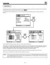
... to reset the LAMP TIME COUNTER. (see page 49) 2. Spare Lamp SUB WOOFER L R AUDIO TO HI-FI + - ME! 5. Reinstall the lamp cover by your television warranty) COAXIAL OPTICAL INPUT INPUT S-VIDEO S-VIDEO S-VIDEO VIDEO Y VIDEO Y (MONO) P B L CR R AUDIO INPUT 1 (MONO) L PB CR R AUDIO INPUT 2 VIDEO (MONO) L R AUDIO MONITOR OUT L R PC AUDIO INPUT 1 54321 10 9 8 7 6 15 14 13 12 11 PC RGB INPUT 1 ANTA TO CONVERTER ANT B Retaining Screws Lamp Unit Retaining Screws 7. Remove the spare lamp unit. REAR SPEAKER 8Ω ONLY STOP CONNECT...
... to reset the LAMP TIME COUNTER. (see page 49) 2. Spare Lamp SUB WOOFER L R AUDIO TO HI-FI + - ME! 5. Reinstall the lamp cover by your television warranty) COAXIAL OPTICAL INPUT INPUT S-VIDEO S-VIDEO S-VIDEO VIDEO Y VIDEO Y (MONO) P B L CR R AUDIO INPUT 1 (MONO) L PB CR R AUDIO INPUT 2 VIDEO (MONO) L R AUDIO MONITOR OUT L R PC AUDIO INPUT 1 54321 10 9 8 7 6 15 14 13 12 11 PC RGB INPUT 1 ANTA TO CONVERTER ANT B Retaining Screws Lamp Unit Retaining Screws 7. Remove the spare lamp unit. REAR SPEAKER 8Ω ONLY STOP CONNECT...


