Owners Guide
Page 1
PROJECTION COLOR TV Operating Guide for energy efficiency. has determined that this product meets the ENERGY STAR® guidelines for 51F520, 57F520 IMPORTANT SAFETY INSTRUCTIONS 2-3 FIRST TIME USE ...4-18 THE REMOTE CONTROL 19-32 ON-SCREEN DISPLAY...33-65 CARE OF YOUR HITACHI TELEVISION 66 RECEPTION PROBLEMS...67 USEFUL INFORMATION / INDEX 68-71 57" DISASSEMBLY/ASSEMBLY INSTRUCTIONS 72-74 INDEX ...75 As an ENERGY STAR® Partner, Hitachi, Ltd.
PROJECTION COLOR TV Operating Guide for energy efficiency. has determined that this product meets the ENERGY STAR® guidelines for 51F520, 57F520 IMPORTANT SAFETY INSTRUCTIONS 2-3 FIRST TIME USE ...4-18 THE REMOTE CONTROL 19-32 ON-SCREEN DISPLAY...33-65 CARE OF YOUR HITACHI TELEVISION 66 RECEPTION PROBLEMS...67 USEFUL INFORMATION / INDEX 68-71 57" DISASSEMBLY/ASSEMBLY INSTRUCTIONS 72-74 INDEX ...75 As an ENERGY STAR® Partner, Hitachi, Ltd.
Owners Guide
Page 3
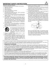
...sure the antenna system is damaged, liquid has been spilled or objects have fallen into position. Reverse engineering or disassembly is provided to call 1-800-HITACHI. 3 This product contains lead. For more rapidly than the other. ing-type plug. If the provided plug...70-1984, provides information with moving the cart/apparatus combination to television receivers. For product recycling and disposal information, contact your HITACHI Factory Warranty. • PUBLIC VIEWING OF COPYRIGHTED MATERIAL Public viewing of programs broadcast by TV stations and cable companies, as ...
...sure the antenna system is damaged, liquid has been spilled or objects have fallen into position. Reverse engineering or disassembly is provided to call 1-800-HITACHI. 3 This product contains lead. For more rapidly than the other. ing-type plug. If the provided plug...70-1984, provides information with moving the cart/apparatus combination to television receivers. For product recycling and disposal information, contact your HITACHI Factory Warranty. • PUBLIC VIEWING OF COPYRIGHTED MATERIAL Public viewing of programs broadcast by TV stations and cable companies, as ...
Owners Guide
Page 72
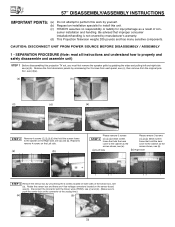
...by yourself. (b) Request an installation specialist to the cabinet on the Right side, see (a) and (b). CAUTION: DISCONNECT UNIT FROM POWER SOURCE BEFORE DISASSEMBLY / ASSEMBLY 1 - Repeat to remove 4 screws on the Left side. (a) (b) Please remove 3 screws STEP 3 below screen frame that hold... the screen frame to install this unit. (c) HITACHI assumes no responsibility or liability for injury/damage as the arrows shows, see (a). (a) Left Side Please remove 3 screws below screen frame that...
...by yourself. (b) Request an installation specialist to the cabinet on the Right side, see (a) and (b). CAUTION: DISCONNECT UNIT FROM POWER SOURCE BEFORE DISASSEMBLY / ASSEMBLY 1 - Repeat to remove 4 screws on the Left side. (a) (b) Please remove 3 screws STEP 3 below screen frame that hold... the screen frame to install this unit. (c) HITACHI assumes no responsibility or liability for injury/damage as the arrows shows, see (a). (a) Left Side Please remove 3 screws below screen frame that...

Owners Guide
Page 73
... any type of impact that is separated, the top portion weights 45 lbs. Remove top portion by grabbing the bottom corner of these components. 57" DISASSEMBLY/ASSEMBLY INSTRUCTIONS 1 - SEPARATION PROCEDURE CONTINUED STEP 4 Cont. (c) (d) STEP 5 Remove the joint connector bolts from the back side of the TV set only the top 4 screws...
... any type of impact that is separated, the top portion weights 45 lbs. Remove top portion by grabbing the bottom corner of these components. 57" DISASSEMBLY/ASSEMBLY INSTRUCTIONS 1 - SEPARATION PROCEDURE CONTINUED STEP 4 Cont. (c) (d) STEP 5 Remove the joint connector bolts from the back side of the TV set only the top 4 screws...

Owners Guide
Page 74
RE-ASSEMBLY PROCEDURE STEP 8 To re-assemble the set, lift the top portion and align onto the bottom cabinet. pletes the Disassembly and Assembly instructions. (a) (b) (c) 74 STEP 10 Re-install the top (4) four screws into the lower rear cover, see (c). Repeat to re-install 4 ... 3 screws below screen frame that hold the back cover to the cabinet as the arrows shows. (b) Right Side STEP 14 Re-install both of the disassembly. Re-install the sensor box, see (b). (a) (b) STEP 12 Re-install 4 screws that hold the screen frame to the sensor board, see (a) and (b). This...
RE-ASSEMBLY PROCEDURE STEP 8 To re-assemble the set, lift the top portion and align onto the bottom cabinet. pletes the Disassembly and Assembly instructions. (a) (b) (c) 74 STEP 10 Re-install the top (4) four screws into the lower rear cover, see (c). Repeat to re-install 4 ... 3 screws below screen frame that hold the back cover to the cabinet as the arrows shows. (b) Right Side STEP 14 Re-install both of the disassembly. Re-install the sensor box, see (b). (a) (b) STEP 12 Re-install 4 screws that hold the screen frame to the sensor board, see (a) and (b). This...

Owners Guide
Page 75
... 52 Closed Captions Analog Captions 63 Color Management 38 Color Decoding 39 Color Temperature 37 Color 37 Contrast 37 Convergence (see Magic Focus) D Date 52 Disassembly/Assembly Instructions (57 72-74 E Event Timer 54 F Freeze Button 20 G Guide Button on Remote 23 H HDMI 10, 11, 17 I Inputs Button 22 L Language Menu...
... 52 Closed Captions Analog Captions 63 Color Management 38 Color Decoding 39 Color Temperature 37 Color 37 Contrast 37 Convergence (see Magic Focus) D Date 52 Disassembly/Assembly Instructions (57 72-74 E Event Timer 54 F Freeze Button 20 G Guide Button on Remote 23 H HDMI 10, 11, 17 I Inputs Button 22 L Language Menu...
