TouchSmart 9100 Stand - HP Business PC
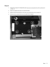
TouchSmart 9100 Stand
View Results Below
Free HP TouchSmart 9100 manuals!
Problems with HP TouchSmart 9100?
Ask a Question
Free HP TouchSmart 9100 manuals!
Problems with HP TouchSmart 9100?
Ask a Question
Related Manual Pages


Similar Questions

Putting Stand Back On An Iq500
I need to put the stand back on my IQ 500 and can't find a video or any instructions on how to do th...
I need to put the stand back on my IQ 500 and can't find a video or any instructions on how to do th...
(Posted by sissy6224 8 years ago)

How To Put Stand Of Hp Touchsmart Down
(Posted by qsralp 9 years ago)
What Base Stand Will Fit This Computer
oem stand for this computer is dicontinued and i need a stand
oem stand for this computer is dicontinued and i need a stand
(Posted by shanembailey 10 years ago)