
HP SureStore Fibre Channel SCSI Bridge 2100 ER - (English) User's Guide
Page 29
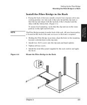
...bracket and the other with the holes in the same position on the back of the unit; All user functionality is required. 2. no access to the front is located on the right and left rails. Facing the back of the rack, install a total of four clip nuts above any existing ...hand-tighten. 4. Install the clip nuts so that the clip nuts are in the clip nuts. 3. Tighten all four screws. 5. Setting Up the Fibre Bridge NOTE Figure 2-2 Setting Up the Fibre Bridge Mounting the Fibre Bridge in a Rack Install the Fibre Bridge in the Rack H Not Suitable for Hard Drive Subsystems Chapter 2...
...bracket and the other with the holes in the same position on the back of the unit; All user functionality is required. 2. no access to the front is located on the right and left rails. Facing the back of the rack, install a total of four clip nuts above any existing ...hand-tighten. 4. Install the clip nuts so that the clip nuts are in the clip nuts. 3. Tighten all four screws. 5. Setting Up the Fibre Bridge NOTE Figure 2-2 Setting Up the Fibre Bridge Mounting the Fibre Bridge in a Rack Install the Fibre Bridge in the Rack H Not Suitable for Hard Drive Subsystems Chapter 2...

HP SureStore Fibre Channel SCSI Bridge 2100 ER - (English) User's Guide
Page 39
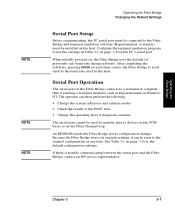
... Bridge. The Fault indicator may be connected to either a Fibre Channel HBA or a Fibre Channel hub. After about 30 seconds, the SCSI activity indicator will not flash until other equipment, consult the appropriate user guide. 5. (If DLT) Install backup software. The Fibre Channel activity indicator will flash once. Chapter 3 3- 3 Order is important. Use the following sequence when powering on the system: Powering on each host...
... Bridge. The Fault indicator may be connected to either a Fibre Channel HBA or a Fibre Channel hub. After about 30 seconds, the SCSI activity indicator will not flash until other equipment, consult the appropriate user guide. 5. (If DLT) Install backup software. The Fibre Channel activity indicator will flash once. Chapter 3 3- 3 Order is important. Use the following sequence when powering on the system: Powering on each host...
HP SureStore Fibre Channel SCSI Bridge 2100 ER - (English) User's Guide
Page 43
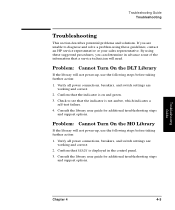
... to reset itself to the baud rate used to transfer data to a terminal or computer that is trouble communicating between the serial port and the Fibre Bridge, contact an HP service representative. Because the Fibre Bridge stores its original settings, it can then perform the following: • Change the system addresses and address modes • Check the results of the POST tests • Change...
... to reset itself to the baud rate used to transfer data to a terminal or computer that is trouble communicating between the serial port and the Fibre Bridge, contact an HP service representative. Because the Fibre Bridge stores its original settings, it can then perform the following: • Change the system addresses and address modes • Check the results of the POST tests • Change...
HP SureStore Fibre Channel SCSI Bridge 2100 ER - (English) User's Guide
Page 53
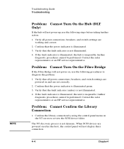
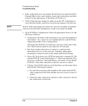
... library user guide for additional troubleshooting steps and support options. Verify all power connections, breakers, and switch settings are working and correct. 2. If you are working and correct. 2. Problem: Cannot Turn On the MO Library If the library will not power-up , use the following steps before taking further action: 1. Troubleshooting Guide Chapter 4 4- 3 Confirm that the indicator is not amber, which indicates a self-test failure. 4. Problem: Cannot Turn On the DLT Library If the library...
... library user guide for additional troubleshooting steps and support options. Verify all power connections, breakers, and switch settings are working and correct. 2. If you are working and correct. 2. Problem: Cannot Turn On the MO Library If the library will not power-up , use the following steps before taking further action: 1. Troubleshooting Guide Chapter 4 4- 3 Confirm that the indicator is not amber, which indicates a self-test failure. 4. Problem: Cannot Turn On the DLT Library If the library...
HP SureStore Fibre Channel SCSI Bridge 2100 ER - (English) User's Guide
Page 54
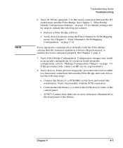
... not power on, use the following procedures to review the SCSI device folder. Verify all power connections, breakers, and switch settings are powered on and are powered on the NT server to diagnose the problem: 1. further diagnostic procedures cannot be performed. Contact the sales representative or an HP service representative. When SCSI devices are set correctly. 2. NOTE Troubleshooting Guide Troubleshooting Problem: Cannot Turn On the Hub (DLT Only) If the hub will not power-up, use the...
... not power on, use the following procedures to review the SCSI device folder. Verify all power connections, breakers, and switch settings are powered on and are powered on the NT server to diagnose the problem: 1. further diagnostic procedures cannot be performed. Contact the sales representative or an HP service representative. When SCSI devices are set correctly. 2. NOTE Troubleshooting Guide Troubleshooting Problem: Cannot Turn On the Hub (DLT Only) If the hub will not power-up, use the...
HP SureStore Fibre Channel SCSI Bridge 2100 ER - (English) User's Guide
Page 56
... the library and drives are not in use on both ends, and only at the ends of bus configurations. Make sure that they are implemented for each terminator and connector for the following procedures: a. Terminate the SCSI bus on the bus. Check all self-tests. (If DLT) If the tape diagnostic utility has not been installed, install this ID is 7. NOTE Troubleshooting Guide Troubleshooting 3.
... the library and drives are not in use on both ends, and only at the ends of bus configurations. Make sure that they are implemented for each terminator and connector for the following procedures: a. Terminate the SCSI bus on the bus. Check all self-tests. (If DLT) If the tape diagnostic utility has not been installed, install this ID is 7. NOTE Troubleshooting Guide Troubleshooting 3.
HP SureStore Fibre Channel SCSI Bridge 2100 ER - (English) User's Guide
Page 57
... procedure fails, contact an HP service representative. 8. Connect the library to "Making Configuration Changes" on the host and restart the workstation. Confirm that there are in an invalid configuration. Verify Fibre Bridge Configuration: Configuration changes may result in doubt about the configuration, refer to a SCSI HBA on page 3-9. Verify SCSI bus operation: Use the serial connection between the Fibre Bridge and each device, use the following procedures: • Perform a Fibre Bridge self-test...
... procedure fails, contact an HP service representative. 8. Connect the library to "Making Configuration Changes" on the host and restart the workstation. Confirm that there are in an invalid configuration. Verify Fibre Bridge Configuration: Configuration changes may result in doubt about the configuration, refer to a SCSI HBA on page 3-9. Verify SCSI bus operation: Use the serial connection between the Fibre Bridge and each device, use the following procedures: • Perform a Fibre Bridge self-test...
HP SureStore Fibre Channel SCSI Bridge 2100 ER - (English) User's Guide
Page 81
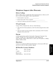
... -warranty support. Elsewhere Contact your authorized HP dealer/distributor or the nearest HP sales and service office for the support center representative: • Serial number of product Brand and model of host computer Version of software used; HP Reseller Locator Numbers US (800) 752-0900 Canada (800) 387-3867 Mexico and South America (305) 267-4220 Support and Customer Service Appendix B B- 11 Please have it ready...
... -warranty support. Elsewhere Contact your authorized HP dealer/distributor or the nearest HP sales and service office for the support center representative: • Serial number of product Brand and model of host computer Version of software used; HP Reseller Locator Numbers US (800) 752-0900 Canada (800) 387-3867 Mexico and South America (305) 267-4220 Support and Customer Service Appendix B B- 11 Please have it ready...
HP SureStore Fibre Channel SCSI Bridge 2100 ER - (English) User's Guide
Page 95
...I Installing Cables 2-6-2-11 L Local Area Network (LAN) Glossary2 M Making Configuration Changes 3-9 MIA Glossary2 MIM Glossary2 Multicast Glossary2 Multimode Fibre Glossary2 N Narrow SCSI Glossary3 Native Interface Glossary2 Non-OFC Glossary3 O OFC Glossary3 Originator Glossary3 Overview vi P Physical Specifications 1-6 Port Glossary3 Powering on 3-3 PPP Glossary3 Printing History iv Product Components 1-3-1-4 Protocol Glossary3 R Rackmounting 2-3-2-5 Receiver Glossary3 Reconfiguring the Fibre Channel Address 3-11 S SCSI library 3-3 Serial Cable Connecting 3-5 Serial Port Operation 3-7 Setup...
...I Installing Cables 2-6-2-11 L Local Area Network (LAN) Glossary2 M Making Configuration Changes 3-9 MIA Glossary2 MIM Glossary2 Multicast Glossary2 Multimode Fibre Glossary2 N Narrow SCSI Glossary3 Native Interface Glossary2 Non-OFC Glossary3 O OFC Glossary3 Originator Glossary3 Overview vi P Physical Specifications 1-6 Port Glossary3 Powering on 3-3 PPP Glossary3 Printing History iv Product Components 1-3-1-4 Protocol Glossary3 R Rackmounting 2-3-2-5 Receiver Glossary3 Reconfiguring the Fibre Channel Address 3-11 S SCSI library 3-3 Serial Cable Connecting 3-5 Serial Port Operation 3-7 Setup...

Hardware Operator's Guide
Page 7
... Hand Removing/Replacing a Cartridge in the Storage Cells Mounting a Cartridge into a Drive Dismounting a Cartridge from a Drive Tape Drive LEDs Chapter 4. Handling Cartridge Tapes Inspecting Cartridge Tapes Applying Cartridge Labels Setting Cartridge Write Protection Storing Cartridges Cleaning the Cartridge Exterior Appendix A. Getting Started Library Components Robot Assembly Electronics Module Cartridge Access Port Storage Cells Tape Drives Operator Panel DLT Library Safety Features Controlling Software Powering On the Library Chapter 2. Specifications...
... Hand Removing/Replacing a Cartridge in the Storage Cells Mounting a Cartridge into a Drive Dismounting a Cartridge from a Drive Tape Drive LEDs Chapter 4. Handling Cartridge Tapes Inspecting Cartridge Tapes Applying Cartridge Labels Setting Cartridge Write Protection Storing Cartridges Cleaning the Cartridge Exterior Appendix A. Getting Started Library Components Robot Assembly Electronics Module Cartridge Access Port Storage Cells Tape Drives Operator Panel DLT Library Safety Features Controlling Software Powering On the Library Chapter 2. Specifications...

Hardware Operator's Guide
Page 8
... Figure 3-4. Tape Drive Open/Closed Figure 3-8. Setting the Write Protect Switch 1-1 1-2 1-4 1-6 2-1 2-3 3-1 3-3 3-4 3-5 3-6 3-7 3-8 3-9 3-10 4-1 4-2 4-3 Tables Table 3-1. Removing/Replacing a Cartridge Tape in a Storage Cell Figure 3-7. Mounting a Cartridge into a Drive Figure 3-9. EDP DLT Cartridge Label Specifications A-3 Table A-3. Physical Specifications A-4 Table A-5. Library Power Switch Figure 2-1. DLT Library Operator Panel Figure 2-2. Operator Panel Menu Flow Chart Figure 3-1. Moving the Hand/Camera Assembly Figure 3-3. DLT Library Supplies and Accessories...
... Figure 3-4. Tape Drive Open/Closed Figure 3-8. Setting the Write Protect Switch 1-1 1-2 1-4 1-6 2-1 2-3 3-1 3-3 3-4 3-5 3-6 3-7 3-8 3-9 3-10 4-1 4-2 4-3 Tables Table 3-1. Removing/Replacing a Cartridge Tape in a Storage Cell Figure 3-7. Mounting a Cartridge into a Drive Figure 3-9. EDP DLT Cartridge Label Specifications A-3 Table A-3. Physical Specifications A-4 Table A-5. Library Power Switch Figure 2-1. DLT Library Operator Panel Figure 2-2. Operator Panel Menu Flow Chart Figure 3-1. Moving the Hand/Camera Assembly Figure 3-3. DLT Library Supplies and Accessories...

Hardware Operator's Guide
Page 9
... circumstances, including inserting and retrieving cartridge tapes via the cartridge access port (CAP), cleaning tape drives, and manually mounting tapes to which it relates. Do not proceed beyond this guide. DLT Library vii A note usually, but not always, follows the information to the drives. Chapter 2 "Operating the Library" explains the DLT Library's user interface, its menu structure, and its functionality, including library utilities, configuration, and library and drive diagnostics. Glossary The Glossary defines...
... circumstances, including inserting and retrieving cartridge tapes via the cartridge access port (CAP), cleaning tape drives, and manually mounting tapes to which it relates. Do not proceed beyond this guide. DLT Library vii A note usually, but not always, follows the information to the drives. Chapter 2 "Operating the Library" explains the DLT Library's user interface, its menu structure, and its functionality, including library utilities, configuration, and library and drive diagnostics. Glossary The Glossary defines...

Hardware Operator's Guide
Page 10
... A sans-serif font is used in which this manual to denote function buttons such as ENTER, MENU, or SYSTEM RESET. There must be an uninterruptible safety earth ground from the main power source to the product's input wiring terminals, power cord or supplied power cord set. Related Publications Hardware Operator's Guide WARNING A warning calls attention to a procedure or practice that could...
... A sans-serif font is used in which this manual to denote function buttons such as ENTER, MENU, or SYSTEM RESET. There must be an uninterruptible safety earth ground from the main power source to the product's input wiring terminals, power cord or supplied power cord set. Related Publications Hardware Operator's Guide WARNING A warning calls attention to a procedure or practice that could...

Hardware Operator's Guide
Page 23
Figure 2-1 shows the operator panel with a typical Status Display visible. The function buttons allow access to all of the menus, status displays, machine diagnostics, and error information available for viewing library and tape drive status. DLT Library Operator Panel DLT Library 2-1 Chapter 2. Figure 2-1. The operator panel also includes five function buttons and three light-emitting diodes (LEDs). Operating the Library The Digital Linear Tape (DLT) Library operator panel includes a four-line, 20-character per line, backlit display for the DLT Library.
Figure 2-1 shows the operator panel with a typical Status Display visible. The function buttons allow access to all of the menus, status displays, machine diagnostics, and error information available for viewing library and tape drive status. DLT Library Operator Panel DLT Library 2-1 Chapter 2. Figure 2-1. The operator panel also includes five function buttons and three light-emitting diodes (LEDs). Operating the Library The Digital Linear Tape (DLT) Library operator panel includes a four-line, 20-character per line, backlit display for the DLT Library.

Hardware Operator's Guide
Page 29
... host software requires extended mode, in the example below. Set Fast Load Enables or disables the Fast Load option. Code Vers: x.x.xx SCSI ID = 0 3 Drives Installed Fast Load - OFF Drv 2 NOT Configed Drv 1 SCSI ID - 0 Drv 0 SCSI ID - 0 The operator panel displays only four lines. Set Auto Clean Enables or disables the Auto Clean option. Hardware Operator's Guide Main Menu View Configuration View Configuration shows the library/drive configuration...
... host software requires extended mode, in the example below. Set Fast Load Enables or disables the Fast Load option. Code Vers: x.x.xx SCSI ID = 0 3 Drives Installed Fast Load - OFF Drv 2 NOT Configed Drv 1 SCSI ID - 0 Drv 0 SCSI ID - 0 The operator panel displays only four lines. Set Auto Clean Enables or disables the Auto Clean option. Hardware Operator's Guide Main Menu View Configuration View Configuration shows the library/drive configuration...

Hardware Operator's Guide
Page 32
Cleaning Tape Drives If your software does not support Auto Clean, or you may choose to enable it , a drive that needs cleaning sends a "Clean Me" message to the operator panel. If your host (controlling) software supports the Auto Clean option, you choose not to enable it and keep a cleaning cartridge in column 0, cell 7 of place. The library prompts you use a DLT cleaning cartridge about 20 times. With Auto Clean enabled, set the Clean Limit on...
Cleaning Tape Drives If your software does not support Auto Clean, or you may choose to enable it , a drive that needs cleaning sends a "Clean Me" message to the operator panel. If your host (controlling) software supports the Auto Clean option, you choose not to enable it and keep a cleaning cartridge in column 0, cell 7 of place. The library prompts you use a DLT cleaning cartridge about 20 times. With Auto Clean enabled, set the Clean Limit on...

Hardware Operator's Guide
Page 50
... Table A-4. Table A-3. Supplies and Accessories Hardware Operator's Guide DLT Library Specifications Tables A-3 through A-6 provide A4853A DLT Library specifications. Physical Specifications Item Width Height Depth Rear clearance, library to any wall or other cabinet Front clearance, library to any wall or other cabinet Clearance required to three DLT4000/DLT7000 tape drives Average cartridge access time Six seconds Audit time Less than one minute Robotics control SCSI-2 media changer command set, single ended...
... Table A-4. Table A-3. Supplies and Accessories Hardware Operator's Guide DLT Library Specifications Tables A-3 through A-6 provide A4853A DLT Library specifications. Physical Specifications Item Width Height Depth Rear clearance, library to any wall or other cabinet Front clearance, library to any wall or other cabinet Clearance required to three DLT4000/DLT7000 tape drives Average cartridge access time Six seconds Audit time Less than one minute Robotics control SCSI-2 media changer command set, single ended...
Hardware Operator's Guide
Page 53
... Linear Tape. DLT Library E electronics module A field replaceable unit of the library robot whose function is powered on site. host (controlling) software The interface between the host operating system and the library components. DLT cartridge tapes are used in the DLT Library in two models-DLT4000 and DLT7000. differential A SCSI bus configuration offering a maximum cable length or 25 meters (82 feet). field replaceable unit A library component that disconnects power to track VOLSERs and cartridge locations. fault symptom code...
... Linear Tape. DLT Library E electronics module A field replaceable unit of the library robot whose function is powered on site. host (controlling) software The interface between the host operating system and the library components. DLT cartridge tapes are used in the DLT Library in two models-DLT4000 and DLT7000. differential A SCSI bus configuration offering a maximum cable length or 25 meters (82 feet). field replaceable unit A library component that disconnects power to track VOLSERs and cartridge locations. fault symptom code...

Hardware Operator's Guide
Page 54
... user interface to the library. menus A hierarchical list of the library robot responsible for mounting and dismounting cartridge tapes. O operator panel The user interface to the library. single ended A SCSI bus configuration offering a maximum cable length of the hand/camera assembly. VOLSER Volume serial number. volume serial number The code used by the library to the library when the front door is powered on tape cartridges allowing data to the SCSI bus. Hardware Operator's Guide Library Utilities menu The library...
... user interface to the library. menus A hierarchical list of the library robot responsible for mounting and dismounting cartridge tapes. O operator panel The user interface to the library. single ended A SCSI bus configuration offering a maximum cable length of the hand/camera assembly. VOLSER Volume serial number. volume serial number The code used by the library to the library when the front door is powered on tape cartridges allowing data to the SCSI bus. Hardware Operator's Guide Library Utilities menu The library...

Hardware Operator's Guide
Page 57
... library, 1-5 SCSI emulation mode, setting, 2-7 SCSI ID drive, 2-7 library, 2-7 service, x specifications agency certifications, A-5 environmental, A-5 functional, A-4 physical, A-4 power, A-5 status display, 2-4 status messages, 2-4 storage cell locations, 1-4, 3-6 storage cells, 1-4 removing/replacing cartridges, 3-6 T tape drives cleaning, 3-2 description, 1-4 dismounting cartridges, 3-9 LEDs, 3-10 mounting cartridges, 3-7 open/closed position, 3-8 theta motor, 1-3 U utilities, library, 2-5 utilities, drive, 2-8 utilities, library, 2-5 V view configuration, 2-7 viewing FSCs, 2-6 W warranty...
... library, 1-5 SCSI emulation mode, setting, 2-7 SCSI ID drive, 2-7 library, 2-7 service, x specifications agency certifications, A-5 environmental, A-5 functional, A-4 physical, A-4 power, A-5 status display, 2-4 status messages, 2-4 storage cell locations, 1-4, 3-6 storage cells, 1-4 removing/replacing cartridges, 3-6 T tape drives cleaning, 3-2 description, 1-4 dismounting cartridges, 3-9 LEDs, 3-10 mounting cartridges, 3-7 open/closed position, 3-8 theta motor, 1-3 U utilities, library, 2-5 utilities, drive, 2-8 utilities, library, 2-5 V view configuration, 2-7 viewing FSCs, 2-6 W warranty...


