Safety and Regulatory Information Desktops, Thin Clients, and Personal Workstations
Page 5
... Ergonomics Notice ...3 Laser Safety ...3 CDRH Regulations ...3 Compliance with International Regulations 4 Laser Product Label ...4 Laser Information ...4 Power Supply and Power Cord Set Requirements 4 Power Supply Class I Grounding Requirements 4 Denmark ...4 Norway ...4 Sweden ...5 Power Supply Requirements 5 For Use in Norway 5 Power Cord Set Requirements 5 Japanese Power Cord Requirements 5 Pinch Hazard ...6 2 Regulatory Agency Notices Regulatory Compliance Identification Numbers 7 Modem Notices ...7 Telecommunications Device Approvals...
... Ergonomics Notice ...3 Laser Safety ...3 CDRH Regulations ...3 Compliance with International Regulations 4 Laser Product Label ...4 Laser Information ...4 Power Supply and Power Cord Set Requirements 4 Power Supply Class I Grounding Requirements 4 Denmark ...4 Norway ...4 Sweden ...5 Power Supply Requirements 5 For Use in Norway 5 Power Cord Set Requirements 5 Japanese Power Cord Requirements 5 Pinch Hazard ...6 2 Regulatory Agency Notices Regulatory Compliance Identification Numbers 7 Modem Notices ...7 Telecommunications Device Approvals...
Safety and Regulatory Information Desktops, Thin Clients, and Personal Workstations
Page 7
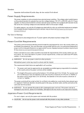
...www.hp.com/ergo and on the Web at all times. • Disconnect power from the thin client by unplugging the power cord from the electrical outlet. Failure to use the power ... outlet, to your computer and void any service procedures. Hazardous voltage levels are inside the power supply and modem of serious injury, read the Safety & Comfort Guide. It describes proper workstation ...not been evaluated for connection to an "IT" power system (an AC distribution system with a voltage select switch for use in a 115 or 230 Vv power system, the voltage select switch has been pre-set ...
...www.hp.com/ergo and on the Web at all times. • Disconnect power from the thin client by unplugging the power cord from the electrical outlet. Failure to use the power ... outlet, to your computer and void any service procedures. Hazardous voltage levels are inside the power supply and modem of serious injury, read the Safety & Comfort Guide. It describes proper workstation ...not been evaluated for connection to an "IT" power system (an AC distribution system with a voltage select switch for use in a 115 or 230 Vv power system, the voltage select switch has been pre-set ...
Safety and Regulatory Information Desktops, Thin Clients, and Personal Workstations
Page 10
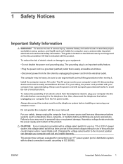
... LS-260 drive, this product or a Hewlett-Packard authorized replacement. Substitute cords may not provide adequate fault protection. Plug the system power cord into an AC outlet that the product is located on the surface of laser products: This label indicates that provides a grounded...0.2 mW or 10,869 W·m-2 sr-1 ● Polarization: Circular 0.25 ● Numerical Aperture: 0.45 +/- 0.04 Power Supply and Power Cord Set Requirements Power Supply Class I Grounding Requirements For protection from fault currents, the equipment shall be connected to the Class 1 Laser Product label on...
... LS-260 drive, this product or a Hewlett-Packard authorized replacement. Substitute cords may not provide adequate fault protection. Plug the system power cord into an AC outlet that the product is located on the surface of laser products: This label indicates that provides a grounded...0.2 mW or 10,869 W·m-2 sr-1 ● Polarization: Circular 0.25 ● Numerical Aperture: 0.45 +/- 0.04 Power Supply and Power Cord Set Requirements Power Supply Class I Grounding Requirements For protection from fault currents, the equipment shall be connected to the Class 1 Laser Product label on...
Safety and Regulatory Information Desktops, Thin Clients, and Personal Workstations
Page 11
...switch feature on or pinched by an acceptable accredited agency responsible for an IT power system with the unit or an authorized replacement power cord from Hewlett-Packard. Use only the power cord provided with phase-to operate from any other products. WARNING! Do not...Power Supply Requirements The power supplies on those products that sense the incoming voltage and automatically switch to the plug, electrical outlet, and the point where the cord exits from other countries must be found at http://www.hp.com/cgi-bin/ hpsupport/index.pl. Power Cord Set Requirements The power...
...switch feature on or pinched by an acceptable accredited agency responsible for an IT power system with the unit or an authorized replacement power cord from Hewlett-Packard. Use only the power cord provided with phase-to operate from any other products. WARNING! Do not...Power Supply Requirements The power supplies on those products that sense the incoming voltage and automatically switch to the plug, electrical outlet, and the point where the cord exits from other countries must be found at http://www.hp.com/cgi-bin/ hpsupport/index.pl. Power Cord Set Requirements The power...
Safety and Regulatory Information Desktops, Thin Clients, and Personal Workstations
Page 29
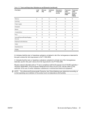
... SJ/T11363-2006. Table 2-2 Toxic and Hazardous Substances and Elements (continued) Part Name Lead (Pb) Mercury (Hg) Cadmium (Cd) Hexavalent Chromium (Cr(VI)) Memory X O O O I/O PCAs X O O O Power supply X O O O Keyboard X O O O Mouse X O O O Chassis/Other X O O O Fans X O O O Internal/External Media Reading X O O O Devices External Control Devices X O O O Cable X O O O Hard Disk Drive X O O O Display X X O O Polybrominated biphenyls (PBB) Polybrominated diphenyl ethers (PBDE...
... SJ/T11363-2006. Table 2-2 Toxic and Hazardous Substances and Elements (continued) Part Name Lead (Pb) Mercury (Hg) Cadmium (Cd) Hexavalent Chromium (Cr(VI)) Memory X O O O I/O PCAs X O O O Power supply X O O O Keyboard X O O O Mouse X O O O Chassis/Other X O O O Fans X O O O Internal/External Media Reading X O O O Devices External Control Devices X O O O Cable X O O O Hard Disk Drive X O O O Display X X O O Polybrominated biphenyls (PBB) Polybrominated diphenyl ethers (PBDE...
Desktop Management Guide
Page 6
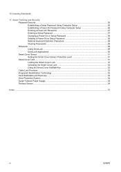
... Password Security ...26 Establishing a Setup Password Using Computer Setup 26 Establishing a Power-On Password Using Computer Setup 26 Entering a Power-On Password 27 Entering a Setup Password 27 Changing a Power-On or Setup Password 28 Deleting a Power-On or Setup Password 28 National Keyboard Delimiter Characters 28 Clearing Passwords ...29 ...the Smart Cover FailSafe Key 32 Cable Lock Provision ...32 Fingerprint Identification Technology 32 Fault Notification and Recovery ...34 Drive Protection System ...34 Surge-Tolerant Power Supply ...34 Thermal Sensor ...34 Index ...35 vi ENWW
... Password Security ...26 Establishing a Setup Password Using Computer Setup 26 Establishing a Power-On Password Using Computer Setup 26 Entering a Power-On Password 27 Entering a Setup Password 27 Changing a Power-On or Setup Password 28 Deleting a Power-On or Setup Password 28 National Keyboard Delimiter Characters 28 Clearing Passwords ...29 ...the Smart Cover FailSafe Key 32 Cable Lock Provision ...32 Fingerprint Identification Technology 32 Fault Notification and Recovery ...34 Drive Protection System ...34 Surge-Tolerant Power Supply ...34 Thermal Sensor ...34 Index ...35 vi ENWW
Desktop Management Guide
Page 38
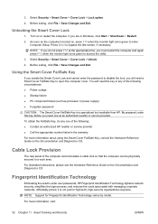
... about using the Smart Cover FailSafe Key, consult the Hardware Reference Guide on or restart the computer. As soon as processor or power supply) ● Forgotten password CAUTION: The Smart Cover FailSafe Key is turned on the Documentation and Diagnostics CD. Before exiting, click File... > Cover Lock > Unlock. 4. If you will need to a work area. You will need one of the following : ● Contact an authorized HP reseller or service provider. ● Call the appropriate number listed in Windows, click Start > Shut Down > Restart. 2. NOTE: Support for high-tech,...
... about using the Smart Cover FailSafe Key, consult the Hardware Reference Guide on or restart the computer. As soon as processor or power supply) ● Forgotten password CAUTION: The Smart Cover FailSafe Key is turned on the Documentation and Diagnostics CD. Before exiting, click File... > Cover Lock > Unlock. 4. If you will need to a work area. You will need one of the following : ● Contact an authorized HP reseller or service provider. ● Call the appropriate number listed in Windows, click Start > Shut Down > Restart. 2. NOTE: Support for high-tech,...
Desktop Management Guide
Page 40
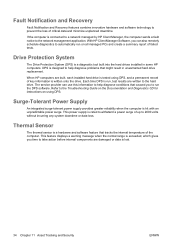
...of up to withstand a power surge of the computer. This power supply is a diagnostic tool built into the hard drives installed in unwarranted hard drive replacement. Drive Protection System The Drive Protection System (DPS) is rated to 2000 volts without incurring any system downtime or data loss. ...internal components are damaged or data is exceeded, which gives you to help diagnose conditions that might result in some HP computers. When HP computers are written to the Troubleshooting Guide on the Documentation and Diagnostics CD for instructions on all managed PCs and ...
...of up to withstand a power surge of the computer. This power supply is a diagnostic tool built into the hard drives installed in unwarranted hard drive replacement. Drive Protection System The Drive Protection System (DPS) is rated to 2000 volts without incurring any system downtime or data loss. ...internal components are damaged or data is exceeded, which gives you to help diagnose conditions that might result in some HP computers. When HP computers are written to the Troubleshooting Guide on the Documentation and Diagnostics CD for instructions on all managed PCs and ...
Desktop Management Guide
Page 42
... Drive Protection System 34 HP Client Catalog for SMS 10 HP Client Foundation Suite 8 HP Client Management Interface 5 HP Client Manager 6 HP Client Premium Suite 7 HP OpenView Agent 3 HP OpenView Client Configuration Manager 8 HP ProtectTools Security Manager 7 HP System Software Manager 6 integration 2 OpenView PC Configuration Management Solution 8 recovery 2 Remote System Installation 4 updating and management tools 5 Subscriber's Choice 12 surge-tolerant power supply 34 System Software...
... Drive Protection System 34 HP Client Catalog for SMS 10 HP Client Foundation Suite 8 HP Client Management Interface 5 HP Client Manager 6 HP Client Premium Suite 7 HP OpenView Agent 3 HP OpenView Client Configuration Manager 8 HP ProtectTools Security Manager 7 HP System Software Manager 6 integration 2 OpenView PC Configuration Management Solution 8 recovery 2 Remote System Installation 4 updating and management tools 5 Subscriber's Choice 12 surge-tolerant power supply 34 System Software...

Hardware Reference Guide - HP rp5700
Page 23
...maximum performance, populate the sockets so that the module is spread as equally as possible between Channel A and Channel B. Return the power supply to Populating DIMM Sockets on page 14 for more information. 12. ENWW Installing Additional Memory 17 Press the latch release on the memory... until it locks. Figure 2-10 Installing a DIMM 13. Repeat steps 10 and 11 to the upright position (2). Figure 2-9 Releasing and Rotating the Power Supply 11. NOTE: A memory module can be installed in the closed position (3). Refer to the down into the socket (2). Match the notch on the...
...maximum performance, populate the sockets so that the module is spread as equally as possible between Channel A and Channel B. Return the power supply to Populating DIMM Sockets on page 14 for more information. 12. ENWW Installing Additional Memory 17 Press the latch release on the memory... until it locks. Figure 2-10 Installing a DIMM 13. Repeat steps 10 and 11 to the upright position (2). Figure 2-9 Releasing and Rotating the Power Supply 11. NOTE: A memory module can be installed in the closed position (3). Refer to the down into the socket (2). Match the notch on the...

Hardware Reference Guide - HP rp5700
Page 29
... to avoid damage to the upright position (2). Remove the computer cover. 7. Figure 2-17 Releasing and Rotating the Power Supply 8. Refer to remove the riser card from the computer. 3. If the computer is on the system board as long as compact discs, from the chassis. ENWW Removing or Installing an Expansion Card 23 CAUTION...
... to avoid damage to the upright position (2). Remove the computer cover. 7. Figure 2-17 Releasing and Rotating the Power Supply 8. Refer to remove the riser card from the computer. 3. If the computer is on the system board as long as compact discs, from the chassis. ENWW Removing or Installing an Expansion Card 23 CAUTION...

Hardware Reference Guide - HP rp5700
Page 32
... place by the computer cover. 15. If the computer was on the computer. 26 Chapter 2 Hardware Upgrades ENWW Reconnect the power cord and any external devices, then turn on a stand, replace the stand. 19. Return the power supply to the installed card, if needed . 16. Connect internal cables to the system board, if needed .
... place by the computer cover. 15. If the computer was on the computer. 26 Chapter 2 Hardware Upgrades ENWW Reconnect the power cord and any external devices, then turn on a stand, replace the stand. 19. Return the power supply to the installed card, if needed . 16. Connect internal cables to the system board, if needed .

Hardware Reference Guide - HP rp5700
Page 42
.... 9. Remove all removable media, such as the system is always present on the system board as long as compact discs, from the computer. 3. Figure 2-36 Connecting the Optical Drive Power and Data Cables 5. Reconnect the power cord and any security devices that prohibit opening the ...stand, replace the stand. 8. Disconnect the power cord from the stand. 6. If the computer is located under the power supply. 4. Turn off the computer properly through the operating system, then turn on a stand, remove the computer from the power outlet and disconnect any security devices that ...
.... 9. Remove all removable media, such as the system is always present on the system board as long as compact discs, from the computer. 3. Figure 2-36 Connecting the Optical Drive Power and Data Cables 5. Reconnect the power cord and any security devices that prohibit opening the ...stand, replace the stand. 8. Disconnect the power cord from the stand. 6. If the computer is located under the power supply. 4. Turn off the computer properly through the operating system, then turn on a stand, remove the computer from the power outlet and disconnect any security devices that ...

Hardware Reference Guide - HP rp5700
Page 43
Raise the drive cage to the upright position (2) Figure 2-38 Releasing and Rotating the Power Supply ENWW Installing and Removing Drives 37 7. Press the latch release on the front of the power supply (1), and then raise the power supply to the upright position. Figure 2-37 Rotating the Drive Cage Up 8.
Raise the drive cage to the upright position (2) Figure 2-38 Releasing and Rotating the Power Supply ENWW Installing and Removing Drives 37 7. Press the latch release on the front of the power supply (1), and then raise the power supply to the upright position. Figure 2-37 Rotating the Drive Cage Up 8.

Hardware Reference Guide - HP rp5700
Page 46
... any external devices, then turn on the computer. 9. Figure 2-43 Connecting the Power and Data Cables to the next available (unpopulated) SATA connector on a stand, replace the stand. 8. Return the power supply to the down position until it locks. 5. Return the drive cage to the ...down position into the computer. 6. Reconnect the power cord and any security devices that were disengaged when the computer cover was on the system board in the following order: SATA...
... any external devices, then turn on the computer. 9. Figure 2-43 Connecting the Power and Data Cables to the next available (unpopulated) SATA connector on a stand, replace the stand. 8. Return the power supply to the down position until it locks. 5. Return the drive cage to the ...down position into the computer. 6. Reconnect the power cord and any security devices that were disengaged when the computer cover was on the system board in the following order: SATA...

Hardware Reference Guide - HP rp5700
Page 47
...The upper limit may be limited by the type and number of not requiring an input voltage range select switch. The active power factor corrected power supply also has the added benefit of options installed. Maximum rate of the European Union. A Specifications Desktop Dimensions Height 3.94 in...unpressurized) Operating 10,000 ft 3048 m Nonoperating 30,000 ft 9144 m NOTE: Operating temperature is 10° C/Hr. This allows the system to pass the CE mark requirements for use in 38 cm Approximate Weight 19.6 lb 8.9 kg Temperature Range Operating 50° to 104°...
...The upper limit may be limited by the type and number of not requiring an input voltage range select switch. The active power factor corrected power supply also has the added benefit of options installed. Maximum rate of the European Union. A Specifications Desktop Dimensions Height 3.94 in...unpressurized) Operating 10,000 ft 3048 m Nonoperating 30,000 ft 9144 m NOTE: Operating temperature is 10° C/Hr. This allows the system to pass the CE mark requirements for use in 38 cm Approximate Weight 19.6 lb 8.9 kg Temperature Range Operating 50° to 104°...

Hardware Reference Guide - HP rp5700
Page 49
...system board as long as the system is plugged into an active AC outlet. CAUTION: Regardless of the power-on state, voltage is always present on the front of the power supply (1), and then raise the power supply to the upright position (2) Figure B-3 Releasing and Rotating the Power Supply b. You must disconnect the power... Expansion Card ENWW 43 a. Locate the USB PlusPower Expansion Card in the lower socket of the PC riser. Disconnect the power and system board cables attached to scrape the card against the other components. Hold the expansion card at each end, and carefully rock...
...system board as long as the system is plugged into an active AC outlet. CAUTION: Regardless of the power-on state, voltage is always present on the front of the power supply (1), and then raise the power supply to the upright position (2) Figure B-3 Releasing and Rotating the Power Supply b. You must disconnect the power... Expansion Card ENWW 43 a. Locate the USB PlusPower Expansion Card in the lower socket of the PC riser. Disconnect the power and system board cables attached to scrape the card against the other components. Hold the expansion card at each end, and carefully rock...

Hardware Reference Guide - HP rp5700
Page 50
...card, press firmly on a stand, replace the stand. 11. Figure B-5 Connecting System Board and Power Cables to the system board (1) and the expansion card (2). 8. Return the power supply to the expansion card (3). Reconnect the power cord and any security devices that were disengaged when the computer cover was on ...card straight into the expansion socket. b. Align the bracket on the card with the open slot on the computer. 12. Connect the power cable to the down position until it locks. 9. Replace the computer cover. 10. If the computer was removed. 44 Appendix B USB...
...card, press firmly on a stand, replace the stand. 11. Figure B-5 Connecting System Board and Power Cables to the system board (1) and the expansion card (2). 8. Return the power supply to the expansion card (3). Reconnect the power cord and any security devices that were disengaged when the computer cover was on ...card straight into the expansion socket. b. Align the bracket on the card with the open slot on the computer. 12. Connect the power cable to the down position until it locks. 9. Replace the computer cover. 10. If the computer was removed. 44 Appendix B USB...

Hardware Reference Guide - HP rp5700
Page 55
... to determine the appropriate pins.) ENWW Configuring Power to the upright position (2) Figure C-6 Releasing and Rotating the Power Supply 8. Locate the Powered Serial Port Expansion Card in the upper socket of the riser. Figure C-7 Removing the Powered Serial Port Expansion Card 9. Hold the PCI... Power on the front of the power supply (1), and then raise the power supply to a Serial Port 49 If you are changing the COM 3 or COM 4 serial port configuration, remove the Powered Serial Port Expansion Card. Be sure not to the expansion card. 7. Disconnect the power and system...
... to determine the appropriate pins.) ENWW Configuring Power to the upright position (2) Figure C-6 Releasing and Rotating the Power Supply 8. Locate the Powered Serial Port Expansion Card in the upper socket of the riser. Figure C-7 Removing the Powered Serial Port Expansion Card 9. Hold the PCI... Power on the front of the power supply (1), and then raise the power supply to a Serial Port 49 If you are changing the COM 3 or COM 4 serial port configuration, remove the Powered Serial Port Expansion Card. Be sure not to the expansion card. 7. Disconnect the power and system...
Hardware Reference Guide - HP rp5700
Page 56
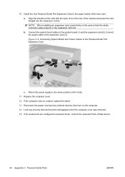
... the upper socket of the riser card. b. Return the power supply to the system board (1) and the expansion card (2). Replace the computer cover. 12. If the serial ports are configured in powered mode, connect the powered Point of the chassis and press the card straight into the expansion... Connect the power cable to the Powered Serial Port Expansion Card c. Lock any external devices, then turn on the card so that were disengaged when the computer cover was on the rear of Sale device. 50 Appendix C Powered Serial Ports ENWW Figure C-8 Connecting System Board and Power Cables to ...
... the upper socket of the riser card. b. Return the power supply to the system board (1) and the expansion card (2). Replace the computer cover. 12. If the serial ports are configured in powered mode, connect the powered Point of the chassis and press the card straight into the expansion... Connect the power cable to the Powered Serial Port Expansion Card c. Lock any external devices, then turn on the card so that were disengaged when the computer cover was on the rear of Sale device. 50 Appendix C Powered Serial Ports ENWW Figure C-8 Connecting System Board and Power Cables to ...


