Maintenance and Service Guide
Page 3
... the Audio PCA ...2-38 Removing the Heat Sink (with Fan 2-40 Removing the CPU Module ...2-44 Removing the RJ11/1394 Connector Module 2-48 Removing the Motherboard ...2-50 Replacing Components on a Bottom Case 2-59 Repairing the BIOS IC...2-61 Removing Other Components...2-63 Troubleshooting and Diagnostics 3-1 Support Service Partners...3-2 Troubleshooting ...3-3 Diagnostic Tools...
... the Audio PCA ...2-38 Removing the Heat Sink (with Fan 2-40 Removing the CPU Module ...2-44 Removing the RJ11/1394 Connector Module 2-48 Removing the Motherboard ...2-50 Replacing Components on a Bottom Case 2-59 Repairing the BIOS IC...2-61 Removing Other Components...2-63 Troubleshooting and Diagnostics 3-1 Support Service Partners...3-2 Troubleshooting ...3-3 Diagnostic Tools...
Maintenance and Service Guide
Page 4
... 2-39 Figure 2-33. Bottom View...1-10 Figure 1-4. Removing the Battery ...2-4 Figure 2-3. Removing the Top Case Screws 2-29 Figure 2-20. Removing the Motherboard 2-51 Figure 2-35. Back View ...1-12 Figure 1-6. Resetting the Notebook ...1-17 Figure 1-8. Removing an SDRAM Module 2-5 Figure 2-4. Removing the Mini PCI Card 2-8 Figure 2-7. Removing the Keyboard ...2-17 Figure 2-13. Removing...
... 2-39 Figure 2-33. Bottom View...1-10 Figure 1-4. Removing the Battery ...2-4 Figure 2-3. Removing the Top Case Screws 2-29 Figure 2-20. Removing the Motherboard 2-51 Figure 2-35. Back View ...1-12 Figure 1-6. Resetting the Notebook ...1-17 Figure 1-8. Removing an SDRAM Module 2-5 Figure 2-4. Removing the Mini PCI Card 2-8 Figure 2-7. Removing the Keyboard ...2-17 Figure 2-13. Removing...
Maintenance and Service Guide
Page 5
...Beep Codes 3-20 Table 3-5. POST Messages ...3-24 Table 3-6. Exploded View ...4-2 Figure 4-2. Main Status Lights (front of notebook 1-15 Table 1-4. Removing Components...2-63 Table 3-1. Sycard PCCtest Commands ...3-26 Table 3-7. Basic Troubleshooting Steps ...3-3 Figure 4-1. Removing.... Recommended Screw Torque Values 2-2 Table 2-4. LCD Guidelines ...5-4 Service Manual v Figure 2-36. Removing the Motherboard 2-56 Figure 2-38. Keyboard Status Lights...1-15 Table 1-5. Accessories ...1-22 Table 1-8. Removal Cross-Reference ...2-1 Table 2-2. Activating Power...
...Beep Codes 3-20 Table 3-5. POST Messages ...3-24 Table 3-6. Exploded View ...4-2 Figure 4-2. Main Status Lights (front of notebook 1-15 Table 1-4. Removing Components...2-63 Table 3-1. Sycard PCCtest Commands ...3-26 Table 3-7. Basic Troubleshooting Steps ...3-3 Figure 4-1. Removing.... Recommended Screw Torque Values 2-2 Table 2-4. LCD Guidelines ...5-4 Service Manual v Figure 2-36. Removing the Motherboard 2-56 Figure 2-38. Keyboard Status Lights...1-15 Table 1-5. Accessories ...1-22 Table 1-8. Removal Cross-Reference ...2-1 Table 2-2. Activating Power...
Maintenance and Service Guide
Page 29
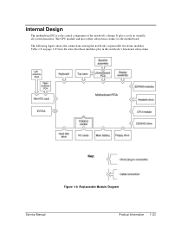
The following figure shows the connections among the notebook's replaceable electronic modules. Internal Design The motherboard PCA is the central component of the notebook's design. Table 1-8 on page 1-25 lists the roles that these modules play in virtually all system functions. Replaceable Module Diagram Service Manual Product Information 1-23 The CPU module and most other subsystems connect to the motherboard. It plays a role in the notebook's functional subsystems. Figure 1-8.
The following figure shows the connections among the notebook's replaceable electronic modules. Internal Design The motherboard PCA is the central component of the notebook's design. Table 1-8 on page 1-25 lists the roles that these modules play in virtually all system functions. Replaceable Module Diagram Service Manual Product Information 1-23 The CPU module and most other subsystems connect to the motherboard. It plays a role in the notebook's functional subsystems. Figure 1-8.
Maintenance and Service Guide
Page 30
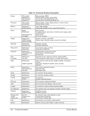
... disk drive Floppy drive CPU module Motherboard Motherboard SDRAM module Battery Motherboard Switchboard PCA AC adapter Motherboard SDRAM module Display assembly Motherboard Hard disk drive Motherboard Floppy drive Motherboard Switchboard PCA Keyboard Motherboard Top case Motherboard Speaker assembly Motherboard Switchboard PCA Top case Motherboard Motherboard Motherboard IR PCA Motherboard Motherboard Motherboard Motherboard Motherboard PCMCIA socket Mini PCI Antenna PCAs IR PCA Motherboard Motherboard Main processor (MMO) Primary system circuitry, system...
... disk drive Floppy drive CPU module Motherboard Motherboard SDRAM module Battery Motherboard Switchboard PCA AC adapter Motherboard SDRAM module Display assembly Motherboard Hard disk drive Motherboard Floppy drive Motherboard Switchboard PCA Keyboard Motherboard Top case Motherboard Speaker assembly Motherboard Switchboard PCA Top case Motherboard Motherboard Motherboard IR PCA Motherboard Motherboard Motherboard Motherboard Motherboard PCMCIA socket Mini PCI Antenna PCAs IR PCA Motherboard Motherboard Main processor (MMO) Primary system circuitry, system...
Maintenance and Service Guide
Page 31
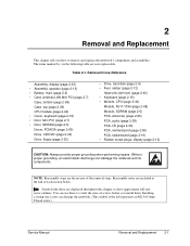
... RJ11/1394 (page 2-48) Module, SDRAM (page 2-5) PCA, antennas (page 2-60) PCA, audio (page 2-38) PCA, I/R (page 2-36) PCA, motherboard (page 2-50) PCA, switchboard (page 2-19) • Rubber screw plugs, display (page 2-12) CAUTION: Always provide proper grounding when performing repairs. Reassembly notes...head screw). The items marked by • in the following table are displayed throughout this chapter to remove and replace the notebook's components and assemblies. 2 Removal and Replacement This chapter tells you install them. Service Manual Removal and Replacement 2-1 You ...
... RJ11/1394 (page 2-48) Module, SDRAM (page 2-5) PCA, antennas (page 2-60) PCA, audio (page 2-38) PCA, I/R (page 2-36) PCA, motherboard (page 2-50) PCA, switchboard (page 2-19) • Rubber screw plugs, display (page 2-12) CAUTION: Always provide proper grounding when performing repairs. Reassembly notes...head screw). The items marked by • in the following table are displayed throughout this chapter to remove and replace the notebook's components and assemblies. 2 Removal and Replacement This chapter tells you install them. Service Manual Removal and Replacement 2-1 You ...
Maintenance and Service Guide
Page 35
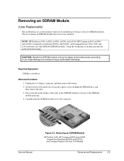
...Procedure 1. Removing an SDRAM Module HP Pavilion 4x00, HP Compaq nx9005 and nx9000, Compaq Evo Notebook N1050v and N1010v, and Compaq Presario 2100 and 1100 Models Removal and Replacement 2-5 Press outward on the latches at the sides of the notebook, loosen the captive screws holding ...module only by its motherboard, but has 2 slots for SDRAM modules. Service Manual Figure 2-3. Unplug the AC adapter, if present, and then remove the battery. 2. NOTE: HP Pavilion ze5300, ze5200, ze4300, ze4200, and ze4100, HP Compaq nx9010, nx9005 and nx9000, Compaq Evo Notebook N1050v and N1010v,...
...Procedure 1. Removing an SDRAM Module HP Pavilion 4x00, HP Compaq nx9005 and nx9000, Compaq Evo Notebook N1050v and N1010v, and Compaq Presario 2100 and 1100 Models Removal and Replacement 2-5 Press outward on the latches at the sides of the notebook, loosen the captive screws holding ...module only by its motherboard, but has 2 slots for SDRAM modules. Service Manual Figure 2-3. Unplug the AC adapter, if present, and then remove the battery. 2. NOTE: HP Pavilion ze5300, ze5200, ze4300, ze4200, and ze4100, HP Compaq nx9010, nx9005 and nx9000, Compaq Evo Notebook N1050v and N1010v,...
Maintenance and Service Guide
Page 46
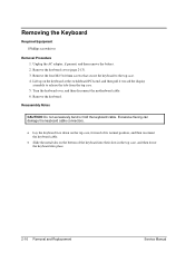
... four M2.5×4.0mm screws that secure the keyboard to release the tabs from the top case. 5. Turn the keyboard over, and then disconnect the motherboard cable. 6. Reassembly Notes CAUTION: Do not excessively bend or fold the keyboard cable. Lift up on the bottom of the keyboard into their slots in...
... four M2.5×4.0mm screws that secure the keyboard to release the tabs from the top case. 5. Turn the keyboard over, and then disconnect the motherboard cable. 6. Reassembly Notes CAUTION: Do not excessively bend or fold the keyboard cable. Lift up on the bottom of the keyboard into their slots in...
Maintenance and Service Guide
Page 48
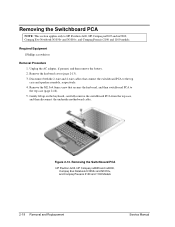
...motherboard cable. Figure 2-13. Disconnect both the 2-wire and 4-wire cables that secures the keyboard, and then switchboard PCA to the top case (page 2-16). 5. Remove the M2.5×4.0mm screw that connect the switchboard PCA to HP Pavilion 4x00, HP Compaq nx9005 and nx9000, Compaq Evo Notebook...assembly, respectively. 4. Required Equipment 1 Phillips screwdriver Removal Procedure 1. Removing the Switchboard PCA HP Pavilion 4x00, HP Compaq nx9005 and nx9000, Compaq Evo Notebook N1050v and N1010v, and Compaq Presario 2100 and 1100 Models 2-18 Removal and Replacement Service Manual
...motherboard cable. Figure 2-13. Disconnect both the 2-wire and 4-wire cables that secures the keyboard, and then switchboard PCA to the top case (page 2-16). 5. Remove the M2.5×4.0mm screw that connect the switchboard PCA to HP Pavilion 4x00, HP Compaq nx9005 and nx9000, Compaq Evo Notebook...assembly, respectively. 4. Required Equipment 1 Phillips screwdriver Removal Procedure 1. Removing the Switchboard PCA HP Pavilion 4x00, HP Compaq nx9005 and nx9000, Compaq Evo Notebook N1050v and N1010v, and Compaq Presario 2100 and 1100 Models 2-18 Removal and Replacement Service Manual
Maintenance and Service Guide
Page 49
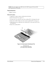
...to the display lid switch. 4. Removing the Switchboard PCA HP Pavilion 5x00, HP Compaw nx9010 and nx9008, and Compaq Presario 2500 Models Service Manual Removal and Replacement 2-19 NOTE: This section applies only to disconnect the PCA from the motherboard. 6. Remove the two M2.5×4.0mm screws that ...switchboard PCA. Remove the keyboard cover (page 2-13). 3. Gently lift up on the rear right edge of the switchboard PCA to HP Pavilion 5x00, HP Compaq nx9010 and nx9008, and Compaq Presario 2500 models. Required Equipment 1 Phillips screwdriver Removal Procedure 1.
...to the display lid switch. 4. Removing the Switchboard PCA HP Pavilion 5x00, HP Compaw nx9010 and nx9008, and Compaq Presario 2500 Models Service Manual Removal and Replacement 2-19 NOTE: This section applies only to disconnect the PCA from the motherboard. 6. Remove the two M2.5×4.0mm screws that ...switchboard PCA. Remove the keyboard cover (page 2-13). 3. Gently lift up on the rear right edge of the switchboard PCA to HP Pavilion 5x00, HP Compaq nx9010 and nx9008, and Compaq Presario 2500 models. Required Equipment 1 Phillips screwdriver Removal Procedure 1.
Maintenance and Service Guide
Page 50
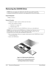
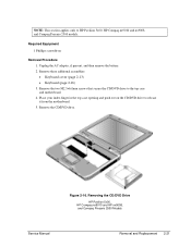
...CD/DVD drive are installed in the top case opening, and then push out on the CD/DVD drive to HP Pavilion 4x00, HP Compaq nx9005 and nx9000, Compaq Evo Notebook N1050v and N1010v, and Compaq Presario 2100 and 1100 models. Remove the CD/DVD drive. Removing the CD/DVD... Evo Notebook N1050v and N1010v, and Compaq Presario 2100 and 1100 Models 2-20 Removal and Replacement Service Manual Make sure these additional assemblies: • Keyboard cover (page 2-13) • Keyboard (page 2-16) 3. Removing the CD/DVD Drive NOTE: This section applies only to release it from the motherboard. 5....
...CD/DVD drive are installed in the top case opening, and then push out on the CD/DVD drive to HP Pavilion 4x00, HP Compaq nx9005 and nx9000, Compaq Evo Notebook N1050v and N1010v, and Compaq Presario 2100 and 1100 models. Remove the CD/DVD drive. Removing the CD/DVD... Evo Notebook N1050v and N1010v, and Compaq Presario 2100 and 1100 Models 2-20 Removal and Replacement Service Manual Make sure these additional assemblies: • Keyboard cover (page 2-13) • Keyboard (page 2-16) 3. Removing the CD/DVD Drive NOTE: This section applies only to release it from the motherboard. 5....
Maintenance and Service Guide
Page 51
...the two M2.5×6.0mm screws that secure the CD/DVD drive to HP Pavilion 5x00, HP Compaq nx9010 and nx9008, and Compaq Presario 2500 models. Figure 2-16. NOTE: This section applies only to the top case and motherboard. 4. Required Equipment 1 Phillips screwdriver Removal Procedure 1. Remove these additional ...in the top case opening and push out on the CD/DVD drive to release it from the motherboard. 5. Removing the CD/DVD Drive HP Pavilion 5x00, HP Compaq nx9010 and HP nx9008, and Compaq Presario 2500 Models Service Manual Removal and Replacement 2-21 Unplug the AC adapter,...
...the two M2.5×6.0mm screws that secure the CD/DVD drive to HP Pavilion 5x00, HP Compaq nx9010 and nx9008, and Compaq Presario 2500 models. Figure 2-16. NOTE: This section applies only to the top case and motherboard. 4. Required Equipment 1 Phillips screwdriver Removal Procedure 1. Remove these additional ...in the top case opening and push out on the CD/DVD drive to release it from the motherboard. 5. Removing the CD/DVD Drive HP Pavilion 5x00, HP Compaq nx9010 and HP nx9008, and Compaq Presario 2500 Models Service Manual Removal and Replacement 2-21 Unplug the AC adapter,...
Maintenance and Service Guide
Page 52
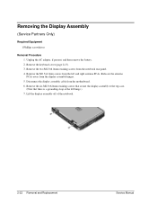
...two M2.5×6.0mm retaining screws from the display assembly hinges. 5. Lift the display assembly off of the notebook. 2-22 Removal and Replacement Service Manual Removing the Display Assembly (Service Partners Only) Required Equipment 1 Phillips ...screwdriver Removal Procedure 1. Relocate the antenna PCAs away from the notebook rear panel. 4. Remove the keyboard cover (page 2-13). 3. Disconnect the display assembly cable from the left ...PCAs. Remove the M2.5×4.0mm screws from the motherboard. 6.
...two M2.5×6.0mm retaining screws from the display assembly hinges. 5. Lift the display assembly off of the notebook. 2-22 Removal and Replacement Service Manual Removing the Display Assembly (Service Partners Only) Required Equipment 1 Phillips ...screwdriver Removal Procedure 1. Relocate the antenna PCAs away from the notebook rear panel. 4. Remove the keyboard cover (page 2-13). 3. Disconnect the display assembly cable from the left ...PCAs. Remove the M2.5×4.0mm screws from the motherboard. 6.
Maintenance and Service Guide
Page 53
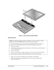
. Download the notebook series service package from the Partnership Web site (see the HP logo, press esc to display the boot menu, then boot from the floppy drive. 6. If the unit has no internal floppy drive, connect a USB floppy drive. 4. Turn on the motherboard for the new ... with the display assembly hinges. Removing the Display Assembly NOTE: After replacing the display assembly or motherboard, you connect the grounding strap to reprogram the EEPROM on the notebook. 5. Service Manual Removal and Replacement 2-23 Reassembly Notes Figure 2-17. Insert the Service Utilities ...
. Download the notebook series service package from the Partnership Web site (see the HP logo, press esc to display the boot menu, then boot from the floppy drive. 6. If the unit has no internal floppy drive, connect a USB floppy drive. 4. Turn on the motherboard for the new ... with the display assembly hinges. Removing the Display Assembly NOTE: After replacing the display assembly or motherboard, you connect the grounding strap to reprogram the EEPROM on the notebook. 5. Service Manual Removal and Replacement 2-23 Reassembly Notes Figure 2-17. Insert the Service Utilities ...
Maintenance and Service Guide
Page 54
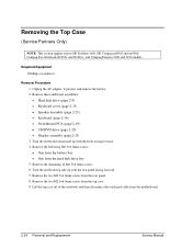
...motherboard. 2-24 Removal and Replacement Service Manual Lift the top case off of the notebook and then disconnect the touch pad cable from the top case. 9. Remove the two M2.5×4.0mm screws from the hard disk drive bay 5. Removing the Top Case (Service Partners Only) NOTE: This section applies only to HP Pavilion... 4x00, HP Compaq nx9005 and nx9000, Compaq Evo Notebook N1050v and N1010v, and Compaq Presario 2100 and 1100 models. Unplug the AC adapter, if present, and...
...motherboard. 2-24 Removal and Replacement Service Manual Lift the top case off of the notebook and then disconnect the touch pad cable from the top case. 9. Remove the two M2.5×4.0mm screws from the hard disk drive bay 5. Removing the Top Case (Service Partners Only) NOTE: This section applies only to HP Pavilion... 4x00, HP Compaq nx9005 and nx9000, Compaq Evo Notebook N1050v and N1010v, and Compaq Presario 2100 and 1100 models. Unplug the AC adapter, if present, and...
Maintenance and Service Guide
Page 59
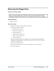
...page 2-16) • Switchboard PCA (page 2-19) • Display assembly (page 2-23) • Top case (page 2-26) 3. Disconnect the motherboard cable. 5. Unplug the AC adapter, if present, and remove the battery. 2. Remove the two M2.5×4.0mm screws that secure the floppy drive to the... motherboard. (Note that secure the hard disk drive guide to the motherboard. 6. Remove the floppy drive. Removing the Floppy Drive (Service Partners Only) NOTE: This section applies only to HP Pavilion ze4x00, HP Compaq nx9005 and nx9000, Compaq Evo Notebook N1050v and N1010v,...
...page 2-16) • Switchboard PCA (page 2-19) • Display assembly (page 2-23) • Top case (page 2-26) 3. Disconnect the motherboard cable. 5. Unplug the AC adapter, if present, and remove the battery. 2. Remove the two M2.5×4.0mm screws that secure the floppy drive to the... motherboard. (Note that secure the hard disk drive guide to the motherboard. 6. Remove the floppy drive. Removing the Floppy Drive (Service Partners Only) NOTE: This section applies only to HP Pavilion ze4x00, HP Compaq nx9005 and nx9000, Compaq Evo Notebook N1050v and N1010v,...
Maintenance and Service Guide
Page 60
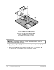
... Floppy Drive HP Pavilion 4x00, HP Compaq nx9005 and nx9000, Compaq Evo Notebook N1050v and N1010v, and Compaq Presario 2100 and 1100 Models Reassembly Notes CAUTION: Do not excessively bend or fold the floppy drive cable. Excessive flexing can damage the floppy drive cable connections. • Connect the floppy drive cable to the motherboard prior...
... Floppy Drive HP Pavilion 4x00, HP Compaq nx9005 and nx9000, Compaq Evo Notebook N1050v and N1010v, and Compaq Presario 2100 and 1100 Models Reassembly Notes CAUTION: Do not excessively bend or fold the floppy drive cable. Excessive flexing can damage the floppy drive cable connections. • Connect the floppy drive cable to the motherboard prior...
Maintenance and Service Guide
Page 64
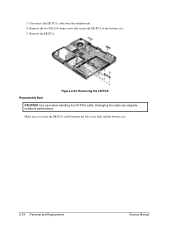
Reassembly Note Figure 2-24. Disconnect the I /R PCA cable. Removing the I/R PCA CAUTION: Use care when handling the I /R PCA cable from the motherboard. 4. 3. Remove the two M2.5×4.0mm screws that secure the I /R PCA cable between the left screw hole and the bottom case. 2-34 Removal and Replacement Service Manual Make sure you route the I /R PCA to the bottom case. 5. Remove the I/R PCA. Damaging the cable can degrade notebook performance.
Reassembly Note Figure 2-24. Disconnect the I /R PCA cable. Removing the I/R PCA CAUTION: Use care when handling the I /R PCA cable from the motherboard. 4. 3. Remove the two M2.5×4.0mm screws that secure the I /R PCA cable between the left screw hole and the bottom case. 2-34 Removal and Replacement Service Manual Make sure you route the I /R PCA to the bottom case. 5. Remove the I/R PCA. Damaging the cable can degrade notebook performance.
Maintenance and Service Guide
Page 65
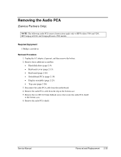
... PCA removal instructions apply only to the bottom case. 6. Remove the audio PCA cable from the motherboard. 4. Remove the two M2.0×3.0mm flathead screws that secure the audio PCA shield to HP Pavilion 5300 and 5200, HP Compaq nx9010, and Compaq Presario 2500 models. Remove the audio PCA shield. Required Equipment 1 Phillips screwdriver...
... PCA removal instructions apply only to the bottom case. 6. Remove the audio PCA cable from the motherboard. 4. Remove the two M2.0×3.0mm flathead screws that secure the audio PCA shield to HP Pavilion 5300 and 5200, HP Compaq nx9010, and Compaq Presario 2500 models. Remove the audio PCA shield. Required Equipment 1 Phillips screwdriver...
Maintenance and Service Guide
Page 68
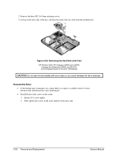
Removing the Heat Sink (with Fan) HP Pavilion 4x00, HP Compaq nx9005 and nx9000, Compaq Evo Notebook N1050v and N1010v, and Compaq Presario 2100 and 1100 Models CAUTION: Do not spin the fan blades with fan), and then disconnect the fan cable ... Removal and Replacement Service Manual Reassembly Notes • If the thermal pad is damaged, use a sharp knife or scraper to carefully remove it from the motherboard.
Removing the Heat Sink (with Fan) HP Pavilion 4x00, HP Compaq nx9005 and nx9000, Compaq Evo Notebook N1050v and N1010v, and Compaq Presario 2100 and 1100 Models CAUTION: Do not spin the fan blades with fan), and then disconnect the fan cable ... Removal and Replacement Service Manual Reassembly Notes • If the thermal pad is damaged, use a sharp knife or scraper to carefully remove it from the motherboard.


