
Maintenance and Service Guide
Page 6
Packaging and transporting guidelines 44 Component replacement procedures 46 Service tag ...46 Battery ...48 Hard drive ...49 RTC battery ...52 Optical drive ...53 Memory module ...56 Keyboard ...57 WLAN module ...62 Solid-state drive ...65 Top cover ...66 Power button board 70 Fingerprint reader ...
Packaging and transporting guidelines 44 Component replacement procedures 46 Service tag ...46 Battery ...48 Hard drive ...49 RTC battery ...52 Optical drive ...53 Memory module ...56 Keyboard ...57 WLAN module ...62 Solid-state drive ...65 Top cover ...66 Power button board 70 Fingerprint reader ...
Maintenance and Service Guide
Page 16
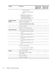
... (PFC, RC, V, √ EM, 3-wire) ● 65-W HP Smart AC adapter (RC, V, EM, √ 3-wire) ● 65-W HP Smart AC adapter (RC, V, 3- √ wire) Supports the following batteries: √ √ ● 9-cell, 100-Wh, 3.00-Ah, Li-ion battery ● 6-cell, 62-Wh, 2.80-Ah, Li-ion battery Supports security cable lock √ √ Supports...
... (PFC, RC, V, √ EM, 3-wire) ● 65-W HP Smart AC adapter (RC, V, EM, √ 3-wire) ● 65-W HP Smart AC adapter (RC, V, 3- √ wire) Supports the following batteries: √ √ ● 9-cell, 100-Wh, 3.00-Ah, Li-ion battery ● 6-cell, 62-Wh, 2.80-Ah, Li-ion battery Supports security cable lock √ √ Supports...
Maintenance and Service Guide
Page 17
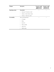
Category Operating system Serviceability Description Preinstalled: ● Windows® 7 Home Basic, 64-bit ● Windows 7 Home Premium, 64-bit ● Windows 7 Professional, 64-bit End user replaceable parts: ● AC adapter ● Battery ● Hard drive ● Memory module ● Optical drive ● WLAN module Computer model equipped with AMD processor Computer model equipped with Intel processor √ √ √ √ 9
Category Operating system Serviceability Description Preinstalled: ● Windows® 7 Home Basic, 64-bit ● Windows 7 Home Premium, 64-bit ● Windows 7 Professional, 64-bit End user replaceable parts: ● AC adapter ● Battery ● Hard drive ● Memory module ● Optical drive ● WLAN module Computer model equipped with AMD processor Computer model equipped with Intel processor √ √ √ √ 9

Maintenance and Service Guide
Page 27
... security cable to act as a deterrent, but it may not prevent the computer from the battery bay and opens the service cover. NOTE: The security cable is using DC power. Releases the battery from being mishandled or stolen. Bottom 19 Connects an AC adapter. Holds the... battery. Item (8) Component AC adapter light (9) (10) Power connector Security cable slot Bottom Description ● White: The...
... security cable to act as a deterrent, but it may not prevent the computer from the battery bay and opens the service cover. NOTE: The security cable is using DC power. Releases the battery from being mishandled or stolen. Bottom 19 Connects an AC adapter. Holds the... battery. Item (8) Component AC adapter light (9) (10) Power connector Security cable slot Bottom Description ● White: The...
Maintenance and Service Guide
Page 30
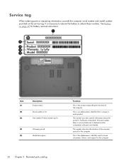
... ordering parts or requesting information, provide the computer serial number and model number provided on page 48 for battery removal instructions. See Battery on the service tag. This number describes the duration of the computer. This number provides specific information about...of the warranty period for the computer. 22 Chapter 3 Illustrated parts catalog This is an alphanumeric identifier that is necessary to remove the battery to obtain these numbers. Item (1) (2) (3) Description Product name Serial number (s/n) Part number/Product number (p/n) (4) Warranty period (5) ...
... ordering parts or requesting information, provide the computer serial number and model number provided on page 48 for battery removal instructions. See Battery on the service tag. This number describes the duration of the computer. This number provides specific information about...of the warranty period for the computer. 22 Chapter 3 Illustrated parts catalog This is an alphanumeric identifier that is necessary to remove the battery to obtain these numbers. Item (1) (2) (3) Description Product name Serial number (s/n) Part number/Product number (p/n) (4) Warranty period (5) ...

Maintenance and Service Guide
Page 36
...) 686926-001 Power connector cable (includes bracket) 686900-001 Base enclosure (includes battery release latch assembly) 686896-001 Battery: 9-cell, 100-Wh, 3.0-Ah, Li-ion battery 672412-001 6-cell, 62-Wh, 2.8-Ah, Li-ion battery 671731-001 DVD±RW Double-Layer with SuperMulti Drive (includes optical drive bezel... and optical drive bracket) 686916-001 RTC battery (includes cable and double-sided tape) 672349-001 Hard drive (does not include hard drive bracket, hard drive connector cable, or ...
...) 686926-001 Power connector cable (includes bracket) 686900-001 Base enclosure (includes battery release latch assembly) 686896-001 Battery: 9-cell, 100-Wh, 3.0-Ah, Li-ion battery 672412-001 6-cell, 62-Wh, 2.8-Ah, Li-ion battery 671731-001 DVD±RW Double-Layer with SuperMulti Drive (includes optical drive bezel... and optical drive bracket) 686916-001 RTC battery (includes cable and double-sided tape) 672349-001 Hard drive (does not include hard drive bracket, hard drive connector cable, or ...

Maintenance and Service Guide
Page 42
... module for use on all computer models 671731-001 6-cell, 62-Wh, 2.80-Ah, Li-ion battery 672349-001 RTC battery (includes cable and double-sided tape) 672412-001 9-cell, 100-Wh, 3.00-Ah, Li-ion battery 675794-001 Atheros WB225 1×1 802.11b/g/n Bluetooth Combo Adapter for use on all computer models...
... module for use on all computer models 671731-001 6-cell, 62-Wh, 2.80-Ah, Li-ion battery 672349-001 RTC battery (includes cable and double-sided tape) 672412-001 9-cell, 100-Wh, 3.00-Ah, Li-ion battery 675794-001 Atheros WB225 1×1 802.11b/g/n Bluetooth Combo Adapter for use on all computer models...

Maintenance and Service Guide
Page 43
... cable, or screws) NOTE: The hard drive bracket, hard drive connector cable, and screws are included in midnight black finish 686896-001 Base enclosure (includes battery release latch assembly) 686897-001 Display bezel 686898-001 Display panel cable (includes webcam/microphone module cable) 686899-001 Optical drive connector board (includes cable...
... cable, or screws) NOTE: The hard drive bracket, hard drive connector cable, and screws are included in midnight black finish 686896-001 Base enclosure (includes battery release latch assembly) 686897-001 Display bezel 686898-001 Display panel cable (includes webcam/microphone module cable) 686899-001 Optical drive connector board (includes cable...

Maintenance and Service Guide
Page 54
...computer. Service tag When ordering parts or requesting information, provide the computer serial number and model number provided on page 48 for battery removal instructions. The part number helps a service technician determine what components and parts are as many as 77 screws that is ...unique to obtain these numbers. There are needed. 46 Chapter 4 Removal and replacement procedures See Battery on the service tag. Make special note of the computer. This number provides specific information about the product's hardware components. Component ...
...computer. Service tag When ordering parts or requesting information, provide the computer serial number and model number provided on page 48 for battery removal instructions. The part number helps a service technician determine what components and parts are as many as 77 screws that is ...unique to obtain these numbers. There are needed. 46 Chapter 4 Removal and replacement procedures See Battery on the service tag. Make special note of the computer. This number provides specific information about the product's hardware components. Component ...

Maintenance and Service Guide
Page 56
... system. 2. Pivot the front edge of the battery bay. 2. Pivot the front edge of the battery down on a flat surface. 2. Disconnect all external devices from the computer. To insert the battery: 1. Slide the battery release latch (1) to release the battery. 3. Align the tabs on the rear edge ... steps: 1. Turn off or in Hibernation, turn the computer on the rear edge of the battery (2) up and back. 4. If you are unsure whether the computer is seated. (The battery release latch will automatically lock into place.) 48 Chapter 4 Removal and replacement procedures Remove the...
... system. 2. Pivot the front edge of the battery bay. 2. Pivot the front edge of the battery down on a flat surface. 2. Disconnect all external devices from the computer. To insert the battery: 1. Slide the battery release latch (1) to release the battery. 3. Align the tabs on the rear edge ... steps: 1. Turn off or in Hibernation, turn the computer on the rear edge of the battery (2) up and back. 4. If you are unsure whether the computer is seated. (The battery release latch will automatically lock into place.) 48 Chapter 4 Removal and replacement procedures Remove the...

Maintenance and Service Guide
Page 57
...: 1. Loosen the captive screw (1) that secures the service cover to release the service cover. (The service cover releases (3) forward.) Component replacement procedures 49 Slide the battery release latch (2) to the computer. 2. Description 1-TB, 5400-rpm, 9.5-mm 750-GB, 7200-rpm, 9.5-mm 750-GB, 5400-rpm, 9.5-mm 640-GB, ...-001 634925-001 669299-001 641672-001 622643-001 686907-001 Before removing the hard drive, follow these steps: 1. Remove the battery (see Battery on , and then shut it down through the operating system. 2. Turn off or in Hibernation, turn the computer on page 48).
...: 1. Loosen the captive screw (1) that secures the service cover to release the service cover. (The service cover releases (3) forward.) Component replacement procedures 49 Slide the battery release latch (2) to the computer. 2. Description 1-TB, 5400-rpm, 9.5-mm 750-GB, 7200-rpm, 9.5-mm 750-GB, 5400-rpm, 9.5-mm 640-GB, ...-001 634925-001 669299-001 641672-001 622643-001 686907-001 Before removing the hard drive, follow these steps: 1. Remove the battery (see Battery on , and then shut it down through the operating system. 2. Turn off or in Hibernation, turn the computer on page 48).

Maintenance and Service Guide
Page 60
... system. 2. Remove the RTC battery: 1. Reverse this procedure to the base enclosure with double-sided tape.) 3. Disconnect the RTC battery cable (1) from the base enclosure. (The RTC battery is off the computer. RTC battery Description RTC battery (includes cable and double-sided tape...) Spare part number 672349-001 Before removing the RTC battery, follow these steps: 1. Turn ...
... system. 2. Remove the RTC battery: 1. Reverse this procedure to the base enclosure with double-sided tape.) 3. Disconnect the RTC battery cable (1) from the base enclosure. (The RTC battery is off the computer. RTC battery Description RTC battery (includes cable and double-sided tape...) Spare part number 672349-001 Before removing the RTC battery, follow these steps: 1. Turn ...

Maintenance and Service Guide
Page 61
...external devices from the computer. 3. Remove the optical drive: 1. Turn off or in Hibernation, turn the computer on page 49). Remove the battery (see Hard drive on , and then shut it down through the operating system. 2. Optical drive Description DVD±RW Double-Layer with ... follow these steps: 1. Disconnect the power from the computer by unplugging the power cord from the computer. 4. Remove the service cover (see Battery on the optical drive bracket tab (2) to press on page 48). 5. Component replacement procedures 53 Use a flat-blade screw driver or similar tool...
...external devices from the computer. 3. Remove the optical drive: 1. Turn off or in Hibernation, turn the computer on page 49). Remove the battery (see Hard drive on , and then shut it down through the operating system. 2. Optical drive Description DVD±RW Double-Layer with ... follow these steps: 1. Disconnect the power from the computer by unplugging the power cord from the computer. 4. Remove the service cover (see Battery on the optical drive bracket tab (2) to press on page 48). 5. Component replacement procedures 53 Use a flat-blade screw driver or similar tool...

Maintenance and Service Guide
Page 64
...the computer by pulling it down through the operating system. 2. Disconnect all external devices from the computer. 3. Remove the service cover (see Battery on each side of the memory module slot to install a memory module. 56 Chapter 4 Removal and replacement procedures Remove the memory module: ... Spread the retaining tabs (1) on page 48). 5. Remove the memory module (2) by unplugging the power cord from the computer. 4. Remove the battery (see Hard drive on , and then shut it away from the slot at an angle. Memory module Description 8-GB memory module (PC3, 12800,...
...the computer by pulling it down through the operating system. 2. Disconnect all external devices from the computer. 3. Remove the service cover (see Battery on each side of the memory module slot to install a memory module. 56 Chapter 4 Removal and replacement procedures Remove the memory module: ... Spread the retaining tabs (1) on page 48). 5. Remove the memory module (2) by unplugging the power cord from the computer. 4. Remove the battery (see Hard drive on , and then shut it away from the slot at an angle. Memory module Description 8-GB memory module (PC3, 12800,...

Maintenance and Service Guide
Page 67
... and Singapore 691923-031 For use on all computer models in the United States 691923-001 Before removing the keyboard, follow these steps: 1. Remove the battery (see Hard drive on page 48). 5. Remove the service cover (see Battery on page 49). Rest and secure the computer on its right side. 3.
... and Singapore 691923-031 For use on all computer models in the United States 691923-001 Before removing the keyboard, follow these steps: 1. Remove the battery (see Hard drive on page 48). 5. Remove the service cover (see Battery on page 49). Rest and secure the computer on its right side. 3.
Maintenance and Service Guide
Page 70
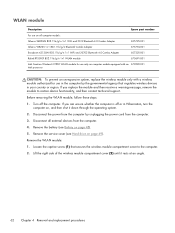
...only with a wireless module authorized for use in the computer by unplugging the power cord from the computer. 4. Remove the service cover (see Battery on page 48). 5. WLAN module Description Spare part number For use on all external devices from the computer. 3. Remove the WLAN module: 1.... devices in Hibernation, turn the computer on, and then shut it rests at an angle. 62 Chapter 4 Removal and replacement procedures Remove the battery (see Hard drive on page 49). Before removing the WLAN module, follow these steps: 1. If you replace the module and then receive a...
...only with a wireless module authorized for use in the computer by unplugging the power cord from the computer. 4. Remove the service cover (see Battery on page 48). 5. WLAN module Description Spare part number For use on all external devices from the computer. 3. Remove the WLAN module: 1.... devices in Hibernation, turn the computer on, and then shut it rests at an angle. 62 Chapter 4 Removal and replacement procedures Remove the battery (see Hard drive on page 49). Before removing the WLAN module, follow these steps: 1. If you replace the module and then receive a...

Maintenance and Service Guide
Page 73
... this procedure to the base enclosure. (The solid-state drive tilts up.) 2. If you are unsure whether the computer is off the computer. Remove the battery (see Battery on computer models equipped with an Intel processor) Spare part number 686927-001 Before removing the solid-state drive, follow these steps: 1.
... this procedure to the base enclosure. (The solid-state drive tilts up.) 2. If you are unsure whether the computer is off the computer. Remove the battery (see Battery on computer models equipped with an Intel processor) Spare part number 686927-001 Before removing the solid-state drive, follow these steps: 1.

Maintenance and Service Guide
Page 74
If you are unsure whether the computer is off the computer. Remove the battery (see Hard drive on page 49) b. Hard drive (see Battery on , and then shut it down through the operating system. 2. Disconnect the power from the computer by unplugging the power cord from the computer. 4. Turn ...
If you are unsure whether the computer is off the computer. Remove the battery (see Hard drive on page 49) b. Hard drive (see Battery on , and then shut it down through the operating system. 2. Disconnect the power from the computer by unplugging the power cord from the computer. 4. Turn ...

Maintenance and Service Guide
Page 78
... page 49) b. Disconnect all external devices from the computer. 3. Remove the battery (see Hard drive on page 48), and then remove the following components: a. Optical drive (see Top cover on , and then shut it down , with double-...
... page 49) b. Disconnect all external devices from the computer. 3. Remove the battery (see Hard drive on page 48), and then remove the following components: a. Optical drive (see Top cover on , and then shut it down , with double-...

Maintenance and Service Guide
Page 80
... is off the computer. Top cover (see Keyboard on page 66) Remove the fingerprint reader board: 1. Turn off or in the top cover. 3. Remove the battery (see Battery on , and then shut it down , with double-sided tape.) 72 Chapter 4 Removal and replacement procedures
... is off the computer. Top cover (see Keyboard on page 66) Remove the fingerprint reader board: 1. Turn off or in the top cover. 3. Remove the battery (see Battery on , and then shut it down , with double-sided tape.) 72 Chapter 4 Removal and replacement procedures


