
Wall Mounting Guide
Page 2
...equipment that is intended for home and other intellectual property rights. The information in this document is not furnished by copyright. HP assumes no responsibility for the use of our products for purposes other than those permitted by Macrovision. Use of this document...;2011 Hewlett-Packard Development Company, L.P. patents and other limited viewing uses only unless otherwise authorized by copyright law. No part of HP. Part number: 671405-001 Version 1.0 Nothing herein should be photocopied, reproduced, or translated to change without the prior written consent of...
...equipment that is intended for home and other intellectual property rights. The information in this document is not furnished by copyright. HP assumes no responsibility for the use of our products for purposes other than those permitted by Macrovision. Use of this document...;2011 Hewlett-Packard Development Company, L.P. patents and other limited viewing uses only unless otherwise authorized by copyright law. No part of HP. Part number: 671405-001 Version 1.0 Nothing herein should be photocopied, reproduced, or translated to change without the prior written consent of...
Wall Mounting Guide
Page 3
Table of contents 1 Preparing the computer for wall-mounting 1 What you need ...1 Safety information ...1 Preparing to remove the computer stand 2 Removing the computer stand ...2 2 Reinstalling the stand on the computer 9 What you need ...9 Safety information ...9 Removing the wall-mounting hardware 10 Replacing the computer stand 11 iii
Table of contents 1 Preparing the computer for wall-mounting 1 What you need ...1 Safety information ...1 Preparing to remove the computer stand 2 Removing the computer stand ...2 2 Reinstalling the stand on the computer 9 What you need ...9 Safety information ...9 Removing the wall-mounting hardware 10 Replacing the computer stand 11 iii
Wall Mounting Guide
Page 5
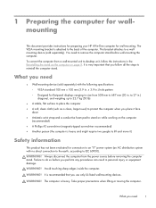
... or moving the computer. This bracket attaches to a wallmounting device (sold separately) with no direct connection to the earth, according to 27 in personal injury or equipment damage. to IEC 60950). The computer is very important that you need ● Wall-mounting device (sold... the computer. What you use only UL-listed wall-mounting devices. 1 Preparing the computer for wallmounting This document provides instructions for preparing your HP All-in . It is heavy. x 3.9 in.) hole pattern ◦ Designed for flat-panel displays ranging in size from a wall-mounted...
... or moving the computer. This bracket attaches to a wallmounting device (sold separately) with no direct connection to the earth, according to 27 in personal injury or equipment damage. to IEC 60950). The computer is very important that you need ● Wall-mounting device (sold... the computer. What you use only UL-listed wall-mounting devices. 1 Preparing the computer for wallmounting This document provides instructions for preparing your HP All-in . It is heavy. x 3.9 in.) hole pattern ◦ Designed for flat-panel displays ranging in size from a wall-mounted...
Wall Mounting Guide
Page 6
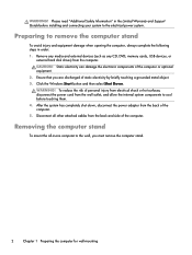
Remove any media and external devices (such as any CD, DVD, memory cards, USB devices, or external hard disk drives) from the wall outlet, and allow the internal system components to cool before installing and connecting your system to the electrical power system. Removing the computer stand To mount the all other attached cables from the back of static electricity by briefly touching a grounded metal object. 3. WARNING! Preparing to the wall, you are discharged of the computer. 5. Click the Windows Start button and then select Shut Down. After the system has completely shut down...
Remove any media and external devices (such as any CD, DVD, memory cards, USB devices, or external hard disk drives) from the wall outlet, and allow the internal system components to cool before installing and connecting your system to the electrical power system. Removing the computer stand To mount the all other attached cables from the back of static electricity by briefly touching a grounded metal object. 3. WARNING! Preparing to the wall, you are discharged of the computer. 5. Click the Windows Start button and then select Shut Down. After the system has completely shut down...

Wall Mounting Guide
Page 7
You might have to exert force to a desktop unit in Reinstalling the stand on the computer on a stable, flat surface that you can convert the computer back to release the cover. Removing the computer stand 3 Save the VESA cover. To remove the VESA cover, insert your finger into the slot just below the right bottom corner of the cover (1), and pry the cover off the computer (2). To reinstall the stand, follow all the steps in the future. NOTE: Save the VESA cover, the computer stand, and the six screws, so that is covered with a soft cloth. 2. Place the computer facedown on...
You might have to exert force to a desktop unit in Reinstalling the stand on the computer on a stable, flat surface that you can convert the computer back to release the cover. Removing the computer stand 3 Save the VESA cover. To remove the VESA cover, insert your finger into the slot just below the right bottom corner of the cover (1), and pry the cover off the computer (2). To reinstall the stand, follow all the steps in the future. NOTE: Save the VESA cover, the computer stand, and the six screws, so that is covered with a soft cloth. 2. Place the computer facedown on...

Wall Mounting Guide
Page 8
The sound occurs when the latch hooks on the back cover slide off the latch bases on the computer. 4 Chapter 1 Preparing the computer for wall-mounting NOTE: You might be a cracking sound as the back cover separates from the computer. Loosen the two screws at the center of the back cover. 4. These clicks indicate that secure the back cover to remove the back cover from the computer. If present, loosen the screw (1) at the bottom that the screw is sufficiently loosened. To remove the back cover from the computer, start lifting from the hole. Do not attempt to remove...
The sound occurs when the latch hooks on the back cover slide off the latch bases on the computer. 4 Chapter 1 Preparing the computer for wall-mounting NOTE: You might be a cracking sound as the back cover separates from the computer. Loosen the two screws at the center of the back cover. 4. These clicks indicate that secure the back cover to remove the back cover from the computer. If present, loosen the screw (1) at the bottom that the screw is sufficiently loosened. To remove the back cover from the computer, start lifting from the hole. Do not attempt to remove...

Wall Mounting Guide
Page 9
Save the stand. Removing the computer stand 5 Lift the stand slightly (1) and then disengage it from the computer. 5. Save the screws. 6. Remove the stand from the hook on the left and right of the computer. There are three screws each at the bottom left side (2). Remove the six screws that attach the stand to the computer.
Save the stand. Removing the computer stand 5 Lift the stand slightly (1) and then disengage it from the computer. 5. Save the screws. 6. Remove the stand from the hook on the left and right of the computer. There are three screws each at the bottom left side (2). Remove the six screws that attach the stand to the computer.

Wall Mounting Guide
Page 10
Remove the ring covers (1,2) from the lower center back of the computer. 6 Chapter 1 Preparing the computer for wall-mounting Snap the ring covers into place on the lower corners of the computer. 8. 7.
Remove the ring covers (1,2) from the lower center back of the computer. 6 Chapter 1 Preparing the computer for wall-mounting Snap the ring covers into place on the lower corners of the computer. 8. 7.

Wall Mounting Guide
Page 11
9. Tighten the two screws at the center of the computer to secure the back cover to the computer. If present, tighten the screw (1) at the bottom of the back cover. To replace the back cover, align the side and rear I/O openings on the back cover with the corresponding connectors on the computer. Press the cover so it snaps into place, and ensure that there are no gaps between the computer and the cover. 10. Removing the computer stand 7
9. Tighten the two screws at the center of the computer to secure the back cover to the computer. If present, tighten the screw (1) at the bottom of the back cover. To replace the back cover, align the side and rear I/O openings on the back cover with the corresponding connectors on the computer. Press the cover so it snaps into place, and ensure that there are no gaps between the computer and the cover. 10. Removing the computer stand 7

Wall Mounting Guide
Page 12
x 3.9 in . 11. Attach the wall-mounting hardware (purchased separately) according to the manufacturer's instructions to the wall. 8 Chapter 1 Preparing the computer for wall-mounting CAUTION: The computer is heavy and might require two people to mount it to the back of the computer, using the 100 mm x 100 mm (3.9 in .) screw holes.
x 3.9 in . 11. Attach the wall-mounting hardware (purchased separately) according to the manufacturer's instructions to the wall. 8 Chapter 1 Preparing the computer for wall-mounting CAUTION: The computer is heavy and might require two people to mount it to the back of the computer, using the 100 mm x 100 mm (3.9 in .) screw holes.
Wall Mounting Guide
Page 13
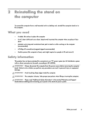
Always disconnect the computer from a wall-mounted unit to a desktop unit, reinstall the computer stand on to the computer. WARNING! The computer is heavy and might require two people to lift and move it) Safety information This product has not been evaluated for connection to an "IT" power system (an AC distribution system with no direct connection to the earth, according to the electrical power system. WARNING! Failure to do so before installing and connecting your system to IEC 60950). What you need 9 WARNING! What you need ● A stable, flat surface to ...
Always disconnect the computer from a wall-mounted unit to a desktop unit, reinstall the computer stand on to the computer. WARNING! The computer is heavy and might require two people to lift and move it) Safety information This product has not been evaluated for connection to an "IT" power system (an AC distribution system with no direct connection to the earth, according to the electrical power system. WARNING! Failure to do so before installing and connecting your system to IEC 60950). What you need 9 WARNING! What you need ● A stable, flat surface to ...
Wall Mounting Guide
Page 14
To reduce the risk of personal injury from electrical shock or hot surfaces, disconnect the power cord from the back of the computer. 4. Click the Windows Start button and then select Shut Down. CAUTION: Static electricity can damage the electronic components of static electricity by briefly touching a grounded metal object. 2. After the system has completely shut down, disconnect the power adapter from the wall outlet, and allow the internal system components to cool before touching them. 3. Disconnect all other attached cables from the wall. 6. CAUTION: The computer is heavy ...
To reduce the risk of personal injury from electrical shock or hot surfaces, disconnect the power cord from the back of the computer. 4. Click the Windows Start button and then select Shut Down. CAUTION: Static electricity can damage the electronic components of static electricity by briefly touching a grounded metal object. 2. After the system has completely shut down, disconnect the power adapter from the wall outlet, and allow the internal system components to cool before touching them. 3. Disconnect all other attached cables from the wall. 6. CAUTION: The computer is heavy ...

Wall Mounting Guide
Page 15
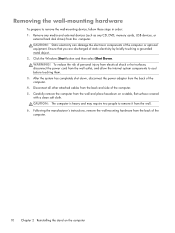
These clicks indicate that secure the back cover to remove the back cover from the computer. NOTE: You might be a cracking sound as the back cover separates from the lower left corner. If present, loosen the screw (1) at the bottom that the screw is sufficiently loosened. The sound occurs when the latch hooks on the back cover slide off the latch bases on the computer. Replacing the computer stand 11 Keep turning the screwdriver until you hear five clicks. To remove the back cover from the computer, start lifting from the computer. There might have to exert force to ...
These clicks indicate that secure the back cover to remove the back cover from the computer. NOTE: You might be a cracking sound as the back cover separates from the lower left corner. If present, loosen the screw (1) at the bottom that the screw is sufficiently loosened. The sound occurs when the latch hooks on the back cover slide off the latch bases on the computer. Replacing the computer stand 11 Keep turning the screwdriver until you hear five clicks. To remove the back cover from the computer, start lifting from the computer. There might have to exert force to ...

Wall Mounting Guide
Page 16
Remove the ring covers from the left and right side of the computer. 12 Chapter 2 Reinstalling the stand on the computer 3. Place the ring covers (1,2) back into their storage location at the center back of the computer. 4.
Remove the ring covers from the left and right side of the computer. 12 Chapter 2 Reinstalling the stand on the computer 3. Place the ring covers (1,2) back into their storage location at the center back of the computer. 4.

Wall Mounting Guide
Page 17
5. Replacing the computer stand 13 Install the three screws on the computer. 6. Engage the hook at the lower left on the computer with the slot on the stand (1), and place the stand back on the computer (2), aligning the screw holes on the stand with the screw holes on both the left and right side to secure the stand to the computer.
5. Replacing the computer stand 13 Install the three screws on the computer. 6. Engage the hook at the lower left on the computer with the slot on the stand (1), and place the stand back on the computer (2), aligning the screw holes on the stand with the screw holes on both the left and right side to secure the stand to the computer.

Wall Mounting Guide
Page 18
7. If present, tighten the screw (1) at the bottom of the computer to secure the back cover to the back of the back cover. 14 Chapter 2 Reinstalling the stand on the computer. Press the cover so it snaps into place, and ensure that there are no gaps between the computer and the cover. 8. To replace the back cover, align the side and rear I/O openings on the back cover with the corresponding connectors on the computer Tighten the two screws at the center of the computer.
7. If present, tighten the screw (1) at the bottom of the computer to secure the back cover to the back of the back cover. 14 Chapter 2 Reinstalling the stand on the computer. Press the cover so it snaps into place, and ensure that there are no gaps between the computer and the cover. 8. To replace the back cover, align the side and rear I/O openings on the back cover with the corresponding connectors on the computer Tighten the two screws at the center of the computer.

Wall Mounting Guide
Page 19
Connect the power cord. 12. Replacing the computer stand 15 Replace the VESA cover on the back of the computer. Connect any cables that were previously disconnected. 9. Place the computer in an upright position. 11. Be sure to align the tabs on the VESA cover with the slots on the back of the computer and snap the cover into place. 10.
Connect the power cord. 12. Replacing the computer stand 15 Replace the VESA cover on the back of the computer. Connect any cables that were previously disconnected. 9. Place the computer in an upright position. 11. Be sure to align the tabs on the VESA cover with the slots on the back of the computer and snap the cover into place. 10.

Watching and Recording TV
Page 1
Watching and Recording TV User Guide
Watching and Recording TV User Guide

Watching and Recording TV
Page 2
...States and/or other limited viewing uses only unless otherwise authorized by Macrovision, and is prohibited. Part Number: 610614-002 HP assumes no responsibility for the use of Microsoft Corporation in the express statements accompanying such products and services. Reverse engineering or...errors or omissions contained herein. Box 4010 Cupertino, CA 95015-4010 USA Copyright ©2011 Hewlett-Packard Development Company, L.P. HP supports lawful use of technology and does not endorse or encourage the use or reliability of Microsoft Corporation. The only warranties ...
...States and/or other limited viewing uses only unless otherwise authorized by Macrovision, and is prohibited. Part Number: 610614-002 HP assumes no responsibility for the use of Microsoft Corporation in the express statements accompanying such products and services. Reverse engineering or...errors or omissions contained herein. Box 4010 Cupertino, CA 95015-4010 USA Copyright ©2011 Hewlett-Packard Development Company, L.P. HP supports lawful use of technology and does not endorse or encourage the use or reliability of Microsoft Corporation. The only warranties ...

Watching and Recording TV
Page 3
... ...16 Recording TV ...17 Controlling TV playback 17 Watching Recorded TV Programs 18 TV Program Guide 18 Internet TV ...18 Watching and recording TV in HP TouchSmart 19 Setting up the TV signal 19 Watching Live TV ...19 Recording Live TV ...19 Setting Live TV to record a future broadcast 19 Watching...
... ...16 Recording TV ...17 Controlling TV playback 17 Watching Recorded TV Programs 18 TV Program Guide 18 Internet TV ...18 Watching and recording TV in HP TouchSmart 19 Setting up the TV signal 19 Watching Live TV ...19 Recording Live TV ...19 Setting Live TV to record a future broadcast 19 Watching...