Start Here
Page 7
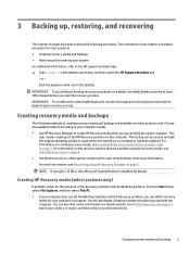
... to reinstall the original operating system in the taskbar. This step creates a backup of creating recovery media and backups are available using HP Recovery Manager on a tablet, the tablet battery must be used to the keyboard dock before you successfully set up , restoring, and.... Choose the available method according to your system from support. Click the question mark icon in cases where the hard drive is disabled by default. For more information, see Creating HP Recovery media (select products only) on -screen instructions. IMPORTANT: For a tablet with the computer...
... to reinstall the original operating system in the taskbar. This step creates a backup of creating recovery media and backups are available using HP Recovery Manager on a tablet, the tablet battery must be used to the keyboard dock before you successfully set up , restoring, and.... Choose the available method according to your system from support. Click the question mark icon in cases where the hard drive is disabled by default. For more information, see Creating HP Recovery media (select products only) on -screen instructions. IMPORTANT: For a tablet with the computer...

Hardware Reference Guide OMEN X
Page 15
The tool kit is located under the logo cover (3). Accessing the tool kit 9 Hex screws are used on the graphics card and system fans (radiators) ● Screws Pull the logo cover away from the case (1), and then disconnect the cable from the case (2). Accessing the tool kit The tool kit contains the following: ● Hard drive/power supply tool ● Screwdriver/wrench, one side Phillips, one side hex.
The tool kit is located under the logo cover (3). Accessing the tool kit 9 Hex screws are used on the graphics card and system fans (radiators) ● Screws Pull the logo cover away from the case (1), and then disconnect the cable from the case (2). Accessing the tool kit The tool kit contains the following: ● Hard drive/power supply tool ● Screwdriver/wrench, one side Phillips, one side hex.

Hardware Reference Guide OMEN X
Page 16
Replacing or installing drives The case offers four hard drive bays. The case supports three different drive types: ● 3.5 inch hard drive ● 2.5-inch solid-state drive ● U.2 drive NOTE: U.2 hard drives can be installed only in the upper-right drive bay. Note that the door remains connected to the left. Pull up on page 8). 2. Prepare the computer for disassembly (Preparing for disassembly on the right side of the hard drive door, and then rotate the door to the case. 10 Chapter 2 Hardware upgrades Installing a drive 1.
Replacing or installing drives The case offers four hard drive bays. The case supports three different drive types: ● 3.5 inch hard drive ● 2.5-inch solid-state drive ● U.2 drive NOTE: U.2 hard drives can be installed only in the upper-right drive bay. Note that the door remains connected to the left. Pull up on page 8). 2. Prepare the computer for disassembly (Preparing for disassembly on the right side of the hard drive door, and then rotate the door to the case. 10 Chapter 2 Hardware upgrades Installing a drive 1.

Hardware Reference Guide OMEN X
Page 17
Slide the drive cage latch to the left (1), and then use the pull tab to pull the drive cage out of the case (2). 4. Replacing or installing drives 11 To install a drive into the drive cage: a. 3.5-inch hard drive: Insert the drive into the drive cage using screws. All drives must first install the drive into a drive adapter bracket. 5. Screw locations are as follows: (1) 3.5-inch hard drive and U.2 drive (2) 2.5-inch solid-state drive NOTE: Before installing a U.2 drive into the drive cage, you must be secured into the drive cage, and then install four mounting screws. 3.
Slide the drive cage latch to the left (1), and then use the pull tab to pull the drive cage out of the case (2). 4. Replacing or installing drives 11 To install a drive into the drive cage: a. 3.5-inch hard drive: Insert the drive into the drive cage using screws. All drives must first install the drive into a drive adapter bracket. 5. Screw locations are as follows: (1) 3.5-inch hard drive and U.2 drive (2) 2.5-inch solid-state drive NOTE: Before installing a U.2 drive into the drive cage, you must be secured into the drive cage, and then install four mounting screws. 3.

Hardware Reference Guide OMEN X
Page 20
7. Rotate the hard drive door to the new hard drive. 1. Removing a drive IMPORTANT: Before you remove a hard drive, be sure to back up on page 8). 2. Prepare the computer for disassembly (Preparing for disassembly on the right side of the hard drive door, and then rotate the door to the case. 14 Chapter 2 Hardware upgrades Pull up the data from the hard drive so that the door remains connected to the left. Note that you can transfer the data to the right and press down until it snaps into place.
7. Rotate the hard drive door to the new hard drive. 1. Removing a drive IMPORTANT: Before you remove a hard drive, be sure to back up on page 8). 2. Prepare the computer for disassembly (Preparing for disassembly on the right side of the hard drive door, and then rotate the door to the case. 14 Chapter 2 Hardware upgrades Pull up the data from the hard drive so that the door remains connected to the left. Note that you can transfer the data to the right and press down until it snaps into place.

Hardware Reference Guide OMEN X
Page 21
To remove a drive from the drive cage: a. 3.5-inch hard drive: Remove the four mounting screws (1) from the sides of the cage, and then lift the drive out of the case (2). 4. Slide the drive cage latch to the left (1), and then use the pull tab to pull the drive cage out of the cage (2). 3. Replacing or installing drives 15
To remove a drive from the drive cage: a. 3.5-inch hard drive: Remove the four mounting screws (1) from the sides of the cage, and then lift the drive out of the case (2). 4. Slide the drive cage latch to the left (1), and then use the pull tab to pull the drive cage out of the cage (2). 3. Replacing or installing drives 15

Hardware Reference Guide OMEN X
Page 23
... remains connected to the left . Pull up on page 9) into the drive cage until it is not accessible, slide the drive cage latch to the case. 2. Drive security You can insert the hard drive pull tab into the drive cage to the left (1), insert the security tool from the outside of...
... remains connected to the left . Pull up on page 9) into the drive cage until it is not accessible, slide the drive cage latch to the case. 2. Drive security You can insert the hard drive pull tab into the drive cage to the left (1), insert the security tool from the outside of...
Hardware Reference Guide OMEN X
Page 28
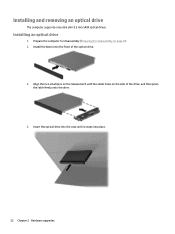
Installing an optical drive 1. Align the two small pins on the release latch with the small holes on page 8). 2. Prepare the computer for disassembly (Preparing for disassembly on the side of the optical drive. 3. Insert the optical drive into the case until it snaps into place. 22 Chapter 2 Hardware upgrades Installing and removing an optical drive The computer supports only ultra slim 9.5 mm SATA optical drives. Install the bezel onto the front of the drive, and then press the latch firmly onto the drive. 4.
Installing an optical drive 1. Align the two small pins on the release latch with the small holes on page 8). 2. Prepare the computer for disassembly (Preparing for disassembly on the side of the optical drive. 3. Insert the optical drive into the case until it snaps into place. 22 Chapter 2 Hardware upgrades Installing and removing an optical drive The computer supports only ultra slim 9.5 mm SATA optical drives. Install the bezel onto the front of the drive, and then press the latch firmly onto the drive. 4.

Hardware Reference Guide OMEN X
Page 29
... pressing the release button ejects the drive. 6. NOTE: The latch on the outside of the computer case, insert a screwdriver into the hole in on the release button (2). Remove the optical drive from the case (3). Eject the optical drive tray by inserting a paper clip into the right side of the release latch... and press the latch toward the left (1). Remove the access panel (Removing and replacing the access panel on page 8). 2. On the outside of the case, use a pointed tool to press in the optical drive and pressing inward. 4. Installing and removing an optical drive 23
... pressing the release button ejects the drive. 6. NOTE: The latch on the outside of the computer case, insert a screwdriver into the hole in on the release button (2). Remove the optical drive from the case (3). Eject the optical drive tray by inserting a paper clip into the right side of the release latch... and press the latch toward the left (1). Remove the access panel (Removing and replacing the access panel on page 8). 2. On the outside of the case, use a pointed tool to press in the optical drive and pressing inward. 4. Installing and removing an optical drive 23

Hardware Reference Guide OMEN X
Page 30
Locate the a vacant expansion socket on the system board and the corresponding expansion slot on the back of the case (2). b. Install two screws into the expansion socket (1). e. To install a graphics card fan: 24 Chapter 2 Hardware upgrades Remove the access panel (Removing and... graphics card: a. Remove the expansion slot cover by removing the screw at the top of the cover (1), and then lifting the cover out of the case. Insert a graphics card into the left side of the graphics card (2). c. Prepare the computer for disassembly (Preparing for disassembly on page 18). 3. ...
Locate the a vacant expansion socket on the system board and the corresponding expansion slot on the back of the case (2). b. Install two screws into the expansion socket (1). e. To install a graphics card fan: 24 Chapter 2 Hardware upgrades Remove the access panel (Removing and... graphics card: a. Remove the expansion slot cover by removing the screw at the top of the cover (1), and then lifting the cover out of the case. Insert a graphics card into the left side of the graphics card (2). c. Prepare the computer for disassembly (Preparing for disassembly on page 18). 3. ...

Hardware Reference Guide OMEN X
Page 31
Remove the cover from the tool kit (Accessing the tool kit on the outer wall (1). c. d. From the outside of the case, insert the fan into place on page 9). Replace the cover (3). 5. Replace the access panel. a. From the inside of the case, install four screws (2) with the screwdriver/wrench from the location where you will install the graphics card fan. Installing graphics cards 25 b.
Remove the cover from the tool kit (Accessing the tool kit on the outer wall (1). c. d. From the outside of the case, insert the fan into place on page 9). Replace the cover (3). 5. Replace the access panel. a. From the inside of the case, install four screws (2) with the screwdriver/wrench from the location where you will install the graphics card fan. Installing graphics cards 25 b.

Hardware Reference Guide OMEN X
Page 32
... enough to access the cables underneath. From the outside of the case, remove the four screws (2) that connect to the front bezel. b. You must remove...: a. Removing the PCI fan The PCI fan is secured to the front of the case, disconnect the fan cable from the system board (1). Remove the fan filter by sliding the filter out from the...Removing and replacing the access panel on page 8). 2. Note that there are two cables that secure the fan to the case. 26 Chapter 2 Hardware upgrades b. To remove the front bezel: a. Prepare the computer for disassembly (Preparing for the ...
... enough to access the cables underneath. From the outside of the case, remove the four screws (2) that connect to the front bezel. b. You must remove...: a. Removing the PCI fan The PCI fan is secured to the front of the case, disconnect the fan cable from the system board (1). Remove the fan filter by sliding the filter out from the...Removing and replacing the access panel on page 8). 2. Note that there are two cables that secure the fan to the case. 26 Chapter 2 Hardware upgrades b. To remove the front bezel: a. Prepare the computer for disassembly (Preparing for the ...

Hardware Reference Guide OMEN X
Page 33
To replace the PCI fan, reverse the removal procedures. Lift the fan out of the case (3). Removing the PCI fan 27 c.
To replace the PCI fan, reverse the removal procedures. Lift the fan out of the case (3). Removing the PCI fan 27 c.

Hardware Reference Guide OMEN X
Page 34
... upgrades Connect all other internal components. 8. Installing a system board The system board is secured to the right (2), and then lift the tray out of the case (3). 4. You must remove the tray before you can remove or install a system board. 1. Install any graphics cards. 7. Remove the access panel (Removing and replacing the... install the system board, position the system board atop the system board tray, and then install the eight screws that secure the tray to the case (1), slide the tray to a system board tray. Replace the system board tray assembly in the...
... upgrades Connect all other internal components. 8. Installing a system board The system board is secured to the right (2), and then lift the tray out of the case (3). 4. You must remove the tray before you can remove or install a system board. 1. Install any graphics cards. 7. Remove the access panel (Removing and replacing the... install the system board, position the system board atop the system board tray, and then install the eight screws that secure the tray to the case (1), slide the tray to a system board tray. Replace the system board tray assembly in the...

Hardware Reference Guide OMEN X
Page 35
... (Removing and replacing the access panel on page 28). 4. Removing the hard drive fan The hard drive fan is secured to the rear of the case (2). b. To replace the hard drive fan, reverse the removal procedures. Remove the system board tray (Installing a system board on page 18). 3. c. ...Removing the hard drive fan 29 Lift the fan out of the case under the system board tray. From the outside of the case, remove the four screws (1) that secure the fan to the case. Prepare the computer for disassembly (Preparing for disassembly on page 8). 2. From the outside...
... (Removing and replacing the access panel on page 28). 4. Removing the hard drive fan The hard drive fan is secured to the rear of the case (2). b. To replace the hard drive fan, reverse the removal procedures. Remove the system board tray (Installing a system board on page 18). 3. c. ...Removing the hard drive fan 29 Lift the fan out of the case under the system board tray. From the outside of the case, remove the four screws (1) that secure the fan to the case. Prepare the computer for disassembly (Preparing for disassembly on page 8). 2. From the outside...

Hardware Reference Guide OMEN X
Page 36
... rear of the computer power supply. 1. CAUTION: To prevent damage, the overall power consumption of the computer must not exceed the maximum rating of the case. CAUTION: To avoid damaging the cover, pry only on page 18). 3. Prepare the computer for disassembly (Preparing for disassembly on page 28). 4. Remove the access... supports power supplies that follow the ATX standard with a maximum of the cover as shown in the following image. 5. Route the power cables into the case, and then insert the power supply (1). 30 Chapter 2 Hardware upgrades
... rear of the computer power supply. 1. CAUTION: To prevent damage, the overall power consumption of the computer must not exceed the maximum rating of the case. CAUTION: To avoid damaging the cover, pry only on page 18). 3. Prepare the computer for disassembly (Preparing for disassembly on page 28). 4. Remove the access... supports power supplies that follow the ATX standard with a maximum of the cover as shown in the following image. 5. Route the power cables into the case, and then insert the power supply (1). 30 Chapter 2 Hardware upgrades

Hardware Reference Guide OMEN X
Page 37
Place the connector into the power supply (4). Installing a power supply 31 Install the green ground wire onto the remaining power supply screw (3). 7. NOTE: You will install one other screw in the next step to the case (2). d. Install the connector hex screw (2) using the wrench/screwdriver from the tool kit. Plug the cable into the corner of the power supply bay (1). Install three screws to secure the power supply to secure the grounding wire. 8. b. To install the power supply connector cable into the case: a. c.
Place the connector into the power supply (4). Installing a power supply 31 Install the green ground wire onto the remaining power supply screw (3). 7. NOTE: You will install one other screw in the next step to the case (2). d. Install the connector hex screw (2) using the wrench/screwdriver from the tool kit. Plug the cable into the corner of the power supply bay (1). Install three screws to secure the power supply to secure the grounding wire. 8. b. To install the power supply connector cable into the case: a. c.

Hardware Reference Guide OMEN X
Page 38
Connect the power supply SATA cables (1) and I /O board) are labeled to indicate components they connect to the power supply. Replace the power supply cover. 11. Replace the system board tray assembly. 32 Chapter 2 Hardware upgrades The cables in the computer case are available to connect to . Six SATA power cables (four hard drive + one U.2 drive + one optical drive) and one PATA power connector (from the I /O board and cable (2). CAUTION: To avoid damaging the cable, pull the tab or connector instead of the cable itself. 10. 9.
Connect the power supply SATA cables (1) and I /O board) are labeled to indicate components they connect to the power supply. Replace the power supply cover. 11. Replace the system board tray assembly. 32 Chapter 2 Hardware upgrades The cables in the computer case are available to connect to . Six SATA power cables (four hard drive + one U.2 drive + one optical drive) and one PATA power connector (from the I /O board and cable (2). CAUTION: To avoid damaging the cable, pull the tab or connector instead of the cable itself. 10. 9.
Hardware Reference Guide OMEN X
Page 39
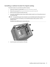
...positions shown in the following image. Installation location (3) is present in select models only. 5. Insert the bracket onto the inside rear of the case. 4. NOTE: On models that support two brackets, you can install the brackets in either position 1 or 2. On models that support only one... bracket, you want to the side of the case. Remove the access panel (Removing and replacing the access panel on page 8). 2. If you can accommodate only 240 mm radiators. 1. Installing a...
...positions shown in the following image. Installation location (3) is present in select models only. 5. Insert the bracket onto the inside rear of the case. 4. NOTE: On models that support two brackets, you can install the brackets in either position 1 or 2. On models that support only one... bracket, you want to the side of the case. Remove the access panel (Removing and replacing the access panel on page 8). 2. If you can accommodate only 240 mm radiators. 1. Installing a...

Hardware Reference Guide OMEN X
Page 40
Remove and clean the air filters on page 18). 3. Remove the access panel (Removing and replacing the access panel on all vented sides of the computer. 34 Chapter 2 Hardware upgrades Install any needed fans. Prepare the computer for disassembly (Preparing for disassembly on page 9) to secure the bracket to the case. 7. Cleaning filters 1. Install the eight hex screws using the wrench/screwdriver from the tool kit (Accessing the tool kit on page 8). 2. 6.
Remove and clean the air filters on page 18). 3. Remove the access panel (Removing and replacing the access panel on all vented sides of the computer. 34 Chapter 2 Hardware upgrades Install any needed fans. Prepare the computer for disassembly (Preparing for disassembly on page 9) to secure the bracket to the case. 7. Cleaning filters 1. Install the eight hex screws using the wrench/screwdriver from the tool kit (Accessing the tool kit on page 8). 2. 6.


