
HP Compaq nc2400 Notebook PC - Getting Started - Enhanced for Accessibility Windows Vista
Page 60
... 3-7 display release latch, identifying A-6 display, switching image 3-3 docking connector A-7 drive light A-6 drive light, identifying A-6 drive, optical A-8 E embedded numeric keypad, identifying A-3 environmental specifications D-1 esc key, identifying A-3 expansion memory module compartment, identifying A-9 external devices, troubleshooting 3-7 external monitor port, identifying A-7 F fingerprint reader A-2 firewalls 2-4 fn key, identifying A-3 function keys, identifying A-3 H hard drive bay, identifying A-9 headphone jack A-7 Help and Support 3-9 Hibernation...
... 3-7 display release latch, identifying A-6 display, switching image 3-3 docking connector A-7 drive light A-6 drive light, identifying A-6 drive, optical A-8 E embedded numeric keypad, identifying A-3 environmental specifications D-1 esc key, identifying A-3 expansion memory module compartment, identifying A-9 external devices, troubleshooting 3-7 external monitor port, identifying A-7 F fingerprint reader A-2 firewalls 2-4 fn key, identifying A-3 function keys, identifying A-3 H hard drive bay, identifying A-9 headphone jack A-7 Help and Support 3-9 Hibernation...

HP Compaq nc2400 Notebook PC - Maintenance and Service Guide
Page 5
... Replacement Preliminaries 4.1 Tools Required 4-1 4.2 Service Considerations 4-2 Plastic Parts 4-2 Cables and Connectors 4-2 4.3 Preventing Damage to Removable Drives 4-3 4.4 Preventing Electrostatic Damage 4-4 4.5 Packaging and Transporting Precautions 4-5 4.6 Workstation Precautions 4-6 4.7 Grounding Equipment and Methods 4-7 5 Removal and Replacement Procedures 5.1 Serial Number 5-2 5.2 Disassembly Sequence Chart 5-3 5.3 Preparing the Computer for Disassembly 5-5 5.4 Hard Drive 5-7 5.5 Computer Feet 5-11 5.6 External Memory Module 5-12 5.7 Mini Card...
... Replacement Preliminaries 4.1 Tools Required 4-1 4.2 Service Considerations 4-2 Plastic Parts 4-2 Cables and Connectors 4-2 4.3 Preventing Damage to Removable Drives 4-3 4.4 Preventing Electrostatic Damage 4-4 4.5 Packaging and Transporting Precautions 4-5 4.6 Workstation Precautions 4-6 4.7 Grounding Equipment and Methods 4-7 5 Removal and Replacement Procedures 5.1 Serial Number 5-2 5.2 Disassembly Sequence Chart 5-3 5.3 Preparing the Computer for Disassembly 5-5 5.4 Hard Drive 5-7 5.5 Computer Feet 5-11 5.6 External Memory Module 5-12 5.7 Mini Card...

HP Compaq nc2400 Notebook PC - Maintenance and Service Guide
Page 87
... discharged of static electricity. While handling a drive, avoid touching the connector. ■ Handle drives on , and then shut it in a bubble pack mailer or other suitable form of shock-proof foam. ■ Avoid dropping drives from any height onto any surface. ■ After removing a hard drive, an optical drive, or a diskette drive, place it down the computer. If...
... discharged of static electricity. While handling a drive, avoid touching the connector. ■ Handle drives on , and then shut it in a bubble pack mailer or other suitable form of shock-proof foam. ■ Avoid dropping drives from any height onto any surface. ■ After removing a hard drive, an optical drive, or a diskette drive, place it down the computer. If...
HP Compaq nc2400 Notebook PC - Maintenance and Service Guide
Page 95
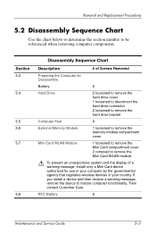
... 0 Maintenance and Service Guide 5-3 Section 5.3 5.4 5.5 5.6 5.7 5.8 Disassembly Sequence Chart Description # of Screws Removed Preparing the Computer for Disassembly Battery 0 Hard Drive 2 loosened to remove the hard drive cover 1 loosened to disconnect the hard drive connector 2 loosened to remove the hard drive bracket Computer Feet 0 External Memory Module 1 loosened to remove the memory module compartment cover Mini Card WLAN Module 1 loosened...
... 0 Maintenance and Service Guide 5-3 Section 5.3 5.4 5.5 5.6 5.7 5.8 Disassembly Sequence Chart Description # of Screws Removed Preparing the Computer for Disassembly Battery 0 Hard Drive 2 loosened to remove the hard drive cover 1 loosened to disconnect the hard drive connector 2 loosened to remove the hard drive bracket Computer Feet 0 External Memory Module 1 loosened to remove the memory module compartment cover Mini Card WLAN Module 1 loosened...

HP Compaq nc2400 Notebook PC - Maintenance and Service Guide
Page 100
Loosen the Phillips PM2.0×5.0 hard drive retention screw 1. 6. Disconnect the hard drive connector 2 from the system board. Removal and Replacement Procedures 5. Removing the Hard Drive 5-8 Maintenance and Service Guide
Loosen the Phillips PM2.0×5.0 hard drive retention screw 1. 6. Disconnect the hard drive connector 2 from the system board. Removal and Replacement Procedures 5. Removing the Hard Drive 5-8 Maintenance and Service Guide
HP Compaq nc2400 Notebook PC - Maintenance and Service Guide
Page 150
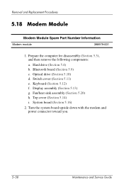
...Hard drive (Section 5.4) b. Switch cover (Section 5.11) e. Removal and Replacement Procedures 5.18 Modem Module Modem Module Spare Part Number Information Modem module 398979-001 1. Keyboard (Section 5.12) f. Display assembly (Section 5.13) g. Turn the system board upside down with the modem and power connector... toward you. 5-58 Maintenance and Service Guide Optical drive (Section 5.10) d. System board (Section 5.16) 2. Top cover (Section 5.14) i. Bluetooth board (Section 5.9)...
...Hard drive (Section 5.4) b. Switch cover (Section 5.11) e. Removal and Replacement Procedures 5.18 Modem Module Modem Module Spare Part Number Information Modem module 398979-001 1. Keyboard (Section 5.12) f. Display assembly (Section 5.13) g. Turn the system board upside down with the modem and power connector... toward you. 5-58 Maintenance and Service Guide Optical drive (Section 5.10) d. System board (Section 5.16) 2. Top cover (Section 5.14) i. Bluetooth board (Section 5.9)...

HP Compaq nc2400 Notebook PC - Maintenance and Service Guide
Page 173
documented in Section 5.4) Phillips PM2.0×5.0 Screw Locations Maintenance and Service Guide A-3 Screw Listing Table A-1 Phillips PM2.0×5.0 Screw (Continued) Head mm Color Qty. Length Thread Width Black 8 5.0 mm 2.0 mm 5.0 mm Where used: 1 One screw that secure the hard drive bracket to the system board (screw is captured on the bracket by a C-clip; documented in Section 5.4) 2 Two screws that secures the hard drive connector to the computer (screws are captured on the connector by C-clips;
documented in Section 5.4) Phillips PM2.0×5.0 Screw Locations Maintenance and Service Guide A-3 Screw Listing Table A-1 Phillips PM2.0×5.0 Screw (Continued) Head mm Color Qty. Length Thread Width Black 8 5.0 mm 2.0 mm 5.0 mm Where used: 1 One screw that secure the hard drive bracket to the system board (screw is captured on the bracket by a C-clip; documented in Section 5.4) 2 Two screws that secures the hard drive connector to the computer (screws are captured on the connector by C-clips;
Routine Care
Page 8
...connector pins on a removable drive or on the keyboard or move the computer while the drive is the only source of the drive. do not drop or compress the drive. When the battery pack is writing to a medium. For additional information, access the Disk Defragmenter online Help. Using Disk Cleanup Disk Cleanup searches the hard... disk for unnecessary files that the battery pack is sensitive to vibration. Drives Drives are fragile components that it can safely delete to free up disk space and help...
...connector pins on a removable drive or on the keyboard or move the computer while the drive is the only source of the drive. do not drop or compress the drive. When the battery pack is writing to a medium. For additional information, access the Disk Defragmenter online Help. Using Disk Cleanup Disk Cleanup searches the hard... disk for unnecessary files that the battery pack is sensitive to vibration. Drives Drives are fragile components that it can safely delete to free up disk space and help...
Routine Care - Windows Vista
Page 8
... > All Programs > Accessories > System Tools > Disk Defragmenter. 2. To run Disk Defragmenter: 1. do not drop or compress the drive. Do not use the computer, the hard disk files become fragmented. To run Disk Cleanup: 1. For additional information, access the Disk Defragmenter online Help. Select Start > All Programs... delete to free up disk space and help the computer to media. Click Defragment now. Do not touch the connector pins on a removable drive or on the hard disk so that must be handled carefully. Do not type on the screen. 4 Chapter 1 Hardware maintenance ENWW ...
... > All Programs > Accessories > System Tools > Disk Defragmenter. 2. To run Disk Defragmenter: 1. do not drop or compress the drive. Do not use the computer, the hard disk files become fragmented. To run Disk Cleanup: 1. For additional information, access the Disk Defragmenter online Help. Select Start > All Programs... delete to free up disk space and help the computer to media. Click Defragment now. Do not touch the connector pins on a removable drive or on the hard disk so that must be handled carefully. Do not type on the screen. 4 Chapter 1 Hardware maintenance ENWW ...

Drives
Page 5
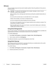
...of power, ensure that check carry-on the keyboard or move a computer or external hard drive from one location to another. CAUTION To reduce the risk of damage to the computer, damage to a drive, or loss of information, observe these precautions: Initiate standby, and allow the screen... use x-rays instead of the drive. ENWW 1 Do not touch the connector pins on a removable drive or on , and then shut it with magnetic fields include airport walk-through the operating system. Avoid exposing a drive to which they apply. 1 Drive care Drives are fragile computer components that must...
...of power, ensure that check carry-on the keyboard or move a computer or external hard drive from one location to another. CAUTION To reduce the risk of damage to the computer, damage to a drive, or loss of information, observe these precautions: Initiate standby, and allow the screen... use x-rays instead of the drive. ENWW 1 Do not touch the connector pins on a removable drive or on , and then shut it with magnetic fields include airport walk-through the operating system. Avoid exposing a drive to which they apply. 1 Drive care Drives are fragile computer components that must...

Drives
Page 12
10. Remove the hard drive retention bracket (2). 11. Remove the hard drive cable connector screw (1). 12. Gently pull the end of the hard drive cable up to release the cable from the hard drive cable connector (2). 8 Chapter 3 Hard drives ENWW
10. Remove the hard drive retention bracket (2). 11. Remove the hard drive cable connector screw (1). 12. Gently pull the end of the hard drive cable up to release the cable from the hard drive cable connector (2). 8 Chapter 3 Hard drives ENWW

Drives
Page 13
13. Lift the hard drive away from the computer. Insert the hard drive into place. Align the end of the hard drive cable with the hard drive cable connector (1) and press down gently until the hard drive cable snaps into the hard drive bay until it is fully seated. 2. ENWW Replacing the hard drive 9 To install a hard drive: 1.
13. Lift the hard drive away from the computer. Insert the hard drive into place. Align the end of the hard drive cable with the hard drive cable connector (1) and press down gently until the hard drive cable snaps into the hard drive bay until it is fully seated. 2. ENWW Replacing the hard drive 9 To install a hard drive: 1.

Drives
Page 14
Replace the hard drive retention bracket (1). 5. Align the tabs (1) on the hard drive cover with the notches on the computer. 7. Tighten the hard drive retention bracket screws (2). 6. Close the cover (2). 10 Chapter 3 Hard drives ENWW Replace the hard drive cable connector screw (2). 4. 3.
Replace the hard drive retention bracket (1). 5. Align the tabs (1) on the hard drive cover with the notches on the computer. 7. Tighten the hard drive retention bracket screws (2). 6. Close the cover (2). 10 Chapter 3 Hard drives ENWW Replace the hard drive cable connector screw (2). 4. 3.

Drives - Windows Vista
Page 5
... or humidity extremes. Refer to the following cautions before writing to media. Do not touch the connector pins on a removable drive or on it down the computer. Handle a drive carefully; When the battery is the only source of information, observe these precautions: Before you are... move a computer or external hard drive from the drive bay, or traveling with, shipping, or storing a drive. Security devices with cleaning products. CAUTION To reduce the risk of damage to the computer, damage to a drive, or loss of power, be mailed, place the drive in Hibernation, turn the computer...
... or humidity extremes. Refer to the following cautions before writing to media. Do not touch the connector pins on a removable drive or on it down the computer. Handle a drive carefully; When the battery is the only source of information, observe these precautions: Before you are... move a computer or external hard drive from the drive bay, or traveling with, shipping, or storing a drive. Security devices with cleaning products. CAUTION To reduce the risk of damage to the computer, damage to a drive, or loss of power, be mailed, place the drive in Hibernation, turn the computer...

Drives - Windows Vista
Page 11
Remove the hard drive cable connector screw (1). 12. 10. ENWW Replacing the hard drive 7 Gently pull the end of the hard drive cable up to release the cable from the hard drive cable connector (2). Remove the hard drive retention bracket (2). 11.
Remove the hard drive cable connector screw (1). 12. 10. ENWW Replacing the hard drive 7 Gently pull the end of the hard drive cable up to release the cable from the hard drive cable connector (2). Remove the hard drive retention bracket (2). 11.

Drives - Windows Vista
Page 12
Insert the hard drive into place. 8 Chapter 3 Hard drives ENWW To install a hard drive: 1. Lift the hard drive away from the computer. Align the end of the hard drive cable with the hard drive cable connector (1) and press down gently until the hard drive cable snaps into the hard drive bay until it is fully seated. 2. 13.
Insert the hard drive into place. 8 Chapter 3 Hard drives ENWW To install a hard drive: 1. Lift the hard drive away from the computer. Align the end of the hard drive cable with the hard drive cable connector (1) and press down gently until the hard drive cable snaps into the hard drive bay until it is fully seated. 2. 13.

Drives - Windows Vista
Page 13
Replace the hard drive retention bracket (1). 5. ENWW Replacing the hard drive 9 Tighten the hard drive retention bracket screws (2). 6. Close the cover (2). Replace the hard drive cable connector screw (2). 4. Align the tabs (1) on the hard drive cover with the notches on the computer. 7. 3.
Replace the hard drive retention bracket (1). 5. ENWW Replacing the hard drive 9 Tighten the hard drive retention bracket screws (2). 6. Close the cover (2). Replace the hard drive cable connector screw (2). 4. Align the tabs (1) on the hard drive cover with the notches on the computer. 7. 3.
Notebook Tour
Page 25
... identifying 17 battery pack charge information 7 battery pack release latch 13 bays battery 13, 18 Bluetooth device 13 hard drive 13 Bluetooth compartment 13 Bluetooth label 18 business card holder 13 buttons mute 5 power 5 wireless 5 C cable RJ-11 (modem) 17 caps lock light... 7 display release latch 8, 15 display switch 15 docking connector 10, 11 drive light 3, 8 drives hard 13 optical 12 E environmental specifications 19 external monitor port 10, 11 F fingerprint reader 5 fn key identifying 6 function keys identifying 6 H hard drive bay, identifying 13 headphone (audio-out) jack 10, 11...
... identifying 17 battery pack charge information 7 battery pack release latch 13 bays battery 13, 18 Bluetooth device 13 hard drive 13 Bluetooth compartment 13 Bluetooth label 18 business card holder 13 buttons mute 5 power 5 wireless 5 C cable RJ-11 (modem) 17 caps lock light... 7 display release latch 8, 15 display switch 15 docking connector 10, 11 drive light 3, 8 drives hard 13 optical 12 E environmental specifications 19 external monitor port 10, 11 F fingerprint reader 5 fn key identifying 6 function keys identifying 6 H hard drive bay, identifying 13 headphone (audio-out) jack 10, 11...
Notebook Tour - Windows Vista
Page 25
... identifying 17 battery pack charge information 7 battery pack release latch 13 bays battery 13, 18 Bluetooth device 14 hard drive 13 Bluetooth compartment 14 Bluetooth label 18 business card holder 13 buttons mute 5 power 5 wireless 5 C cable RJ-11 (modem) 17 caps lock light... 7 display release latch 8, 15 display switch 15 docking connector 10, 11 drive light 3, 8 drives hard 13 optical 12 E environmental specifications 19 external monitor port 10, 11 F fingerprint reader 5 fn key identifying 6 function keys identifying 6 H hard drive bay, identifying 13 headphone (audio-out) jack 10, 11...
... identifying 17 battery pack charge information 7 battery pack release latch 13 bays battery 13, 18 Bluetooth device 14 hard drive 13 Bluetooth compartment 14 Bluetooth label 18 business card holder 13 buttons mute 5 power 5 wireless 5 C cable RJ-11 (modem) 17 caps lock light... 7 display release latch 8, 15 display switch 15 docking connector 10, 11 drive light 3, 8 drives hard 13 optical 12 E environmental specifications 19 external monitor port 10, 11 F fingerprint reader 5 fn key identifying 6 function keys identifying 6 H hard drive bay, identifying 13 headphone (audio-out) jack 10, 11...

HP Compaq nc2400 Notebook PC - Getting Started- Enhanced for Accessibility
Page 64
... 3-7 display release latch, identifying A-6 display, switching image 3-3 docking connector A-7 drive light A-6 drive light, identifying A-6 drive, optical A-8 E embedded numeric keypad, identifying A-3 environmental specifications D-1 esc key, identifying A-3 expansion memory module compartment, identifying A-9 external devices, troubleshooting 3-7 external monitor port, identifying A-7 F fingerprint reader A-2 firewalls 2-4 fn key, identifying A-3 function keys, identifying A-3 H hard drive bay, identifying A-9 headphone jack A-7 Help and Support Center...
... 3-7 display release latch, identifying A-6 display, switching image 3-3 docking connector A-7 drive light A-6 drive light, identifying A-6 drive, optical A-8 E embedded numeric keypad, identifying A-3 environmental specifications D-1 esc key, identifying A-3 expansion memory module compartment, identifying A-9 external devices, troubleshooting 3-7 external monitor port, identifying A-7 F fingerprint reader A-2 firewalls 2-4 fn key, identifying A-3 function keys, identifying A-3 H hard drive bay, identifying A-9 headphone jack A-7 Help and Support Center...


