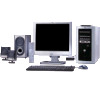
HP Media Center m490k Research
View Results Below
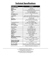
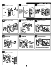
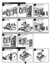
Free HP Media Center m490k manuals!
Problems with HP Media Center m490k?
Ask a Question
Free HP Media Center m490k manuals!
Problems with HP Media Center m490k?
Ask a Question
Related Manual Pages

Similar Questions

How Do I Turn On Wireless On My Hp Media Center Pc M8000
(Posted by parriya 10 years ago)

Why Does The Z820 Need A 2nd Cpu To Be Able To Use Pcie Slot #4?
This feature is mentioned here: http://h18004.www1.hp.com/products/quickspecs/14264_na/14264_na.pdf
This feature is mentioned here: http://h18004.www1.hp.com/products/quickspecs/14264_na/14264_na.pdf
(Posted by maschoen 11 years ago)

I Have An Hp Jet 6600 Printer How Do I Print Using Black Cartrige Only?
I have an hp jet 6600 printer how do i print using black cartrige only? this is so frustrating, I me...
I have an hp jet 6600 printer how do i print using black cartrige only? this is so frustrating, I me...
(Posted by gideonbrothers 11 years ago)