
Service Manual
Page 55
... the video controller, the printer enters the INTR period immediately after the end of the LSTR period. 58 Functional Overview C4224-90962 Also to -formatter connector (J201) forms a link that operates as a serial data bus. When the pick-up command is installed or From the power-ON until the pick-up...
... the video controller, the printer enters the INTR period immediately after the end of the LSTR period. 58 Functional Overview C4224-90962 Also to -formatter connector (J201) forms a link that operates as a serial data bus. When the pick-up command is installed or From the power-ON until the pick-up...

Service Manual
Page 61
Document scanner removal Figure 4-2 Removing the optional scanner unit 1 Rotate the document scanner latch down and to the right to the "open" position. 2 Pull out on the bottom of the document scanner unit, then push it up slowly to clear the connector at the top of the scanner. 3 Lift the scanner off. 4 Move the scanner latch back to the "closed" position. C4224-90962 External assemblies and covers 65
Document scanner removal Figure 4-2 Removing the optional scanner unit 1 Rotate the document scanner latch down and to the right to the "open" position. 2 Pull out on the bottom of the document scanner unit, then push it up slowly to clear the connector at the top of the scanner. 3 Lift the scanner off. 4 Move the scanner latch back to the "closed" position. C4224-90962 External assemblies and covers 65

Service Manual
Page 64
Contact image sensor removal (continued) NOTE: Figure 4-5 Removing the Contact Image Sensor (continued) 2 Gently pry open the snap connectors on each end of the Contact Image Sensor with the CIS when you lift it out. Be careful with a small flat-blade screwdriver. 3 Rotate the unit up, grasp the CIS on each end, pry the end pin out of the plastic frame, and slowly lift it out; it has two springs and a small cable connected to it. 68 Removal and Replacement C4224-90962
Contact image sensor removal (continued) NOTE: Figure 4-5 Removing the Contact Image Sensor (continued) 2 Gently pry open the snap connectors on each end of the Contact Image Sensor with the CIS when you lift it out. Be careful with a small flat-blade screwdriver. 3 Rotate the unit up, grasp the CIS on each end, pry the end pin out of the plastic frame, and slowly lift it out; it has two springs and a small cable connected to it. 68 Removal and Replacement C4224-90962

Service Manual
Page 65
C4224-90962 External assemblies and covers 69 Contact image sensor removal (continued) Figure 4-6 Disconnecting the CIS wire connector 4 Gently pull the connector from the slot in the metal casing.
C4224-90962 External assemblies and covers 69 Contact image sensor removal (continued) Figure 4-6 Disconnecting the CIS wire connector 4 Gently pull the connector from the slot in the metal casing.

Service Manual
Page 67
Printer door removal (continued) Figure 4-8 Disconnecting the stabilizer bars To disconnect the two stabilizer bars from the front cover: 3 Move the printer door slightly back toward the "closed" position to ease tension on the stabilizer bar connection. 4 Using a small, flat-blade screwdriver, press down on the plastic connecting snaps underneath the end of the stabilizer bar (callout 1). 5 Push up on the end of the stabilizer bar, and slide the connector out of the bracket (callout 2). C4224-90962 External assemblies and covers 71
Printer door removal (continued) Figure 4-8 Disconnecting the stabilizer bars To disconnect the two stabilizer bars from the front cover: 3 Move the printer door slightly back toward the "closed" position to ease tension on the stabilizer bar connection. 4 Using a small, flat-blade screwdriver, press down on the plastic connecting snaps underneath the end of the stabilizer bar (callout 1). 5 Push up on the end of the stabilizer bar, and slide the connector out of the bracket (callout 2). C4224-90962 External assemblies and covers 71

Service Manual
Page 80
Internal assemblies Scanner assembly removal Figure 4-21Disconnecting the scanner assembly cables Prior to this step: Remove the memory card (if applicable), pods, back cover, front door, front cover, scanner, and paper guides. 1 Remove the small foam cover over the small cable connector. 2 Disconnect both cable connections, and remove the cable from the routing. 3 Remove the four screws holding the assembly in place, and lift it free of the printer. 84 Removal and Replacement C4224-90962
Internal assemblies Scanner assembly removal Figure 4-21Disconnecting the scanner assembly cables Prior to this step: Remove the memory card (if applicable), pods, back cover, front door, front cover, scanner, and paper guides. 1 Remove the small foam cover over the small cable connector. 2 Disconnect both cable connections, and remove the cable from the routing. 3 Remove the four screws holding the assembly in place, and lift it free of the printer. 84 Removal and Replacement C4224-90962

Service Manual
Page 105
C4224-90962 Bottom assemblies 109 During reassembly, make sure the pan is reseated in the brackets. Formatter pan removal (continued) NOTE: NOTE: Figure 4-45Removing the formatter pan (continued) Be careful not to damage or break the electronic cables and connections underneath the formatter pan. 2 Slowly rotate the Formatter Pan away from the chassis. 3 Unplug the small connector cable and two flat flexible cables. 4 Slide the Formatter Pan free of the metal brackets. 5 To remove the Formatter from the Formatter Pan, remove the four screws securing the Formatter.
C4224-90962 Bottom assemblies 109 During reassembly, make sure the pan is reseated in the brackets. Formatter pan removal (continued) NOTE: NOTE: Figure 4-45Removing the formatter pan (continued) Be careful not to damage or break the electronic cables and connections underneath the formatter pan. 2 Slowly rotate the Formatter Pan away from the chassis. 3 Unplug the small connector cable and two flat flexible cables. 4 Slide the Formatter Pan free of the metal brackets. 5 To remove the Formatter from the Formatter Pan, remove the four screws securing the Formatter.

Service Manual
Page 110
... the ECU board is separated from the printer chassis. The entire ECU Board can be replaced as you will need to damage or break the connectors underneath the ECU plate as a single unit (cables do not ship with the replacement board; Be very careful not to purchase new ones). 114 Removal...
... the ECU board is separated from the printer chassis. The entire ECU Board can be replaced as you will need to damage or break the connectors underneath the ECU plate as a single unit (cables do not ship with the replacement board; Be very careful not to purchase new ones). 114 Removal...
Service Manual
Page 115
... board. If all of these conditions are met, replace the document scanner. 4. Verify that the power switch is not successful. 5. Verify that the document scanner connector is seated into the ECU. 6. If all of these conditions are correct, replace the ECU. 1. Verify that the motor... connector J1 is closed. 3. Is the product ready? Verify that the document scanner is connected correctly, replace the control panel. If the cable is correctly mounted ...
... board. If all of these conditions are met, replace the document scanner. 4. Verify that the power switch is not successful. 5. Verify that the document scanner connector is seated into the ECU. 6. If all of these conditions are correct, replace the ECU. 1. Verify that the motor... connector J1 is closed. 3. Is the product ready? Verify that the document scanner is connected correctly, replace the control panel. If the cable is correctly mounted ...

Service Manual
Page 117
... ROM or plugging it is more . All LEDs will start flashing. Fatal errors/accessory errors The printer may encounter a severe error, one that the thermistor connector (left of fusing assembly) is NOTE: Chronic fuser seated into both are correct yet the error persists, being used with the printer. 122 Troubleshooting/Maintenance...
... ROM or plugging it is more . All LEDs will start flashing. Fatal errors/accessory errors The printer may encounter a severe error, one that the thermistor connector (left of fusing assembly) is NOTE: Chronic fuser seated into both are correct yet the error persists, being used with the printer. 122 Troubleshooting/Maintenance...

Service Manual
Page 118
... the Formatter PCA. 4. Ensure condensation caused by unplugging the printer and plugging it back in . 2. Verify the two Laser/Scanner Assembly connectors are not communicating. 1. Power cycle the printer by moving the printer from a cold to ECU cable. 3. Power cycle the printer by... certain the Laser/Scanner Assembly is support with this error, and some of causes for this successful and try running a printer Contact HP technical self test. Replace the Laser/Scanner cable. 4. The formatter and engine are firmly seated. 4. Replace the scanner cable on ...
... the Formatter PCA. 4. Ensure condensation caused by unplugging the printer and plugging it back in . 2. Verify the two Laser/Scanner Assembly connectors are not communicating. 1. Power cycle the printer by moving the printer from a cold to ECU cable. 3. Power cycle the printer by... certain the Laser/Scanner Assembly is support with this error, and some of causes for this successful and try running a printer Contact HP technical self test. Replace the Laser/Scanner cable. 4. The formatter and engine are firmly seated. 4. Replace the scanner cable on ...

Service Manual
Page 138
... gear on the cartridge with the toner cartridge gears. To verify that the heating element is functioning correctly: 1 Unplug the HP LaserJet 1100 Printer for at least ten minutes. 2 Verify that the thermistor connector (Figure 5-3) is seated into both the printer chassis and the ECU (for the print process to make sure that the...
... gear on the cartridge with the toner cartridge gears. To verify that the heating element is functioning correctly: 1 Unplug the HP LaserJet 1100 Printer for at least ten minutes. 2 Verify that the thermistor connector (Figure 5-3) is seated into both the printer chassis and the ECU (for the print process to make sure that the...

Service Manual
Page 139
Figure 5-3 Thermistor Connector 3 Remove the heating element connector (Figure 5-4) from the ECU. To measure the continuity of the heating element, measure the resistance between the two pins at the end of the cable. NOTE: Figure 5-4 Heating Element Connector Normal resistance is 30 ohms +/- 10 ohms. 4 If no resistance is measured, replace the heating element. 144 Troubleshooting/Maintenance C4224-90962
Figure 5-3 Thermistor Connector 3 Remove the heating element connector (Figure 5-4) from the ECU. To measure the continuity of the heating element, measure the resistance between the two pins at the end of the cable. NOTE: Figure 5-4 Heating Element Connector Normal resistance is 30 ohms +/- 10 ohms. 4 If no resistance is measured, replace the heating element. 144 Troubleshooting/Maintenance C4224-90962

Service Manual
Page 140
Normal resistance is 440K ohms +/- 30K ohms at 68° F (20° C). 6 If no resistance is measured, replace the heating element. C4224-90962 Functional checks 145 NOTE: 5 Remove the thermistor connector (Figure 5-3) and measure the resistance between pins one and two.
Normal resistance is 440K ohms +/- 30K ohms at 68° F (20° C). 6 If no resistance is measured, replace the heating element. C4224-90962 Functional checks 145 NOTE: 5 Remove the thermistor connector (Figure 5-3) and measure the resistance between pins one and two.
Service Manual
Page 141
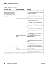
... supply PCA provides the necessary voltages for the electrophotographic processes. If the pins are damaged, replace the high voltage connector assembly. 146 Troubleshooting/Maintenance C4224-90962 If they are not dirty or corroded and that the pins are damaged, replace...(callout 1), drum ground (callout 2), and developing roller (callout 3). Figure 5-5 Toner cartridge high-voltage connection points Checking the high-voltage connector assembly The assembly uses three spring-loaded pins to clean the connections. Use only alcohol to contact the toner cartridge: charging (callout ...
... supply PCA provides the necessary voltages for the electrophotographic processes. If the pins are damaged, replace the high voltage connector assembly. 146 Troubleshooting/Maintenance C4224-90962 If they are not dirty or corroded and that the pins are damaged, replace...(callout 1), drum ground (callout 2), and developing roller (callout 3). Figure 5-5 Toner cartridge high-voltage connection points Checking the high-voltage connector assembly The assembly uses three spring-loaded pins to clean the connections. Use only alcohol to contact the toner cartridge: charging (callout ...

Service Manual
Page 142
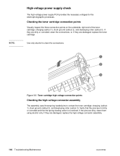
... picked up or is not moving through the paper path, you to relax as the paper cools while resting on a flat surface. Figure 5-6 High-voltage connector assembly Paper curl Paper curl is inherent to the laser printing processes, and occurs when paper is subjected to observe all of the paper motion...
... picked up or is not moving through the paper path, you to relax as the paper cools while resting on a flat surface. Figure 5-6 High-voltage connector assembly Paper curl Paper curl is inherent to the laser printing processes, and occurs when paper is subjected to observe all of the paper motion...
Service Manual
Page 158
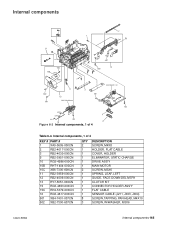
... SCREW, M4X8 HOLDER, FLAT CABLE COVER, HOLDER ELIMINATOR, STATIC CHARGE DRIVE ASS'Y MAIN MOTOR SCREW, M3X6 SPRING, LEAF, LEFT GUIDE, FACE DOWN DELIVERY CLUTCH KIT CONNECTOR HOLDER ASS'Y FLAT CABLE SENSOR CABLE (J211, J003, J004) SCREW, TAPPING, PAN HEAD, M4X10 SCREW, W/WASHER, M3X6 C4224-90962 Internal components 165
... SCREW, M4X8 HOLDER, FLAT CABLE COVER, HOLDER ELIMINATOR, STATIC CHARGE DRIVE ASS'Y MAIN MOTOR SCREW, M3X6 SPRING, LEAF, LEFT GUIDE, FACE DOWN DELIVERY CLUTCH KIT CONNECTOR HOLDER ASS'Y FLAT CABLE SENSOR CABLE (J211, J003, J004) SCREW, TAPPING, PAN HEAD, M4X10 SCREW, W/WASHER, M3X6 C4224-90962 Internal components 165

Service Manual
Page 168
... XB2-7300-607 CN QTY 3 1 1 1 1 1 1 1 1 1 1 1 6 1 1 1 DESCRIPTION SPACER, PCB CASE, PRINTER CONTROLLER SHEET, INSULATING HOLDER, POWER SWITCH LEVER LEVER, POWER SWITCH ROD, SWITCH FLAT CABLE, (J201) CONNECTOR, 2P (J008) DOOR SENSOR ASS'Y MOTOR CABLE,(J007, J401) THERMISTOR CABLE (J008, J206) PLATE, GROUNDING SCREW, M3X6 ECU PCB ASS'Y ECU PCB ASS'Y SCREW, M3X6...
... XB2-7300-607 CN QTY 3 1 1 1 1 1 1 1 1 1 1 1 6 1 1 1 DESCRIPTION SPACER, PCB CASE, PRINTER CONTROLLER SHEET, INSULATING HOLDER, POWER SWITCH LEVER LEVER, POWER SWITCH ROD, SWITCH FLAT CABLE, (J201) CONNECTOR, 2P (J008) DOOR SENSOR ASS'Y MOTOR CABLE,(J007, J401) THERMISTOR CABLE (J008, J206) PLATE, GROUNDING SCREW, M3X6 ECU PCB ASS'Y ECU PCB ASS'Y SCREW, M3X6...
Service Manual
Page 171
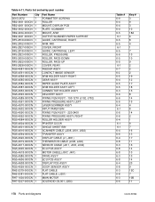
...-DOWN ROLLER, FACE-UP COVER, REAR FEEDER ASS'Y CONTACT IMAGE SENSOR ARM HOLDER ASS'Y RIGHT GEAR ASS'Y PAPER GUIDE PLATE ASS'Y ARM HOLDER ASS'Y LEFT CONNECTOR HOLDER ASS'Y DELIVERY ASS'Y FIXING FILM ASS'Y - 100-127V (J102, J702) FIXING PRESSURE ASS'Y, LEFT LASER/SCANNER ASS'Y INPUT PAPER BIN FIXING FILM ASS'Y - 220...
...-DOWN ROLLER, FACE-UP COVER, REAR FEEDER ASS'Y CONTACT IMAGE SENSOR ARM HOLDER ASS'Y RIGHT GEAR ASS'Y PAPER GUIDE PLATE ASS'Y ARM HOLDER ASS'Y LEFT CONNECTOR HOLDER ASS'Y DELIVERY ASS'Y FIXING FILM ASS'Y - 100-127V (J102, J702) FIXING PRESSURE ASS'Y, LEFT LASER/SCANNER ASS'Y INPUT PAPER BIN FIXING FILM ASS'Y - 220...

Service Manual
Page 172
...-7300-609CN 2 XB6-7300-807 CN 4 Part Name FORMATTER SCREWS SPRING, COMPRESSION SPRING, COMPRESSION CLUTCH KIT GEAR KIT DEVELOPER FASTENER KIT SUBPAD KIT SHIPPING BLOCK CONNECTOR, 2P (J008) TIE, CABLE SCREW, TP, M3X6 SCREW, M4X8 SCREW, M3X6 SCREW, M3X6 SCREW, M4X8 SCREW, M3X6 SCREW, M3X6 SCREW, W/WASHER, M3X6 SCREW, M3X6 SCREW...
...-7300-609CN 2 XB6-7300-807 CN 4 Part Name FORMATTER SCREWS SPRING, COMPRESSION SPRING, COMPRESSION CLUTCH KIT GEAR KIT DEVELOPER FASTENER KIT SUBPAD KIT SHIPPING BLOCK CONNECTOR, 2P (J008) TIE, CABLE SCREW, TP, M3X6 SCREW, M4X8 SCREW, M3X6 SCREW, M3X6 SCREW, M4X8 SCREW, M3X6 SCREW, M3X6 SCREW, W/WASHER, M3X6 SCREW, M3X6 SCREW...


