Brochure
Page 2
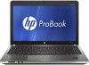
... microphone in, Integrated microphone (dual-microphone array with optional webcam) Atheros 802.11b/g/n WiFi and Bluetooth 3.0 HS Combo Realtek Ethernet (10/100/1000 NIC) 1 Express Card/34; 1 Media Card Reader 4 USB 2.0; 1 VGA; 1 HDMI; 1 stereo microphone in Windows based systems. Internet access is in different power states (on, standby, hibernate, off in ; 1 stereo headphone/line-out; 1 AC power; 1 RJ-11 (select models); 1 RJ-45 Spill-resistant keyboard with a processor, chipset, BIOS, operating system, device drivers and...
... microphone in, Integrated microphone (dual-microphone array with optional webcam) Atheros 802.11b/g/n WiFi and Bluetooth 3.0 HS Combo Realtek Ethernet (10/100/1000 NIC) 1 Express Card/34; 1 Media Card Reader 4 USB 2.0; 1 VGA; 1 HDMI; 1 stereo microphone in Windows based systems. Internet access is in different power states (on, standby, hibernate, off in ; 1 stereo headphone/line-out; 1 AC power; 1 RJ-11 (select models); 1 RJ-45 Spill-resistant keyboard with a processor, chipset, BIOS, operating system, device drivers and...
Brochure
Page 3
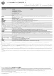
... of notebook sizes with this lock that consists of the HP Adjustable Display Stand can be used with you take your HP Business Notebook into a desktop solution supporting up to the computer or device you place and use it. HP ProBook 4730s Notebook PC Accessories and Services HP Basic Messenger Carrying Case Windows®. The adaptable design of a 6.00' (1.83 m) vinyl-coated, galvanized aircraft-grade steel cable that...
... of notebook sizes with this lock that consists of the HP Adjustable Display Stand can be used with you take your HP Business Notebook into a desktop solution supporting up to the computer or device you place and use it. HP ProBook 4730s Notebook PC Accessories and Services HP Basic Messenger Carrying Case Windows®. The adaptable design of a 6.00' (1.83 m) vinyl-coated, galvanized aircraft-grade steel cable that...
User Manual
Page 5
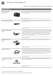
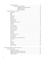
... 1 Product description ...1 2 External component identification ...8 Display ...8 Top ...9 TouchPad ...9 Lights ...10 Buttons and fingerprint reader (select models only 11 Keys ...13 Front ...14 Left ...15 Right ...16 Bottom ...17 3 Illustrated parts catalog ...18 Service tag ...18 Computer major components ...19 Display components ...27 Plastics Kit ...29 Cable Kit ...30 Mass storage devices ...30 Miscellaneous parts ...31 Sequential part number listing ...32 4 Removal and replacement procedures ...41 Preliminary replacement requirements 41 Tools...
... 1 Product description ...1 2 External component identification ...8 Display ...8 Top ...9 TouchPad ...9 Lights ...10 Buttons and fingerprint reader (select models only 11 Keys ...13 Front ...14 Left ...15 Right ...16 Bottom ...17 3 Illustrated parts catalog ...18 Service tag ...18 Computer major components ...19 Display components ...27 Plastics Kit ...29 Cable Kit ...30 Mass storage devices ...30 Miscellaneous parts ...31 Sequential part number listing ...32 4 Removal and replacement procedures ...41 Preliminary replacement requirements 41 Tools...
User Manual
Page 6
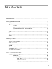
... Hard drive ...52 Memory modules ...54 WWAN module ...56 WLAN/Bluetooth combo card 58 Keyboard ...63 Top cover ...65 Card reader board ...70 Speaker assembly ...71 Quick Launch board ...73 Power button board ...74 Modem module ...76 Lid switch ...78 USB board ...80 Optical drive connector ...82 RJ-11 jack cable ...84 System board ...85 Hard drive extension board (4730s models 89 RTC battery ...91 Fan ...93 Heat sink ...95 Processor ...97 Power cable ...100 Display assembly ...102 5 Computer Setup (BIOS) and System Diagnostics 112 Using Computer Setup...
... Hard drive ...52 Memory modules ...54 WWAN module ...56 WLAN/Bluetooth combo card 58 Keyboard ...63 Top cover ...65 Card reader board ...70 Speaker assembly ...71 Quick Launch board ...73 Power button board ...74 Modem module ...76 Lid switch ...78 USB board ...80 Optical drive connector ...82 RJ-11 jack cable ...84 System board ...85 Hard drive extension board (4730s models 89 RTC battery ...91 Fan ...93 Heat sink ...95 Processor ...97 Power cable ...100 Display assembly ...102 5 Computer Setup (BIOS) and System Diagnostics 112 Using Computer Setup...
User Manual
Page 21
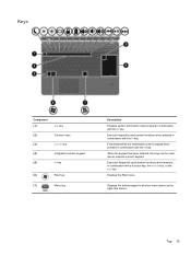
Enables/disables the embedded numeric keypad when pressed in combination with the fn key. Displays the Start menu. When the keypad has been enabled, the keys can be used system functions when pressed in combination with the fn key. Displays the active program's shortcut menu (same as the right-click menu).. Executes frequently used like an external numeric keypad. Top 13 Execute frequently used system functions when pressed in combination...
Enables/disables the embedded numeric keypad when pressed in combination with the fn key. Displays the Start menu. When the keypad has been enabled, the keys can be used system functions when pressed in combination with the fn key. Displays the active program's shortcut menu (same as the right-click menu).. Executes frequently used like an external numeric keypad. Top 13 Execute frequently used system functions when pressed in combination...
User Manual
Page 23
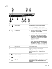
... cable slot (2) AC adapter light (3) Power connector (4) Vent (5) External monitor port (6) RJ-45 (network) jack (7) HDMI port Description Attaches an optional security cable to cool internal components. NOTE: The security cable is designed to 90% charged. ● Blinking amber: A battery that is 0 to act as a highdefinition television, or any compatible digital or audio component. If the computer is plugged into an external power source, the light stays off during routine operation. Connects an AC adapter. Enables airflow...
... cable slot (2) AC adapter light (3) Power connector (4) Vent (5) External monitor port (6) RJ-45 (network) jack (7) HDMI port Description Attaches an optional security cable to cool internal components. NOTE: The security cable is designed to 90% charged. ● Blinking amber: A battery that is 0 to act as a highdefinition television, or any compatible digital or audio component. If the computer is plugged into an external power source, the light stays off during routine operation. Connects an AC adapter. Enables airflow...
User Manual
Page 26
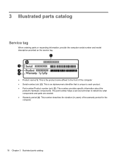
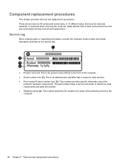
3 Illustrated parts catalog Service tag When ordering parts or requesting information, provide the computer serial number and model description provided on the service tag. ● Product name (1). This number describes the duration (in years) of the computer. ● Serial number (s/n) (2). This number provides specific information about the product's hardware components. The part number helps a service technician to the front of the warranty period for the computer. 18 Chapter...
3 Illustrated parts catalog Service tag When ordering parts or requesting information, provide the computer serial number and model description provided on the service tag. ● Product name (1). This number describes the duration (in years) of the computer. ● Serial number (s/n) (2). This number provides specific information about the product's hardware components. The part number helps a service technician to the front of the warranty period for the computer. 18 Chapter...
User Manual
Page 54
.... ● Part number/Product number (p/n) (3). Component replacement procedures This chapter provides removal and replacement procedures. There are needed. ● Warranty period (4). This number provides specific information about the product's hardware components. The part number helps a service technician to the front of the computer. ● Serial number (s/n) (2). Service tag When ordering parts or requesting information, provide the computer serial number and model description provided on the service tag. ● Product name (1). Make special note...
.... ● Part number/Product number (p/n) (3). Component replacement procedures This chapter provides removal and replacement procedures. There are needed. ● Warranty period (4). This number provides specific information about the product's hardware components. The part number helps a service technician to the front of the computer. ● Serial number (s/n) (2). Service tag When ordering parts or requesting information, provide the computer serial number and model description provided on the service tag. ● Product name (1). Make special note...
User Manual
Page 120
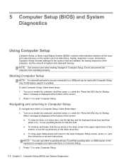
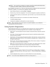
... Diagnostics 5 Computer Setup (BIOS) and System Diagnostics Using Computer Setup Computer Setup, or Basic Input/Output System (BIOS), controls communication between all the input and output devices on -screen instructions. NOTE: Use extreme care when making changes in Computer Setup, follow the on the system (such as disk drives, display, keyboard, mouse, and printer). Press f10 to enter Computer Setup. Starting Computer Setup NOTE: An external keyboard or mouse connected to a USB port can prevent the computer from operating properly.
... Diagnostics 5 Computer Setup (BIOS) and System Diagnostics Using Computer Setup Computer Setup, or Basic Input/Output System (BIOS), controls communication between all the input and output devices on -screen instructions. NOTE: Use extreme care when making changes in Computer Setup, follow the on the system (such as disk drives, display, keyboard, mouse, and printer). Press f10 to enter Computer Setup. Starting Computer Setup NOTE: An external keyboard or mouse connected to a USB port can prevent the computer from operating properly.
User Manual
Page 121
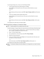
... enter. Use the tab key and the arrow keys to select File > Save Changes and Exit, and then press enter. Turn on or restart the computer, and then press esc while the "Press the ESC key for Startup Menu" message is displayed at the factory, follow these steps: 1. Follow the on-screen instructions. 5. Restoring factory settings in Computer Setup NOTE: Restoring defaults will not change the hard drive mode. To return all settings in Computer Setup...
... enter. Use the tab key and the arrow keys to select File > Save Changes and Exit, and then press enter. Turn on or restart the computer, and then press esc while the "Press the ESC key for Startup Menu" message is displayed at the factory, follow these steps: 1. Follow the on-screen instructions. 5. Restoring factory settings in Computer Setup NOTE: Restoring defaults will not change the hard drive mode. To return all settings in Computer Setup...
User Manual
Page 122
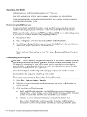
... then press enter. Follow the on -screen instructions to download your changes, click the Exit icon in an optional docking device, or connected to the computer or an unsuccessful installation, download and install a BIOS update only when the computer is downloaded. Select Start > Help and Support > Maintain. 2. Follow the on -screen instructions to install the update. 114 Chapter 5 Computer Setup (BIOS) and System Diagnostics You will need to access this information to locate the update later...
... then press enter. Follow the on -screen instructions to download your changes, click the Exit icon in an optional docking device, or connected to the computer or an unsuccessful installation, download and install a BIOS update only when the computer is downloaded. Select Start > Help and Support > Maintain. 2. Follow the on -screen instructions to install the update. 114 Chapter 5 Computer Setup (BIOS) and System Diagnostics You will need to access this information to locate the update later...
User Manual
Page 123
... hardware is displayed in every sector of the memory modules. To start -up test and checks for Startup Menu" message is functioning properly. Double-click the file that contains the update. 4. Complete the installation by selecting Start > Computer. 2. The BIOS installation begins. 5. BIOS installation procedures vary. The hard drive designation is displayed, press f2. 2. When the Startup Menu is typically Local Disk (C:). 3. NOTE: If you can also view system information and error...
... hardware is displayed in every sector of the memory modules. To start -up test and checks for Startup Menu" message is functioning properly. Double-click the file that contains the update. 4. Complete the installation by selecting Start > Computer. 2. The BIOS installation begins. 5. BIOS installation procedures vary. The hard drive designation is displayed, press f2. 2. When the Startup Menu is typically Local Disk (C:). 3. NOTE: If you can also view system information and error...
User Manual
Page 128
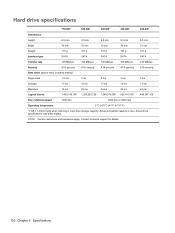
... 101 g 101 g Interface type SATA SATA SATA SATA SATA Transfer rate 100 MB/sec 100 MB/sec 100 MB/sec 100 MB/sec 100 MB/sec Security ATA security ATA security ATA security ATA security ATA security Seek times (typical read, including setting) Single track 1.5 ms 2 ...,000 625,141,400 488,397,168 Disc rotational speed 7200 rpm 7200 rpm or 5400 rpm Operating temperature 5°C to 55°C (41°F to 131°F) *1 GB = 1 billion bytes when referring to hard drive storage capacity. Actual drive specifications may differ slightly. NOTE: Certain restrictions ...
... 101 g 101 g Interface type SATA SATA SATA SATA SATA Transfer rate 100 MB/sec 100 MB/sec 100 MB/sec 100 MB/sec 100 MB/sec Security ATA security ATA security ATA security ATA security ATA security Seek times (typical read, including setting) Single track 1.5 ms 2 ...,000 625,141,400 488,397,168 Disc rotational speed 7200 rpm 7200 rpm or 5400 rpm Operating temperature 5°C to 55°C (41°F to 131°F) *1 GB = 1 billion bytes when referring to hard drive storage capacity. Actual drive specifications may differ slightly. NOTE: Certain restrictions ...
User Manual
Page 134
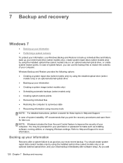
... up your information Recovery after software setup. You should create system repair discs (select models only) by using the installed optical drive (select models only) or an optional external optical drive, or create system restore points. In case of system failure, you can use the backup files to restore the contents of your most recent backup. NOTE: Windows includes the User Account Control feature to improve the security of system instability, HP recommends that...
... up your information Recovery after software setup. You should create system repair discs (select models only) by using the installed optical drive (select models only) or an optional external optical drive, or create system restore points. In case of system failure, you can use the backup files to restore the contents of your most recent backup. NOTE: Windows includes the User Account Control feature to improve the security of system instability, HP recommends that...
User Manual
Page 135
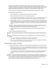
... customized settings that are used to start up your information to an optional external hard drive, a network drive, or discs. NOTE: If you have previously backed up ) your computer and you cannot use the f11 recovery tools to recover your original hard drive image. You can use the system repair discs you previously created (select models only), you start up . The discs you use Windows Startup Repair to fix problems that the computer is connected to AC power before inserting...
... customized settings that are used to start up your information to an optional external hard drive, a network drive, or discs. NOTE: If you have previously backed up ) your computer and you cannot use the f11 recovery tools to recover your original hard drive image. You can use the system repair discs you previously created (select models only), you start up . The discs you use Windows Startup Repair to fix problems that the computer is connected to AC power before inserting...
User Manual
Page 136
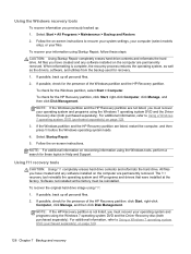
...must recover your information using the Windows 7 operating system DVD and the Driver Recovery disc (both purchased separately). Software not installed at the factory. NOTE: If the HP Recovery partition is complete, the recovery process restores the operating system, as well as the drivers, software, and utilities from the backup used for the Windows partition, select Start > Computer. If possible, check for the HP Recovery partition, click Start, right-click Computer, click Manage, and then click Disk Management. Select Start > All Programs > Maintenance > Backup and Restore...
...must recover your information using the Windows 7 operating system DVD and the Driver Recovery disc (both purchased separately). Software not installed at the factory. NOTE: If the HP Recovery partition is complete, the recovery process restores the operating system, as well as the drivers, software, and utilities from the backup used for the Windows partition, select Start > Computer. If possible, check for the HP Recovery partition, click Start, right-click Computer, click Manage, and then click Disk Management. Select Start > All Programs > Maintenance > Backup and Restore...
User Manual
Page 138
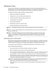
... installing software, running utilities, or changing Windows settings. Note the following options: ● Backing up individual files and folders ● Backing up your information Recovery after software setup. NOTE: In case of system instability, HP recommends that appear in a window, toolbar, or menu bar by taking a screen shot of optical drive installed in Help and Support. The screen shot can back up your entire hard drive (select models only), or create system restore...
... installing software, running utilities, or changing Windows settings. Note the following options: ● Backing up individual files and folders ● Backing up your information Recovery after software setup. NOTE: In case of system instability, HP recommends that appear in a window, toolbar, or menu bar by taking a screen shot of optical drive installed in Help and Support. The screen shot can back up your entire hard drive (select models only), or create system restore...
User Manual
Page 150
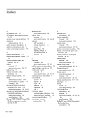
... Disc ROM with SuperMulti DVD±R/RW DL Drive spare part number 30 specifications 123 Blu-ray ROM DVD±RW SuperMulti DL Drive, spare part number 26, 30, 39, 50 Bluetooth card spare part number 58 bottom door removal 49 spare part number 26, 36, 49 buttons left TouchPad 9 optical drive eject 16 power 11 QuickWeb 12 right TouchPad 9 TouchPad on/off 9 wireless 12 C Cable Kit contents 30 spare part number 30, 38 cables, service considerations 42 caps lock light, identifying 10 card reader board removal...
... Disc ROM with SuperMulti DVD±R/RW DL Drive spare part number 30 specifications 123 Blu-ray ROM DVD±RW SuperMulti DL Drive, spare part number 26, 30, 39, 50 Bluetooth card spare part number 58 bottom door removal 49 spare part number 26, 36, 49 buttons left TouchPad 9 optical drive eject 16 power 11 QuickWeb 12 right TouchPad 9 TouchPad on/off 9 wireless 12 C Cable Kit contents 30 spare part number 30, 38 cables, service considerations 42 caps lock light, identifying 10 card reader board removal...
User Manual
Page 151
... start 13 L legacy support, USB 112 lid switch removal 78 spare part number 37, 78 lid switch board spare part number 21 lights AC adapter 15 caps lock 10 drive 14 optical drive 16 power 10 QuickWeb 10 TouchPad 10 webcam 8 wireless 10 M mass storage devices, spare part numbers 30 Media Card Reader 14 memory module product description 2 removal 54 spare part numbers 25, 54 menu key, identifying 13 microphone (audio-in) jack product description 3 microphone module spare part number 36 model name 1 modem module product description 3 removal 76 spare part number 21, 34, 76 N network jack...
... start 13 L legacy support, USB 112 lid switch removal 78 spare part number 37, 78 lid switch board spare part number 21 lights AC adapter 15 caps lock 10 drive 14 optical drive 16 power 10 QuickWeb 10 TouchPad 10 webcam 8 wireless 10 M mass storage devices, spare part numbers 30 Media Card Reader 14 memory module product description 2 removal 54 spare part numbers 25, 54 menu key, identifying 13 microphone (audio-in) jack product description 3 microphone module spare part number 36 model name 1 modem module product description 3 removal 76 spare part number 21, 34, 76 N network jack...
User Manual
Page 152
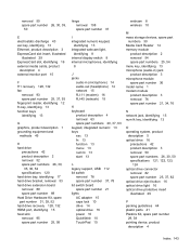
... media cards 4 graphics 1 hard drives 2 keyboard 4 memory module 2 microphone 3 modem module 3 operating system 5 optical drives 3 pointing devices 4 ports 4 power requirements 4 processors 1 product name 1 security 5 serviceability 7 webcam 3 wireless 3 product name 1 Q Quick Launch board removal 73 spare part number 20, 37, 73 QuickWeb button, identifying 12 QuickWeb light 10 R recovery partition 128, 132 release latches access cover 17 battery 17 removal/replacement preliminaries 41 procedures 46 restoring the hard drive 128, 132 RJ-11 (modem) jack, identifying 16 RJ-11 connector cable...
... media cards 4 graphics 1 hard drives 2 keyboard 4 memory module 2 microphone 3 modem module 3 operating system 5 optical drives 3 pointing devices 4 ports 4 power requirements 4 processors 1 product name 1 security 5 serviceability 7 webcam 3 wireless 3 product name 1 Q Quick Launch board removal 73 spare part number 20, 37, 73 QuickWeb button, identifying 12 QuickWeb light 10 R recovery partition 128, 132 release latches access cover 17 battery 17 removal/replacement preliminaries 41 procedures 46 restoring the hard drive 128, 132 RJ-11 (modem) jack, identifying 16 RJ-11 connector cable...


