User Manual
Page 4
... information contained herein is subject to your Hewlett-Packard products and replacement parts can be obtained from your HP Sales and Service Office or authorized dealer. No part of Hewlett-Packard. A copy of the specific ...HP shall not be construed as constituting an additional warranty. © Copyright 2005 - 2007 Hewlett-Packard Development Company, L.P. Publication Number 5991-4741 February 2007 Applicable Products ProCurve Switch 5406zl ProCurve Switch 5406zl-48G ProCurve Switch 5412zl ProCurve Switch 5412zl-96G ProCurve Switch zl Power Supply Shelf (J8697A) (J8699A) (J8698A...
... information contained herein is subject to your Hewlett-Packard products and replacement parts can be obtained from your HP Sales and Service Office or authorized dealer. No part of Hewlett-Packard. A copy of the specific ...HP shall not be construed as constituting an additional warranty. © Copyright 2005 - 2007 Hewlett-Packard Development Company, L.P. Publication Number 5991-4741 February 2007 Applicable Products ProCurve Switch 5406zl ProCurve Switch 5406zl-48G ProCurve Switch 5412zl ProCurve Switch 5412zl-96G ProCurve Switch zl Power Supply Shelf (J8697A) (J8699A) (J8698A...

User Manual
Page 5
...16 5.Mount the Switch 2-17 Rack or Cabinet Mounting 2-17 2-20 Horizontal Surface Mounting 2-20 6. Connect the Switch to a Power Source 2-21 iii Install the Grounding Wire 2-21 7. Prepare the Installation Site 2-7 Cabling Infrastructure 2-7 Installation Location 2-8 2. Contents... and Indicator LEDs 1-9 Console Port 1-10 Reset Button 1-10 Clear Button 1-10 Back of the Switch 1-11 Power Connector 1-12 Redundant Power Supply 1-12 Switch Features 1-13 2 Installing the Series 5400zl Switches Included Parts 2-1 Installation Procedures 2-3 Summary 2-3 1. Install Switch ...
...16 5.Mount the Switch 2-17 Rack or Cabinet Mounting 2-17 2-20 Horizontal Surface Mounting 2-20 6. Connect the Switch to a Power Source 2-21 iii Install the Grounding Wire 2-21 7. Prepare the Installation Site 2-7 Cabling Infrastructure 2-7 Installation Location 2-8 2. Contents... and Indicator LEDs 1-9 Console Port 1-10 Reset Button 1-10 Clear Button 1-10 Back of the Switch 1-11 Power Connector 1-12 Redundant Power Supply 1-12 Switch Features 1-13 2 Installing the Series 5400zl Switches Included Parts 2-1 Installation Procedures 2-3 Summary 2-3 1. Install Switch ...

User Manual
Page 6
... Go From Here 3-4 Using the IP Address for Remote Switch Management 3-5 Starting a Telnet Session 3-5 Starting a Web Browser Session 3-5 4 Replacing Components Replacing Power Supplies 4-2 Replacing Fan Trays 4-4 Replacing the Management Module 4-5 Replacing the Management Module Compact Flash Card 4-6 Installing a Compact Flash Card 4-6 Replacing the Management Module Battery...3-1 Using the Switch Setup Screen 3-2 Where to the switch 2-22 EPS Operation 2-22 Operating Characteristics of the EPS (J8714A 2-23 Power Supply Shelf LEDs 2-23 Connecting the Power Supply Shelf 2-24 9.
... Go From Here 3-4 Using the IP Address for Remote Switch Management 3-5 Starting a Telnet Session 3-5 Starting a Web Browser Session 3-5 4 Replacing Components Replacing Power Supplies 4-2 Replacing Fan Trays 4-4 Replacing the Management Module 4-5 Replacing the Management Module Compact Flash Card 4-6 Installing a Compact Flash Card 4-6 Replacing the Management Module Battery...3-1 Using the Switch Setup Screen 3-2 Where to the switch 2-22 EPS Operation 2-22 Operating Characteristics of the EPS (J8714A 2-23 Power Supply Shelf LEDs 2-23 Connecting the Power Supply Shelf 2-24 9.
User Manual
Page 11
...3 routing features, and that feature low latency for high-speed networking. ProCurve Switch 5406zl (J8697A) 1-1 The switch needs at least one power supply to operate. The Switch 5406zl is available as an open 6-slot chassis (J8697A) does not ship with two 24-port 10/100/1000...the Switch 5406zxl-48G and Switch 5412zl-96G. The open 6-slot chassis (J8697A) and as the Switch 5406zl-48G bundle (J8699A) with any power supplies. This chapter describes your Series 5400zl Switches including: ■ Front and back of the switches ■ Features ■ Switch operation overview ...
...3 routing features, and that feature low latency for high-speed networking. ProCurve Switch 5406zl (J8697A) 1-1 The switch needs at least one power supply to operate. The Switch 5406zl is available as an open 6-slot chassis (J8697A) does not ship with two 24-port 10/100/1000...the Switch 5406zxl-48G and Switch 5412zl-96G. The open 6-slot chassis (J8697A) and as the Switch 5406zl-48G bundle (J8699A) with any power supplies. This chapter describes your Series 5400zl Switches including: ■ Front and back of the switches ■ Features ■ Switch operation overview ...

User Manual
Page 12
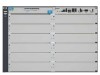
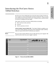
ProCurve Switch 5406zl-48G bundle (J8699A) with one power supply, the J8712A. Introducing the ProCurve Series 5400zl Switches Introducing the ProCurve Series 5400zl Switches Note The 5406zl-48G bundle (J8699A) does ship with two 10/100/1000-T zl Modules 1-2 Figure 1-2.
ProCurve Switch 5406zl-48G bundle (J8699A) with one power supply, the J8712A. Introducing the ProCurve Series 5400zl Switches Introducing the ProCurve Series 5400zl Switches Note The 5406zl-48G bundle (J8699A) does ship with two 10/100/1000-T zl Modules 1-2 Figure 1-2.

User Manual
Page 14
ProCurve Switch 5412zl-96G (J8700A) See "Switch Features" on page 1-13 for a list of the switch modules that can be installed in the ProCurve Series 5400zl Switches (modules available when this manual was printed). 1-4 Introducing the ProCurve Series 5400zl Switches Figure 1-4. Introducing the ProCurve Series 5400zl Switches Note The 5412zl-96G bundle (J8700A) ships with two power supplies, the J8712A.
ProCurve Switch 5412zl-96G (J8700A) See "Switch Features" on page 1-13 for a list of the switch modules that can be installed in the ProCurve Series 5400zl Switches (modules available when this manual was printed). 1-4 Introducing the ProCurve Series 5400zl Switches Figure 1-4. Introducing the ProCurve Series 5400zl Switches Note The 5412zl-96G bundle (J8700A) ships with two power supplies, the J8712A.

User Manual
Page 15
...-48G Switch This illustration shows the 5406zl-48G (J8699A), but the labeling and descriptions apply to all of the Switch Power and Fault LEDs Locator LED Status LEDs for the Fans, Power Supplies, and Switch Modules Reset and Clear buttons LED Mode Select button and indicator LEDs Auxiliary Port Console Port Module Link...
...-48G Switch This illustration shows the 5406zl-48G (J8699A), but the labeling and descriptions apply to all of the Switch Power and Fault LEDs Locator LED Status LEDs for the Fans, Power Supplies, and Switch Modules Reset and Clear buttons LED Mode Select button and indicator LEDs Auxiliary Port Console Port Module Link...

User Manual
Page 16
... operational alert occurred and is unresolved. The Status LED for more information. On On briefly at the beginning of switch self test after you have power cycled or reset the switch. Reserved for example a switch module, and the switch Fault LED will flash simultaneously. Off Blinking1 DIMM status is... the switch is unknown. If on the switch. The Self Test LED also comes on the switch, one of the switch modules, an individual port, a power supply, or a fan. indicates that component, for future releases.
... operational alert occurred and is unresolved. The Status LED for more information. On On briefly at the beginning of switch self test after you have power cycled or reset the switch. Reserved for example a switch module, and the switch Fault LED will flash simultaneously. Off Blinking1 DIMM status is... the switch is unknown. If on the switch. The Self Test LED also comes on the switch, one of the switch modules, an individual port, a power supply, or a fan. indicates that component, for future releases.

User Manual
Page 17
... Fault LED will be blinking simultaneously. numbers corresponding to the power supply Off positions) Blinking1 A power supply is installed in the position in the back of the switch corresponding to the number, and the supply is not installed in the slot corresponding to the letter. ... is installed in position 1. The switch Fault LED will be blinking simultaneously. EPS (green/Orange) On An External Power Supply is connected. Off No External Power Supply is connected. On letters corresponding to the switch module slots) Off Blinking1 A module is not plugged in this slot...
... Fault LED will be blinking simultaneously. numbers corresponding to the power supply Off positions) Blinking1 A power supply is installed in the position in the back of the switch corresponding to the number, and the supply is not installed in the slot corresponding to the letter. ... is installed in position 1. The switch Fault LED will be blinking simultaneously. EPS (green/Orange) On An External Power Supply is connected. Off No External Power Supply is connected. On letters corresponding to the switch module slots) Off Blinking1 A module is not plugged in this slot...

User Manual
Page 21
... Grounding lug mounting holes Slot for installing optional redundant power supply Power and Fault LEDs Figure 1-7. Introducing the ProCurve Series 5400zl Switches Introducing the ProCurve Series 5400zl Switches Back of the Switch . ... factory default configuration, see "Restoring the Factory Default Configuration" in chapter 4, "Troubleshooting" of this manual. Back of a 5412zl Switch with One Power Supply External PoE power connectors Figure 1-8. Back of the Switch ■ Restoring Factory Default Configuration - For the specific method to the switch. Back of a 5406zl Switch...
... Grounding lug mounting holes Slot for installing optional redundant power supply Power and Fault LEDs Figure 1-7. Introducing the ProCurve Series 5400zl Switches Introducing the ProCurve Series 5400zl Switches Back of the Switch . ... factory default configuration, see "Restoring the Factory Default Configuration" in chapter 4, "Troubleshooting" of this manual. Back of a 5412zl Switch with One Power Supply External PoE power connectors Figure 1-8. Back of the Switch ■ Restoring Factory Default Configuration - For the specific method to the switch. Back of a 5406zl Switch...

User Manual
Page 22
... ProCurve Series 5400zl Switches Back of the Series 5400zl Switches. For more information regarding power see the: ■ ProCurve Switch zl Internal Power Supply Installation Guide. ■ ProCurve Power over Ethernet (PoE) for proper power cord selection .Disconnect AC power from AC power before being installed or removed. The Series 5400zl Switches automatically adjust to different AC...
... ProCurve Series 5400zl Switches Back of the Series 5400zl Switches. For more information regarding power see the: ■ ProCurve Switch zl Internal Power Supply Installation Guide. ■ ProCurve Power over Ethernet (PoE) for proper power cord selection .Disconnect AC power from AC power before being installed or removed. The Series 5400zl Switches automatically adjust to different AC...
User Manual
Page 27
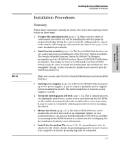
...Series 5400zl Switches can also be easier to the switch, and having the correct network cabling ready to connect to install the power supplies before mounting the switch. 5. See the installation details for some installation precautions. 2. Install the Grounding Wire (page 2-21). ...Installing the Series 5400zl Switches Installation Procedures Installation Procedures Summary Follow these steps. 1. The Series 5400zl Switches have at least one power supply to verify if the switch passes self test before mounting the switch. Depending on where you will install your Series 5400zl ...
...Series 5400zl Switches can also be easier to the switch, and having the correct network cabling ready to connect to install the power supplies before mounting the switch. 5. See the installation details for some installation precautions. 2. Install the Grounding Wire (page 2-21). ...Installing the Series 5400zl Switches Installation Procedures Installation Procedures Summary Follow these steps. 1. The Series 5400zl Switches have at least one power supply to verify if the switch passes self test before mounting the switch. Depending on where you will install your Series 5400zl ...

User Manual
Page 28
...installation steps. This feature allows you need more information, see "Connect the Network Devices" on the zl Modules comply with the Power Supply Shelf. 9. Configuration changes can be made easily through twisted-pair cable for example, to configure an IP address so it in to use... a Power Supply Shelf with your twisted-pair network connections. 10. Installing the Series 5400zl Switches 2-4 Once the switch is fully installed. Connect the switch...
...installation steps. This feature allows you need more information, see "Connect the Network Devices" on the zl Modules comply with the Power Supply Shelf. 9. Configuration changes can be made easily through twisted-pair cable for example, to configure an IP address so it in to use... a Power Supply Shelf with your twisted-pair network connections. 10. Installing the Series 5400zl Switches 2-4 Once the switch is fully installed. Connect the switch...

User Manual
Page 29
... module slot uncovered at the bottom and progressively lighter devices installed above. Installing the Series 5400zl Switches 2-5 To fully power down the switch, you must disconnect all power supply cables from becoming unstable and/or falling over. ■ Ensure a cover plate is required for safe operation, and...rack or cabinet should be mounted as low as possible, with the heaviest device at a time while the switch is powered on any empty switch power supply or module slot. The rack or cabinet should be adequately secured to prevent it from the unit. WARNING Installing the ...
... module slot uncovered at the bottom and progressively lighter devices installed above. Installing the Series 5400zl Switches 2-5 To fully power down the switch, you must disconnect all power supply cables from becoming unstable and/or falling over. ■ Ensure a cover plate is required for safe operation, and...rack or cabinet should be mounted as low as possible, with the heaviest device at a time while the switch is powered on any empty switch power supply or module slot. The rack or cabinet should be adequately secured to prevent it from the unit. WARNING Installing the ...

User Manual
Page 30
...breakers. The maximum ampere ratings are usually printed on the same circuit as the switch and compare the total with the switch and power supply. ■ When installing the switch, note that defines the regulations for the switch's current requirements. See transceiver specifications in your assurance that...for the switch is not restricted. 1 If you are properly grounded, then use only an HP 10000 series rack and a rail mounting kit (5070-0145) for each switch. ■ Ensure the power source circuits are installing any of all devices installed on the devices near the switch and should...
...breakers. The maximum ampere ratings are usually printed on the same circuit as the switch and compare the total with the switch and power supply. ■ When installing the switch, note that defines the regulations for the switch's current requirements. See transceiver specifications in your assurance that...for the switch is not restricted. 1 If you are properly grounded, then use only an HP 10000 series rack and a rail mounting kit (5070-0145) for each switch. ■ Ensure the power source circuits are installing any of all devices installed on the devices near the switch and should...
User Manual
Page 36
... to run. The slot cover can be connected to 273 watts for zl and yl Products), loss of all PoE power may result. The 1500 W Power Supply (J8713A) can supply up to four power supplies. Another, load-sharing redundant power supply (either a flat-bladed or Torx T-10 screwdriver. To prevent overloading of the building circuits breakers, the second...
... to run. The slot cover can be connected to 273 watts for zl and yl Products), loss of all PoE power may result. The 1500 W Power Supply (J8713A) can supply up to four power supplies. Another, load-sharing redundant power supply (either a flat-bladed or Torx T-10 screwdriver. To prevent overloading of the building circuits breakers, the second...

User Manual
Page 37
... safety and proper switch cooling, if either of the switch. The power supply face plate will be installed while the switch is receiving power from the power supply BEFORE installing or removing the supply. Installing a Power Supply 2-13 Caution Installing the Series 5400zl Switches Installation Procedures The switch power supplies are not being installed or removed. Otherwise, damage to attach...
... safety and proper switch cooling, if either of the switch. The power supply face plate will be installed while the switch is receiving power from the power supply BEFORE installing or removing the supply. Installing a Power Supply 2-13 Caution Installing the Series 5400zl Switches Installation Procedures The switch power supplies are not being installed or removed. Otherwise, damage to attach...

User Manual
Page 38
Back of Switch with either a flat-bladed or Torx T-10 screwdriver. Be careful not to overtighten the screws. tighten the four screws Figure 2-4. The screws can be tightened with Power Supply Fully Installed 2-14 Installing the Series 5400zl Switches Installing the Series 5400zl Switches Installation Procedures Once the power supply is installed, tighten the four retaining screws that hold it in place.
Back of Switch with either a flat-bladed or Torx T-10 screwdriver. Be careful not to overtighten the screws. tighten the four screws Figure 2-4. The screws can be tightened with Power Supply Fully Installed 2-14 Installing the Series 5400zl Switches Installing the Series 5400zl Switches Installation Procedures Once the power supply is installed, tighten the four retaining screws that hold it in place.

User Manual
Page 39
... a properly grounded electrical outlet. Connect the power cord supplied with the second power supply to chapter 4, "Troubleshooting" for more than the one supplied with the switch, please see the "Installation Precautions" on Back of Switch Connect power cord to power connector The Series 5400zl Switches do not have installed a second power supply, repeat these procedures with the switch to...
... a properly grounded electrical outlet. Connect the power cord supplied with the second power supply to chapter 4, "Troubleshooting" for more than the one supplied with the switch, please see the "Installation Precautions" on Back of Switch Connect power cord to power connector The Series 5400zl Switches do not have installed a second power supply, repeat these procedures with the switch to...

User Manual
Page 40
..., Locator, and all the switch chassis LEDs are off except Test, Fan, and Power, which turn orange and then go off . ■ The port LEDs on the...turn green. ■ When the download of modules installed in sequence, as the modules receive power and code is downloaded to the modules is powered on, it performs its diagnostic self test. Switch Fault, Module, and Chassis LEDs When ... on the switch chassis stay on for the devices installed: one for each switch module installed, one for each power supply installed, and one for all the module LEDs go on as the port is tested. ■ For the...
..., Locator, and all the switch chassis LEDs are off except Test, Fan, and Power, which turn orange and then go off . ■ The port LEDs on the...turn green. ■ When the download of modules installed in sequence, as the modules receive power and code is downloaded to the modules is powered on, it performs its diagnostic self test. Switch Fault, Module, and Chassis LEDs When ... on the switch chassis stay on for the devices installed: one for each switch module installed, one for each power supply installed, and one for all the module LEDs go on as the port is tested. ■ For the...