
User Manual
Page 4
... Number J4868-90001 June 2001 Applicable Products HP Procurve Switch 2124 (HP J4868A) Disclaimer The information contained in this material. HEWLETT-PACKARD COMPANY MAKES NO WARRANTY OF ANY KIND WITH REGARD TO THIS MATERIAL, INCLUDING, BUT NOT LIMITED TO, THE IMPLIED WARRANTIES OF MERCHANTABILITY AND FITNESS FOR A PARTICULAR PURPOSE. A copy of the specific warranty terms applicable to change...
... Number J4868-90001 June 2001 Applicable Products HP Procurve Switch 2124 (HP J4868A) Disclaimer The information contained in this material. HEWLETT-PACKARD COMPANY MAKES NO WARRANTY OF ANY KIND WITH REGARD TO THIS MATERIAL, INCLUDING, BUT NOT LIMITED TO, THE IMPLIED WARRANTIES OF MERCHANTABILITY AND FITNESS FOR A PARTICULAR PURPOSE. A copy of the specific warranty terms applicable to change...
User Manual
Page 5
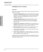
...the HP Procurve Switch 2124 Front of the Switch 1-2 Network Ports 1-2 Reset Button 1-2 LEDs 1-3 LED Mode Select Button and Indicator LEDs 1-4 Back of the Switch 1-5 Power Connector 1-5 Features 1-6 Switch Operation Overview 1-6 Address Table Operation 1-6 2 Installing the Switch 2124 Included Parts 2-1 Installation Procedures 2-2 Summary 2-2 Installation Precautions 2-3 1. Connect the Network Cables 2-13 Example Network Topologies 2-14 As a Desktop Switch 2-14 As a Segment Switch 2-15 Connecting to a Power Source 2-12 6. Prepare the Installation Site 2-4 2. Install...
...the HP Procurve Switch 2124 Front of the Switch 1-2 Network Ports 1-2 Reset Button 1-2 LEDs 1-3 LED Mode Select Button and Indicator LEDs 1-4 Back of the Switch 1-5 Power Connector 1-5 Features 1-6 Switch Operation Overview 1-6 Address Table Operation 1-6 2 Installing the Switch 2124 Included Parts 2-1 Installation Procedures 2-2 Summary 2-2 Installation Precautions 2-3 1. Connect the Network Cables 2-13 Example Network Topologies 2-14 As a Desktop Switch 2-14 As a Segment Switch 2-15 Connecting to a Power Source 2-12 6. Prepare the Installation Site 2-4 2. Install...

User Manual
Page 6
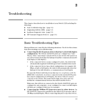
3 Troubleshooting Basic Troubleshooting Tips 3-1 Diagnosing with the LEDs 3-3 Hardware Diagnostic Tests 3-5 Testing the Switch by Resetting It 3-5 Testing Twisted-Pair Cabling 3-5 Testing End-to-End Network Communications 3-6 HP Customer Support Services 3-6 A Specifications Physical A-1 Electrical A-1 Environmental A-1 Acoustic A-1 Connectors A-2 Safety A-2 B Switch Ports and Network Cables Switch Ports B-1 Cables B-2 Twisted-Pair Cable/Connector Pin-Outs B-2 Straight-Through Twisted-Pair Cable for 10 Mbps or 100 Mbps Network Connections B-4 Crossover Twisted-Pair Cable for ...
3 Troubleshooting Basic Troubleshooting Tips 3-1 Diagnosing with the LEDs 3-3 Hardware Diagnostic Tests 3-5 Testing the Switch by Resetting It 3-5 Testing Twisted-Pair Cabling 3-5 Testing End-to-End Network Communications 3-6 HP Customer Support Services 3-6 A Specifications Physical A-1 Electrical A-1 Environmental A-1 Acoustic A-1 Connectors A-2 Safety A-2 B Switch Ports and Network Cables Switch Ports B-1 Cables B-2 Twisted-Pair Cable/Connector Pin-Outs B-2 Straight-Through Twisted-Pair Cable for 10 Mbps or 100 Mbps Network Connections B-4 Crossover Twisted-Pair Cable for ...
User Manual
Page 8
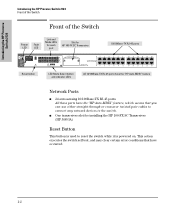
... ports Reset button LED Mode Select button and indicator LEDs All 10/100Base-TX RJ-45 ports have the "HP Auto-MDIX" feature Network Ports I 24 auto-sensing 10/100Base-TX RJ-45 ports All these ports have occurred. 1-2 This action executes the switch self test, and may clear certain error conditions that have the "HP Auto-MDIX" feature, which means that you can use either straight-through or crossover twisted-pair cables...
... ports Reset button LED Mode Select button and indicator LEDs All 10/100Base-TX RJ-45 ports have the "HP Auto-MDIX" feature Network Ports I 24 auto-sensing 10/100Base-TX RJ-45 ports All these ports have occurred. 1-2 This action executes the switch self test, and may clear certain error conditions that have the "HP Auto-MDIX" feature, which means that you can use either straight-through or crossover twisted-pair cables...
User Manual
Page 9
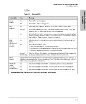
... Link LED will also blink simultaneously. One of the Switch LEDs Table 1-1. Indicates that the port Mode LEDs are lit for ports that the port Mode LEDs are no active network cable is connected to the port • the port is not receiving link beat (RJ-45 ports), or sufficient light (transceiver port) • for Port 25 (transceiver port), the transceiver has failed Blinking* If the Port 25 Link LED is powered on or reset, at 100 Mbps. * The blinking behavior is configured...
... Link LED will also blink simultaneously. One of the Switch LEDs Table 1-1. Indicates that the port Mode LEDs are lit for ports that the port Mode LEDs are no active network cable is connected to the port • the port is not receiving link beat (RJ-45 ports), or sufficient light (transceiver port) • for Port 25 (transceiver port), the transceiver has failed Blinking* If the Port 25 Link LED is powered on or reset, at 100 Mbps. * The blinking behavior is configured...
User Manual
Page 10
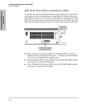
Mode LEDs (one mode to change from one per port) LED Mode Select button and indicator LEDs I If the Full Duplex (FDx) indicator LED is lit, the Mode LED for each port. it flickers as network traffic is indicated by the Mode indicator LEDs near the button. I If the 100 Mbps (100) indicator LED is lit, the Mode LEDs light for those ports that are operating in full duplex. The operation of the switch ports without...
Mode LEDs (one mode to change from one per port) LED Mode Select button and indicator LEDs I If the Full Duplex (FDx) indicator LED is lit, the Mode LED for each port. it flickers as network traffic is indicated by the Mode indicator LEDs near the button. I If the 100 Mbps (100) indicator LED is lit, the Mode LEDs light for those ports that are operating in full duplex. The operation of the switch ports without...
User Manual
Page 16
... the LEDs on the switch's front panel show correct operation. The Switch 2124 can be up and running. Using the appropriate network cables, connect computers, printers, servers, hubs, other switches, routers, and other network devices to the nearby AC power source. 6. See page 2-7. 4. Mount the switch. Once the switch is mounted, plug it may be installing the switch is properly prepared including having a good location for the switch. The Switch 2124 has...
... the LEDs on the switch's front panel show correct operation. The Switch 2124 can be up and running. Using the appropriate network cables, connect computers, printers, servers, hubs, other switches, routers, and other network devices to the nearby AC power source. 6. See page 2-7. 4. Mount the switch. Once the switch is mounted, plug it may be installing the switch is properly prepared including having a good location for the switch. The Switch 2124 has...

User Manual
Page 27
... Link LED does not go on when the network cable is connected to the port, see the documentation accompanying the transceiver for information on connecting fiber-optic cables to the transceiver, and for all the switch ports, when a network cable from the network devices or your patch panels to the fixed RJ-45 ports on the plug clicks into place. See "Diagnosing with the LEDs" in general for fiber-optic cabling configurations. Installing...
... Link LED does not go on when the network cable is connected to the port, see the documentation accompanying the transceiver for information on connecting fiber-optic cables to the transceiver, and for all the switch ports, when a network cable from the network devices or your patch panels to the fixed RJ-45 ports on the plug clicks into place. See "Diagnosing with the LEDs" in general for fiber-optic cabling configurations. Installing...
User Manual
Page 31
... to troubleshoot your troubleshooting: I HP Customer Support Services (page 3-6) Basic Troubleshooting Tips Most problems are caused by the following situations. An HP 100-FX SC Transceiver installed in compliance with the LEDs (page 3-3) I hardware diagnostic tests (page 3-5) I Connecting the RJ-45 ports to devices that all devices connected to the Switch 2124 RJ-45 ports are configured to auto negotiate, or are configured to any other devices. Check for these items first when starting your Switch...
... to troubleshoot your troubleshooting: I HP Customer Support Services (page 3-6) Basic Troubleshooting Tips Most problems are caused by the following situations. An HP 100-FX SC Transceiver installed in compliance with the LEDs (page 3-3) I hardware diagnostic tests (page 3-5) I Connecting the RJ-45 ports to devices that all devices connected to the Switch 2124 RJ-45 ports are configured to auto negotiate, or are configured to any other devices. Check for these items first when starting your Switch...

User Manual
Page 32
... that link could have network problems after recent changes to the network, change back to the cable in appendix B, "Switch Ports and Network Cables" for pinouts and correct cable wiring. If that does not correct the problem, try a different cable. I Faulty or loose cables. Example topologies are secure. Look for every 100Base-TX network installation. For more information on possible network problems and their solutions, refer to the technical note "Troubleshooting LAN Performance and Intermittent Connectivity Problems...
... that link could have network problems after recent changes to the network, change back to the cable in appendix B, "Switch Ports and Network Cables" for pinouts and correct cable wiring. If that does not correct the problem, try a different cable. I Faulty or loose cables. Example topologies are secure. Look for every 100Base-TX network installation. For more information on possible network problems and their solutions, refer to the technical note "Troubleshooting LAN Performance and Intermittent Connectivity Problems...

User Manual
Page 33
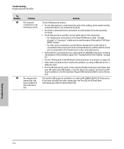
... the switch. Table 3-1. Solution 1. If the Power LED is plugged into an active power source and to get assistance. Or try a different power cord. Try power cycling the switch. Refer to get assistance. LED Error Indicators LED Pattern Indicating Problems Power Off with the LEDs Table 3-1 shows LED patterns on /off cycle once every 1.6 seconds, approximately. A switch hardware failure has occurred during self test. Call your HP-authorized LAN dealer, or use the electronic support services from HP...
... the switch. Table 3-1. Solution 1. If the Power LED is plugged into an active power source and to get assistance. Or try a different power cord. Try power cycling the switch. Refer to get assistance. LED Error Indicators LED Pattern Indicating Problems Power Off with the LEDs Table 3-1 shows LED patterns on /off cycle once every 1.6 seconds, approximately. A switch hardware failure has occurred during self test. Call your HP-authorized LAN dealer, or use the electronic support services from HP...
User Manual
Page 34
... connected device and switch are both powered on page 3-6. • If the other transceiver, the Port 25 Link LED will blink simultaneously with the switch Fault LED. See "Testing Twisted-Pair Cabling" on page 3-5. • Try the "Testing End-to the transmit port on the connected device. • Verify that the connected devices comply with the LEDs Tip Number ˜ Problem The network connection is not working properly. ™ An unsupported transceiver has been installed...
... connected device and switch are both powered on page 3-6. • If the other transceiver, the Port 25 Link LED will blink simultaneously with the switch Fault LED. See "Testing Twisted-Pair Cabling" on page 3-5. • Try the "Testing End-to the transmit port on the connected device. • Verify that the connected devices comply with the LEDs Tip Number ˜ Problem The network connection is not working properly. ™ An unsupported transceiver has been installed...
User Manual
Page 35
..., use a qualified cable test device. The twisted-pair cables attached to provide a link or provide an unreliable link between the switch and the connected network device may not be compatible with the IEEE 802.3 10Base-T or 100Base-TX standards. Contact your HP-authorized LAN dealer or your cable is not operating correctly, you can reset the switch to perform its circuitry and operating code. Troubleshooting Hardware Diagnostic Tests Hardware Diagnostic Tests Testing the Switch...
..., use a qualified cable test device. The twisted-pair cables attached to provide a link or provide an unreliable link between the switch and the connected network device may not be compatible with the IEEE 802.3 10Base-T or 100Base-TX standards. Contact your HP-authorized LAN dealer or your cable is not operating correctly, you can reset the switch to perform its circuitry and operating code. Troubleshooting Hardware Diagnostic Tests Hardware Diagnostic Tests Testing the Switch...

User Manual
Page 36
... trouble with services offered by running a link test or Ping test. a test that they offer and with your LAN adapter documentation for information on how to use this test to verify that the entire communication path between which you can run a link-level test or Ping test through the switch, you can provide you with assistance, both with services that sends known data from one network device to -date support information. HP...
... trouble with services offered by running a link test or Ping test. a test that they offer and with your LAN adapter documentation for information on how to use this test to verify that the entire communication path between which you can run a link-level test or Ping test through the switch, you can provide you with assistance, both with services that sends known data from one network device to -date support information. HP...

User Manual
Page 40
... port and connects correctly. They automatically detect the type of port on the Switch 2124 all have to use a correctly wired crossover cable, though, the switch will still be used - Switch Ports and Network Cables Switch Ports and Network Cables Twisted-Pair Cable/Connector Pin-Outs Cables Twisted-Pair 10 Mbps Operation Category 3, 4, or 5 100-ohm differential unshielded twistedpair (UTP) or shielded twisted-pair (STP) cable, complying with IEEE 802.3 10Base-T specifications...
... port and connects correctly. They automatically detect the type of port on the Switch 2124 all have to use a correctly wired crossover cable, though, the switch will still be used - Switch Ports and Network Cables Switch Ports and Network Cables Twisted-Pair Cable/Connector Pin-Outs Cables Twisted-Pair 10 Mbps Operation Category 3, 4, or 5 100-ohm differential unshielded twistedpair (UTP) or shielded twisted-pair (STP) cable, complying with IEEE 802.3 10Base-T specifications...

User Manual
Page 42
... may be wired as a twisted pair to hubs or other switches, you can use "straight-through" cables. Pins 4, 5, 7, and 8 are not used in the cable. Switch Ports and Network Cables Switch Ports and Network Cables Twisted-Pair Cable/Connector Pin-Outs Straight-Through Twisted-Pair Cable for 10 Mbps or 100 Mbps Network Connections Because of the "HP Auto-MDIX" operation of the 10/100 ports on connector "B". Cable Diagram Connector "A" Connector "B" Straight-Through...
... may be wired as a twisted pair to hubs or other switches, you can use "straight-through" cables. Pins 4, 5, 7, and 8 are not used in the cable. Switch Ports and Network Cables Switch Ports and Network Cables Twisted-Pair Cable/Connector Pin-Outs Straight-Through Twisted-Pair Cable for 10 Mbps or 100 Mbps Network Connections Because of the "HP Auto-MDIX" operation of the 10/100 ports on connector "B". Cable Diagram Connector "A" Connector "B" Straight-Through...

User Manual
Page 55
... 2-4 ports, cables used with ... 2-4 10Base-T connections, length limitations ... 2-4 ports, cables used with ... 2-4 A address learning ... 1-6 address table automatic address learning ... 1-6 filtering out traffic ... 1-7 flooding traffic ... 1-7 forwarding traffic ... 1-7 moves and changes ... 1-7 operation ... 1-6 Auto-MDIX see HP Auto-MDIX B back of switch description ... 1-5 power connector ... 1-5 backbone switch topology with ... 2-16 basic troubleshooting tips ... 3-1 blinking LEDs error indications ... 3-3 buttons LED Mode Select button ... 1-4 Reset button ... 1-2 C cabinet mounting...
... 2-4 ports, cables used with ... 2-4 10Base-T connections, length limitations ... 2-4 ports, cables used with ... 2-4 A address learning ... 1-6 address table automatic address learning ... 1-6 filtering out traffic ... 1-7 flooding traffic ... 1-7 forwarding traffic ... 1-7 moves and changes ... 1-7 operation ... 1-6 Auto-MDIX see HP Auto-MDIX B back of switch description ... 1-5 power connector ... 1-5 backbone switch topology with ... 2-16 basic troubleshooting tips ... 3-1 blinking LEDs error indications ... 3-3 buttons LED Mode Select button ... 1-4 Reset button ... 1-2 C cabinet mounting...

User Manual
Page 56
...L LED Mode Select button ... 1-4 indicator LEDs ... 1-3 LEDs behavior during self test ... 2-7 blinking definition ... 1-3 checking during troubleshooting ... 3-5 descriptions of switch 10/100Base-TX ports ... 1-2 description ... 1-2 LED Mode Select button and LEDs ... 1-4 network ports ... 1-2 Reset button ... 1-2 slot for transceiver module ... 1-2 H horizontal surface, mounting switch on ... 2-12 HP Auto-MDIX description ... 1-6 effect on cable usage ... 2-4, 2-14-2-15, B-2 I included parts ... 2-1 installation connecting the switch to a power source ... 2-12 mounting switch in a rack or...
...L LED Mode Select button ... 1-4 indicator LEDs ... 1-3 LEDs behavior during self test ... 2-7 blinking definition ... 1-3 checking during troubleshooting ... 3-5 descriptions of switch 10/100Base-TX ports ... 1-2 description ... 1-2 LED Mode Select button and LEDs ... 1-4 network ports ... 1-2 Reset button ... 1-2 slot for transceiver module ... 1-2 H horizontal surface, mounting switch on ... 2-12 HP Auto-MDIX description ... 1-6 effect on cable usage ... 2-4, 2-14-2-15, B-2 I included parts ... 2-1 installation connecting the switch to a power source ... 2-12 mounting switch in a rack or...

User Manual
Page 57
... on switch ... 1-2 resetting the switch location of switch installation ... 2-2 switch connecting to a power source ... 2-12 description ... 1-1 electrical specifications ... C-1 safety specifications ... A-1 switch operation address table ... 1-6 description ... 1-6 filtering out traffic ... 1-7 flooding traffic ... 1-7 forwarding traffic ... 1-7 network moves and changes ... 1-7 verifying after installation ... 2-6 T testing checking the LEDs ... 3-5 diagnostic tests ... 3-5 end-to ... 2-12 precautions mounting the switch ... 2-3 power requirements ... 2-3 R rack mounting precautions...
... on switch ... 1-2 resetting the switch location of switch installation ... 2-2 switch connecting to a power source ... 2-12 description ... 1-1 electrical specifications ... C-1 safety specifications ... A-1 switch operation address table ... 1-6 description ... 1-6 filtering out traffic ... 1-7 flooding traffic ... 1-7 forwarding traffic ... 1-7 network moves and changes ... 1-7 verifying after installation ... 2-6 T testing checking the LEDs ... 3-5 diagnostic tests ... 3-5 end-to ... 2-12 precautions mounting the switch ... 2-3 power requirements ... 2-3 R rack mounting precautions...
Brochure
Page 2
ProCurve Switch 2124 Features and benefits Connectivity • 24 auto-sensing 10/100 ports: provide high-performance switching • ProCurve Auto-MDIX: automatically adjusts for straight-through or crossover cables on all 10/100 ports • Full scalability: optional 100Base-FX fiber-optic (full-duplex bandwidth) transceiver enables low-cost uplink connectivity into a wiring closet up to 2 km away Performance • Low-cost/High-performance...
ProCurve Switch 2124 Features and benefits Connectivity • 24 auto-sensing 10/100 ports: provide high-performance switching • ProCurve Auto-MDIX: automatically adjusts for straight-through or crossover cables on all 10/100 ports • Full scalability: optional 100Base-FX fiber-optic (full-duplex bandwidth) transceiver enables low-cost uplink connectivity into a wiring closet up to 2 km away Performance • Low-cost/High-performance...


