
User Manual
Page 5
Prepare the Installation Site 2-5 Cabling Infrastructure 2-5 Installation Location 2-6 2.Install Switch Modules 2-7 3. (Optional) Install Second Power Supply 2-9 4. Connect the Switch to a Power Source 2-18 7. Connect the Network Devices 2-18 iii... 2-13 Horizontal Surface Mounting 2-16 Wall Mounting 2-17 6. Verify the Switch Passes Self Test 2-11 LED Behavior 2-12 5. Contents 1 Introducing the HP ProCurve Series 4100gl Switches Front of the Switch 1-4 LEDs 1-5 LED Mode Select Button and Indicator LEDs 1-7 Console Port 1-8 Reset Button 1-8 Clear Button...
Prepare the Installation Site 2-5 Cabling Infrastructure 2-5 Installation Location 2-6 2.Install Switch Modules 2-7 3. (Optional) Install Second Power Supply 2-9 4. Connect the Switch to a Power Source 2-18 7. Connect the Network Devices 2-18 iii... 2-13 Horizontal Surface Mounting 2-16 Wall Mounting 2-17 6. Verify the Switch Passes Self Test 2-11 LED Behavior 2-12 5. Contents 1 Introducing the HP ProCurve Series 4100gl Switches Front of the Switch 1-4 LEDs 1-5 LED Mode Select Button and Indicator LEDs 1-7 Console Port 1-8 Reset Button 1-8 Clear Button...

User Manual
Page 6
...(Optional) Connect a Console to the Switch 2-19 Terminal Configuration 2-19 Direct Console Access 2-20 Telnet Console Access 2-20 Hot Swapping Switch Modules 2-21 Adding or Replacing Modules 2-21 Changing the Module Type 2-21 Example Network Topologies 2-22 Basic Connectivity 2-22 Use as an Edge Switch 2-23 Stacking the Switches 2-24 3 Getting Started With... Switch-to-Device Network Communications 4-11 Testing End-to-End Network Communications 4-11 Restoring the Factory Default Configuration 4-12 Downloading New Code 4-13 HP Customer Support Services 4-13 iv
...(Optional) Connect a Console to the Switch 2-19 Terminal Configuration 2-19 Direct Console Access 2-20 Telnet Console Access 2-20 Hot Swapping Switch Modules 2-21 Adding or Replacing Modules 2-21 Changing the Module Type 2-21 Example Network Topologies 2-22 Basic Connectivity 2-22 Use as an Edge Switch 2-23 Stacking the Switches 2-24 3 Getting Started With... Switch-to-Device Network Communications 4-11 Testing End-to-End Network Communications 4-11 Restoring the Factory Default Configuration 4-12 Downloading New Code 4-13 HP Customer Support Services 4-13 iv
User Manual
Page 9
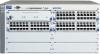
... chassis (J4887A) or as the Switch 4148gl (J4888A) with two 10/100-TX gl Modules preinstalled � � � 1-1 HP ProCurve Switch4104gl (J4887A) � � � HP ProCurve Switch 4148gl (J4888A) with two 24port 10/100-TX gl Modules pre-installed. They are store-and-forward devices that can be used to build high...
... chassis (J4887A) or as the Switch 4148gl (J4888A) with two 10/100-TX gl Modules preinstalled � � � 1-1 HP ProCurve Switch4104gl (J4887A) � � � HP ProCurve Switch 4148gl (J4888A) with two 24port 10/100-TX gl Modules pre-installed. They are store-and-forward devices that can be used to build high...

User Manual
Page 10
...) with one 3-port Gigabit Transceiver gl Module and three 24-port 10/100-TX gl Modules pre-installed. HP ProCurve Switch4108gl (J4865A) HP ProCurve Switch 4108gl Bundle (J4861A) with one Gigabit Transceiver gl Module and three 10/100-TX gl Modules preinstalled � � � ... �� �� �� �� �� �� 1-2 Introducing the HP ProCurve Series 4100gl Switches Introducing the HP ProCurve Series 4100gl Switches Switch 4108gl and Bundle.
...) with one 3-port Gigabit Transceiver gl Module and three 24-port 10/100-TX gl Modules pre-installed. HP ProCurve Switch4108gl (J4865A) HP ProCurve Switch 4108gl Bundle (J4861A) with one Gigabit Transceiver gl Module and three 10/100-TX gl Modules preinstalled � � � ... �� �� �� �� �� �� 1-2 Introducing the HP ProCurve Series 4100gl Switches Introducing the HP ProCurve Series 4100gl Switches Switch 4108gl and Bundle.

User Manual
Page 11
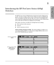
...;� �� �� �� �� See "Switch Features" on page 1-10 for a list of the switch modules that you can install in the HP ProCurve Series 4100gl Switches (modules available when this switch to provide dedicated bandwidth to this manual was printed). The Switch 4160gl (J8152A) is available as...
...;� �� �� �� �� See "Switch Features" on page 1-10 for a list of the switch modules that you can install in the HP ProCurve Series 4100gl Switches (modules available when this switch to provide dedicated bandwidth to this manual was printed). The Switch 4160gl (J8152A) is available as...

User Manual
Page 12
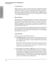
... Series 4100gl Switches Introducing the HP ProCurve Series 4100gl Switches Front of the Switch Front of the Switch Console Port Power and Fault LEDs Reset and Clear buttons Status LEDs for the Fans, Power Supplies, and Switch Modules LED Mode Select button and indicator LEDs... �� �� �� �� Self Test LED Switch Modules and slots with Link and Mode LEDs for each port located on each module This illustration shows the 4108gl Bundle, but the labeling and descriptions apply to all of the...
... Series 4100gl Switches Introducing the HP ProCurve Series 4100gl Switches Front of the Switch Front of the Switch Console Port Power and Fault LEDs Reset and Clear buttons Status LEDs for the Fans, Power Supplies, and Switch Modules LED Mode Select button and indicator LEDs... �� �� �� �� Self Test LED Switch Modules and slots with Link and Mode LEDs for each port located on each module This illustration shows the 4108gl Bundle, but the labeling and descriptions apply to all of the...

User Manual
Page 13
...the fault will be flashing simultaneously. The normal operational state; indicates that component, for that there are operating normally. A component of the switch modules, a power supply, or a fan. Switch Chassis LEDs LEDs Power (green) Fault (orange) State On Off Off Flashing† On Self... a prolonged time, the switch has encountered a fatal hardware failure, or has failed its self test. Introducing the HP ProCurve Series 4100gl Switches Introducing the HP ProCurve Series 4100gl Switches Front of the Switch LEDs As described in to an active AC power source. the switch ...
...the fault will be flashing simultaneously. The normal operational state; indicates that component, for that there are operating normally. A component of the switch modules, a power supply, or a fan. Switch Chassis LEDs LEDs Power (green) Fault (orange) State On Off Off Flashing† On Self... a prolonged time, the switch has encountered a fatal hardware failure, or has failed its self test. Introducing the HP ProCurve Series 4100gl Switches Introducing the HP ProCurve Series 4100gl Switches Front of the Switch LEDs As described in to an active AC power source. the switch ...

User Manual
Page 14
... powered on /off cycle once every 1.6 seconds, approximately. Off Flashing† One of the Switch LEDs State Meaning Status/ On Modules (green - Introducing the HP ProCurve Series 4100gl Switches Introducing the HP ProCurve Series 4100gl Switches Front of these conditions exists: • no active network cable is an on/off cycle once every...
... powered on /off cycle once every 1.6 seconds, approximately. Off Flashing† One of the Switch LEDs State Meaning Status/ On Modules (green - Introducing the HP ProCurve Series 4100gl Switches Introducing the HP ProCurve Series 4100gl Switches Front of these conditions exists: • no active network cable is an on/off cycle once every...
User Manual
Page 16
...that can be run on a PC emulating a VT-100 terminal, or on page 2-21. Press the Reset button also after changing the module type that is installed in chapter 2, "Installing the Series 4100gl Switches". When pressed with the Reset button in chapter 4, "Troubleshooting" of this...console access passwords that if you are displayed in a secure location, such as HP ProCurve Manager for the following purposes: ■ Deleting Passwords - Introducing the HP ProCurve Series 4100gl Switches Introducing the HP ProCurve Series 4100gl Switches Front of the Switch Console Port This port is used ...
...that can be run on a PC emulating a VT-100 terminal, or on page 2-21. Press the Reset button also after changing the module type that is installed in chapter 2, "Installing the Series 4100gl Switches". When pressed with the Reset button in chapter 4, "Troubleshooting" of this...console access passwords that if you are displayed in a secure location, such as HP ProCurve Manager for the following purposes: ■ Deleting Passwords - Introducing the HP ProCurve Series 4100gl Switches Introducing the HP ProCurve Series 4100gl Switches Front of the Switch Console Port This port is used ...

User Manual
Page 18
...can be "hot swapped". ■ the supported HP ProCurve transceivers can be hot swapped into which you can install the supported mini-GBICs, the HP Gigabit-SX LC mini-GBIC (J4858A) and the HP Gigabit-LX LC mini-GBIC (J4859A) • 20-port Gig-T gl module with 2 mini-GBIC Gig ports (J4908A) The... Switch 4108gl Bundle has one Gigabit Transceiver gl Module and three 10/100-TX gl Modules preinstalled, and the Switch ...
...can be "hot swapped". ■ the supported HP ProCurve transceivers can be hot swapped into which you can install the supported mini-GBICs, the HP Gigabit-SX LC mini-GBIC (J4858A) and the HP Gigabit-LX LC mini-GBIC (J4859A) • 20-port Gig-T gl module with 2 mini-GBIC Gig ports (J4908A) The... Switch 4108gl Bundle has one Gigabit Transceiver gl Module and three 10/100-TX gl Modules preinstalled, and the Switch ...

User Manual
Page 22
... Procedures Summary Follow these steps. 1. Please see the installation details for installing a second, load-sharing power supply. The modules are supported. Note: Make sure you will be mounted in a 19-inch telco rack, in the back for more...swappable" though, so they can be installing the switch is powered on where you use only HP ProCurve Switch gl Modules in to install the modules first. Connect power to install it before mounting the switch. 4. The Series 4100gl Switches ... may be easier to the switch (page 2-18). The rest of the HP ProCurve Switch gl modules.
... Procedures Summary Follow these steps. 1. Please see the installation details for installing a second, load-sharing power supply. The modules are supported. Note: Make sure you will be mounted in a 19-inch telco rack, in the back for more...swappable" though, so they can be installing the switch is powered on where you use only HP ProCurve Switch gl Modules in to install the modules first. Connect power to install it before mounting the switch. 4. The Series 4100gl Switches ... may be easier to the switch (page 2-18). The rest of the HP ProCurve Switch gl modules.

User Manual
Page 23
... from an SNMP network management station. Warnings Installation Precautions Follow these installation steps. A cover plate is installed on the 100/1000-T gl Module comply with the heaviest device at the bottom and progressively lighter devices installed above. Continued on page 2-18. Note: The 10/100Base-TX... ports on the 10/100-TX gl Module have the HP Auto-MDIX feature, and the 100/1000Base-T ports on any of your twisted-pair network connections. 8. (Optional) Connect a console to...
... from an SNMP network management station. Warnings Installation Precautions Follow these installation steps. A cover plate is installed on the 100/1000-T gl Module comply with the heaviest device at the bottom and progressively lighter devices installed above. Continued on page 2-18. Note: The 10/100Base-TX... ports on the 10/100-TX gl Module have the HP Auto-MDIX feature, and the 100/1000Base-T ports on any of your twisted-pair network connections. 8. (Optional) Connect a console to...

User Manual
Page 24
...ampere ratings are properly grounded, then use a power cord displaying the mark of the safety agency that for any switch slot into which no module is installed, or any transceiver slot into which no transceiver is installed, the cover plate is required for the switch's current requirements. Installing...(continued) ■ Ensure the power source circuits are usually printed on the devices near the switch and should never have more than one module slot uncovered at a time while the switch is adequately sized for safe operation, and to use the power cord supplied with the rating limit...
...ampere ratings are properly grounded, then use a power cord displaying the mark of the safety agency that for any switch slot into which no module is installed, or any transceiver slot into which no transceiver is installed, the cover plate is required for the switch's current requirements. Installing...(continued) ■ Ensure the power source circuits are usually printed on the devices near the switch and should never have more than one module slot uncovered at a time while the switch is adequately sized for safe operation, and to use the power cord supplied with the rating limit...

User Manual
Page 26
... is equivalent to 550 meters depending on the cable used , but a modeconditioning patch cord may be needed - See the Installation Guide that came with your module for • 70 kilometers Gigabit-LX. Between the transmit and receive ends of the cable, at least 5db. See "Fiber-Optic Cables" on page B-3 for...
... is equivalent to 550 meters depending on the cable used , but a modeconditioning patch cord may be needed - See the Installation Guide that came with your module for • 70 kilometers Gigabit-LX. Between the transmit and receive ends of the cable, at least 5db. See "Fiber-Optic Cables" on page B-3 for...

User Manual
Page 27
... they will be immediately operational. For installation details, see the instructions in place. ■ If you install only HP ProCurve Switch gl Modules. See "Hot Swapping the Switch Module" on , and normally will not operate. Switch xl Modules will fit into the slots as shown in any electrostatic discharge problems by handling the...
... they will be immediately operational. For installation details, see the instructions in place. ■ If you install only HP ProCurve Switch gl Modules. See "Hot Swapping the Switch Module" on , and normally will not operate. Switch xl Modules will fit into the slots as shown in any electrostatic discharge problems by handling the...

User Manual
Page 28
Installing the Series 4100gl Switches Installation Procedures 1. Installing the Series 4100gl Switches The module is fully inserted when the module bulkhead is not needed and should not be used. High insertion force is contacting, or very close to contacting the face of the switch. For best results, push near both screws. 2. Then tighten the retaining screws on the module until it is fully inserted. Insert module into the guides and slide it in until they are secure, but do not overtighten them. 2-8 "Low-force" connector.
Installing the Series 4100gl Switches Installation Procedures 1. Installing the Series 4100gl Switches The module is fully inserted when the module bulkhead is not needed and should not be used. High insertion force is contacting, or very close to contacting the face of the switch. For best results, push near both screws. 2. Then tighten the retaining screws on the module until it is fully inserted. Insert module into the guides and slide it in until they are secure, but do not overtighten them. 2-8 "Low-force" connector.

User Manual
Page 31
... page. Verify the Switch Passes Self Test After you should first verify that it is described on the back of the switch modules. They are powered on for diagnostic help. 2-11 Installing the Series 4100gl Switches Note Connect power cord to power connector The ...LED behavior is working properly by plugging it into a power source and verifying that it passes its network location, you have installed any modules and the optional second power supply, but before mounting the switch in its self test. Installing the Series 4100gl Switches Installation Procedures 4. Connect...
... page. Verify the Switch Passes Self Test After you should first verify that it is described on the back of the switch modules. They are powered on for diagnostic help. 2-11 Installing the Series 4100gl Switches Note Connect power cord to power connector The ...LED behavior is working properly by plugging it into a power source and verifying that it passes its network location, you have installed any modules and the optional second power supply, but before mounting the switch in its self test. Installing the Series 4100gl Switches Installation Procedures 4. Connect...

User Manual
Page 32
..., depending on , it performs its diagnostic self test. The entire download, initialization, and self test process can take up to the modules is powered on the number and type of the self test, the Self Test LED stays on . LED Behavior: During the self ... . You may see each port Link LED flash briefly, in the switch. Installing the Series 4100gl Switches Installing the Series 4100gl Switches Installation Procedures switch module LEDs: Link and Mode LEDs for each port Switch Chassis LEDs � � � � � � � � &#...
..., depending on , it performs its diagnostic self test. The entire download, initialization, and self test process can take up to the modules is powered on the number and type of the self test, the Self Test LED stays on . LED Behavior: During the self ... . You may see each port Link LED flash briefly, in the switch. Installing the Series 4100gl Switches Installing the Series 4100gl Switches Installation Procedures switch module LEDs: Link and Mode LEDs for each port Switch Chassis LEDs � � � � � � � � &#...

User Manual
Page 33
... screws. Installing the Series 4100gl Switches Caution Installing the Series 4100gl Switches Installation Procedures ■ The port LEDs on the switch modules go into their normal operational mode: • If the ports are installing the switch in an equipment cabinet, please see the "...in a rack or cabinet ■ on a horizontal surface ■ on page 2-3 before mounting the switch. 1. Mount the Switch After the modules and optional power supply are installed and you have verified that are designed to the switch with three screws as shown in an equipment cabinet...
... screws. Installing the Series 4100gl Switches Caution Installing the Series 4100gl Switches Installation Procedures ■ The port LEDs on the switch modules go into their normal operational mode: • If the ports are installing the switch in an equipment cabinet, please see the "...in a rack or cabinet ■ on a horizontal surface ■ on page 2-3 before mounting the switch. 1. Mount the Switch After the modules and optional power supply are installed and you have verified that are designed to the switch with three screws as shown in an equipment cabinet...

User Manual
Page 37
... switch to the wall or wood surface with the switch allow you to a wall or wood surface that is with the unit upright and the modules facing out, as shown in a similar way. The illustrations below .
... switch to the wall or wood surface with the switch allow you to a wall or wood surface that is with the unit upright and the modules facing out, as shown in a similar way. The illustrations below .
