End User License Agreement
Page 2
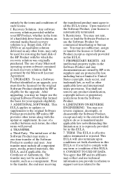
entirely by the terms and conditions of the HP Product with/for which the recovery solution was originally purchased. floppy disk, CD or DVD) or an equivalent solution delivered in the form of the Software Product, your upgrade eligibility. 3. This EULA applies to updates or supplements to ...the extent that formed the basis for your HP Product, whether in any other terms along with any term or condition of this EULA....
entirely by the terms and conditions of the HP Product with/for which the recovery solution was originally purchased. floppy disk, CD or DVD) or an equivalent solution delivered in the form of the Software Product, your upgrade eligibility. 3. This EULA applies to updates or supplements to ...the extent that formed the basis for your HP Product, whether in any other terms along with any term or condition of this EULA....

Upgrading and Servicing Guide
Page 5
..., and other information about the computer. It is recommended that you use a magnetic-tipped screwdriver when opening and closing the HP TouchSmart PC, to make it easier to upgrade or service the HP TouchSmart PC. Hewlett-Packard recommends that you use an antistatic wrist strap and stand on a conductive foam pad when working on the...
..., and other information about the computer. It is recommended that you use a magnetic-tipped screwdriver when opening and closing the HP TouchSmart PC, to make it easier to upgrade or service the HP TouchSmart PC. Hewlett-Packard recommends that you use an antistatic wrist strap and stand on a conductive foam pad when working on the...

Upgrading and Servicing Guide
Page 6
...Back cover D: Computer stand G: Hard drive/memory cover E: Power adapter connector H: Connector cover F: Wireless keyboard and mouse receiver 2 Upgrading and Servicing Guide The computer is heavy. Locating Components Refer to the following illustration to the electrical power system. WARNING: Take care when... lifting or moving your system to locate components of the HP TouchSmart PC. WARNING: Avoid touching sharp edges inside the computer. Safety Information This product has not been evaluated for connection to...
...Back cover D: Computer stand G: Hard drive/memory cover E: Power adapter connector H: Connector cover F: Wireless keyboard and mouse receiver 2 Upgrading and Servicing Guide The computer is heavy. Locating Components Refer to the following illustration to the electrical power system. WARNING: Take care when... lifting or moving your system to locate components of the HP TouchSmart PC. WARNING: Avoid touching sharp edges inside the computer. Safety Information This product has not been evaluated for connection to...

Upgrading and Servicing Guide
Page 7
...allow the internal system components to cool before touching them. 3 After the system has completely shut down, disconnect the power adapter (A) from the HP TouchSmart PC. Opening the Computer To avoid injury and equipment damage, always complete the following steps in order, when opening the... a grounded metal object. 2 Tap the Windows Vista start button™ , and then tap Shut Down. Ensure that you are discharged of the HP TouchSmart PC. CAUTION: Static electricity can damage the electronic components of the HP TouchSmart PC or optional equipment. A Upgrading and Servicing Guide 3
...allow the internal system components to cool before touching them. 3 After the system has completely shut down, disconnect the power adapter (A) from the HP TouchSmart PC. Opening the Computer To avoid injury and equipment damage, always complete the following steps in order, when opening the... a grounded metal object. 2 Tap the Windows Vista start button™ , and then tap Shut Down. Ensure that you are discharged of the HP TouchSmart PC. CAUTION: Static electricity can damage the electronic components of the HP TouchSmart PC or optional equipment. A Upgrading and Servicing Guide 3

Upgrading and Servicing Guide
Page 8
4 Remove the connector cover by inserting your finger under the gap on the bottom-left side of the HP TouchSmart PC. 6 Place the computer face-down a blanket, towel, or other damage. 4 Upgrading and Servicing Guide HP recommends that you set down on a soft flat surface. A 5 Disconnect all other attached cables from scratches or other soft cloth to protect the touch screen surface from the back of the cover (A), and then pulling gently.
4 Remove the connector cover by inserting your finger under the gap on the bottom-left side of the HP TouchSmart PC. 6 Place the computer face-down a blanket, towel, or other damage. 4 Upgrading and Servicing Guide HP recommends that you set down on a soft flat surface. A 5 Disconnect all other attached cables from scratches or other soft cloth to protect the touch screen surface from the back of the cover (A), and then pulling gently.

Upgrading and Servicing Guide
Page 9
B A 8 Remove the screw that secures the hard disk drive/memory cover to the right until it is in the locked position (B). Upgrading and Servicing Guide 5 7 Apply additional pressure to lift the computer stand as far as it will go to an upright position, about 90 degrees (A) from the computer, and then move the latch to the back of the computer.
B A 8 Remove the screw that secures the hard disk drive/memory cover to the right until it is in the locked position (B). Upgrading and Servicing Guide 5 7 Apply additional pressure to lift the computer stand as far as it will go to an upright position, about 90 degrees (A) from the computer, and then move the latch to the back of the computer.

Upgrading and Servicing Guide
Page 10
To replace a hard disk drive, see "Removing and Replacing a Memory Module" on page 14. 6 Upgrading and Servicing Guide 9 Insert your fingertips just under the cover, and then pull up firmly to release the tabs. 10 Slide the cover out toward you to remove it, and then set it aside. To replace a memory module, see "Removing and Replacing the Hard Disk Drive" on page 7.
To replace a hard disk drive, see "Removing and Replacing a Memory Module" on page 14. 6 Upgrading and Servicing Guide 9 Insert your fingertips just under the cover, and then pull up firmly to release the tabs. 10 Slide the cover out toward you to remove it, and then set it aside. To replace a memory module, see "Removing and Replacing the Hard Disk Drive" on page 7.

Upgrading and Servicing Guide
Page 11
Before you can replace. Removing and Replacing a Memory Module Your HP TouchSmart PC comes with the key slot circled is shown in -line memory modules). Upgrading and Servicing Guide 7 A memory module with random access memory (RAM), which type and speed of memory module your computer. The motherboard contains sockets for specific memory module information and...
Before you can replace. Removing and Replacing a Memory Module Your HP TouchSmart PC comes with the key slot circled is shown in -line memory modules). Upgrading and Servicing Guide 7 A memory module with random access memory (RAM), which type and speed of memory module your computer. The motherboard contains sockets for specific memory module information and...

Upgrading and Servicing Guide
Page 12
B A CAUTION: When handling a memory module, be careful not to remove the module. 8 Upgrading and Servicing Guide CAUTION: Do not pull the memory module out of the way (B). Use the latches of the retaining clips to touch any of the contacts. Doing so may damage the module. Removing a Memory Module 1 Before you begin this procedure, follow the procedures in "Start Here" on page 1. 2 Locate the memory module EMI shield (A), hook a finger through the shield loop, and then lift it up and out of the socket.
B A CAUTION: When handling a memory module, be careful not to remove the module. 8 Upgrading and Servicing Guide CAUTION: Do not pull the memory module out of the way (B). Use the latches of the retaining clips to touch any of the contacts. Doing so may damage the module. Removing a Memory Module 1 Before you begin this procedure, follow the procedures in "Start Here" on page 1. 2 Locate the memory module EMI shield (A), hook a finger through the shield loop, and then lift it up and out of the socket.

Upgrading and Servicing Guide
Page 13
Both memory modules can be easier to push one latch at an angle. Note the key slot on the connector edge. 5 Store the memory module in antistatic packaging. It may be removed by using the same procedure. 4 Lift the memory module from the memory module. Upgrading and Servicing Guide 9 3 Push the two latches of the retaining clips away from the memory socket. The memory module pops up at a time.
Both memory modules can be easier to push one latch at an angle. Note the key slot on the connector edge. 5 Store the memory module in antistatic packaging. It may be removed by using the same procedure. 4 Lift the memory module from the memory module. Upgrading and Servicing Guide 9 3 Push the two latches of the retaining clips away from the memory socket. The memory module pops up at a time.

Upgrading and Servicing Guide
Page 14
... are keyed. Replacing a Memory Module Upgrade the memory in your HP TouchSmart PC with the socket, so that the key slot on the connector edge is the same as the memory originally installed. If the module slot does not match the socket, turn the memory module over. 10 Upgrading and Servicing Guide The capacity...
... are keyed. Replacing a Memory Module Upgrade the memory in your HP TouchSmart PC with the socket, so that the key slot on the connector edge is the same as the memory originally installed. If the module slot does not match the socket, turn the memory module over. 10 Upgrading and Servicing Guide The capacity...

Upgrading and Servicing Guide
Page 15
A Upgrading and Servicing Guide 11 In the following illustration, a memory module is installed incorrectly (A), with the gold edge showing. CAUTION: The memory module must be inserted all the way into the memory slot, until the retaining clips snap into place. otherwise it is snapped down the outer edge of the memory module until the gold edge is almost completely hidden in the slot, and then push down into place; 3 Slide the memory module all the way into the slot before it will not work properly.
A Upgrading and Servicing Guide 11 In the following illustration, a memory module is installed incorrectly (A), with the gold edge showing. CAUTION: The memory module must be inserted all the way into the memory slot, until the retaining clips snap into place. otherwise it is snapped down the outer edge of the memory module until the gold edge is almost completely hidden in the slot, and then push down into place; 3 Slide the memory module all the way into the slot before it will not work properly.
Upgrading and Servicing Guide
Page 16
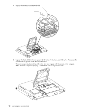
4 Replace the memory module EMI shield. 5 Replace the hard disk drive/memory cover by lowering it into place, and sliding it will be flush with the grooves in the computer. When the cover is replaced properly, it so the slots on the cover fit into place with a click as the side tabs engage with the larger back cover. 12 Upgrading and Servicing Guide The cover snaps into the grooves under the computer stand.
4 Replace the memory module EMI shield. 5 Replace the hard disk drive/memory cover by lowering it into place, and sliding it will be flush with the grooves in the computer. When the cover is replaced properly, it so the slots on the cover fit into place with a click as the side tabs engage with the larger back cover. 12 Upgrading and Servicing Guide The cover snaps into the grooves under the computer stand.
Upgrading and Servicing Guide
Page 17
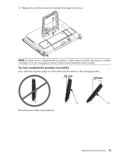
You have completed this procedure successfully! Upgrading and Servicing Guide 13 NOTE: If a blank screen is displayed after you replace or add a memory module, the memory is installed incorrectly, or it is the wrong type of memory. Now, place the computer upright on a flat surface with the stand in a safe and open position. 10° min. 40°max Reconnect power cables and peripherals. Remove and reinstall the memory module. 6 Replace the screw that secures the hard disk drive cage to the chassis.
You have completed this procedure successfully! Upgrading and Servicing Guide 13 NOTE: If a blank screen is displayed after you replace or add a memory module, the memory is installed incorrectly, or it is the wrong type of memory. Now, place the computer upright on a flat surface with the stand in a safe and open position. 10° min. 40°max Reconnect power cables and peripherals. Remove and reinstall the memory module. 6 Replace the screw that secures the hard disk drive cage to the chassis.

Upgrading and Servicing Guide
Page 18
... factory-installed files. B A 14 Upgrading and Servicing Guide The hard disk drive is a Serial ATA (advanced technology attachment) drive, which uses a narrow data cable. Failure to the Limited Warranty, Support, and System Recovery Guide included with your HP TouchSmart PC. Removing and Replacing the Hard... Disk Drive You can replace or upgrade the hard disk drive. CAUTION: Before removing the hard disk drive, back up and out of...
... factory-installed files. B A 14 Upgrading and Servicing Guide The hard disk drive is a Serial ATA (advanced technology attachment) drive, which uses a narrow data cable. Failure to the Limited Warranty, Support, and System Recovery Guide included with your HP TouchSmart PC. Removing and Replacing the Hard... Disk Drive You can replace or upgrade the hard disk drive. CAUTION: Before removing the hard disk drive, back up and out of...

Upgrading and Servicing Guide
Page 19
3 While the hard disk drive is still in the computer, disconnect the power and data cables on the hard disk drive, by pressing down the latches and then removing them from the drive. 4 Remove the shipping screw just to the left of the cables. 5 Pull up on the hard disk drive tab (A), and then pull the drive from its bay (B). A B Upgrading and Servicing Guide 15
3 While the hard disk drive is still in the computer, disconnect the power and data cables on the hard disk drive, by pressing down the latches and then removing them from the drive. 4 Remove the shipping screw just to the left of the cables. 5 Pull up on the hard disk drive tab (A), and then pull the drive from its bay (B). A B Upgrading and Servicing Guide 15

Upgrading and Servicing Guide
Page 20
6 With a Phillips screwdriver (magnetic-tipped recommended), remove the four screws that secure the hard disk drive to the cage, and then slide the hard disk drive out of the cage. Your hard disk drive cage may look slightly different from the illustration. 7 Place the hard disk drive in an anti-static bag. 16 Upgrading and Servicing Guide
6 With a Phillips screwdriver (magnetic-tipped recommended), remove the four screws that secure the hard disk drive to the cage, and then slide the hard disk drive out of the cage. Your hard disk drive cage may look slightly different from the illustration. 7 Place the hard disk drive in an anti-static bag. 16 Upgrading and Servicing Guide
Upgrading and Servicing Guide
Page 21
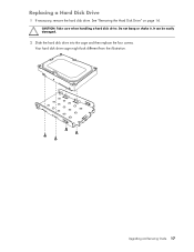
Do not bang or shake it. See "Removing the Hard Disk Drive" on page 14. Upgrading and Servicing Guide 17 Your hard disk drive cage might look different from the illustration. Replacing a Hard Disk Drive 1 If necessary, remove the hard disk drive. CAUTION: Take care when handling a hard disk drive. It can be easily damaged. 2 Slide the hard disk drive into the cage and then replace the four screws.
Do not bang or shake it. See "Removing the Hard Disk Drive" on page 14. Upgrading and Servicing Guide 17 Your hard disk drive cage might look different from the illustration. Replacing a Hard Disk Drive 1 If necessary, remove the hard disk drive. CAUTION: Take care when handling a hard disk drive. It can be easily damaged. 2 Slide the hard disk drive into the cage and then replace the four screws.

Upgrading and Servicing Guide
Page 22
3 Slide the hard disk drive cage into the bay until you hear the click indicating it is engaged. 4 Connect the power and data cables to the hard disk drive. 18 Upgrading and Servicing Guide
3 Slide the hard disk drive cage into the bay until you hear the click indicating it is engaged. 4 Connect the power and data cables to the hard disk drive. 18 Upgrading and Servicing Guide
Upgrading and Servicing Guide
Page 23
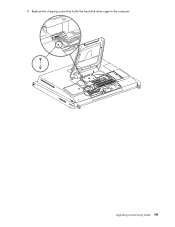
5 Replace the shipping screw that holds the hard disk drive cage to the computer. Upgrading and Servicing Guide 19
5 Replace the shipping screw that holds the hard disk drive cage to the computer. Upgrading and Servicing Guide 19


