Service Guide
Page 14
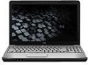
... identification Item Component 1 Internal display switch 2 Wireless antennae (2) (select models only) 3 Integrated webcam light (select models only) 4 Integrated webcam (select models only) 5 Internal microphone Description Turns off the display and initiates Sleep if the display is closed while the power is in Help and Support.
... identification Item Component 1 Internal display switch 2 Wireless antennae (2) (select models only) 3 Integrated webcam light (select models only) 4 Integrated webcam (select models only) 5 Internal microphone Description Turns off the display and initiates Sleep if the display is closed while the power is in Help and Support.
Service Guide
Page 15
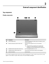
..., the light is not plugged into an external power source, the light stays off until the battery reaches a low battery level. If the computer is turned off when all batteries in Hibernation. ■ On: A battery is charging. ■ Blinking: A battery that is open or closed. The light on the power ...On: The computer is on. ■ Blinking: The computer is in the Sleep state. ■ Off: The computer is off or in the computer are turned off. Blinking: The hard drive or optical drive is being accessed. 4 TouchPad light White: TouchPad is enabled. 5 Caps lock light On: Caps lock is on...
..., the light is not plugged into an external power source, the light stays off until the battery reaches a low battery level. If the computer is turned off when all batteries in Hibernation. ■ On: A battery is charging. ■ Blinking: A battery that is open or closed. The light on the power ...On: The computer is on. ■ Blinking: The computer is in the Sleep state. ■ Off: The computer is off or in the computer are turned off. Blinking: The hard drive or optical drive is being accessed. 4 TouchPad light White: TouchPad is enabled. 5 Caps lock light On: Caps lock is on...
Service Guide
Page 16
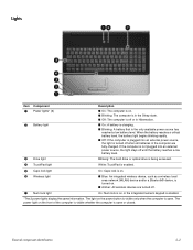
... shutdown procedures are ineffective, press and hold the power button for at least 5 seconds to turn on the computer. ■ When the computer is on or off the computer. External component identification 2-3 Turns the wireless feature on , press the button briefly to initiate Sleep. ■ When the ...computer is in the Sleep state, press the button briefly to exit Sleep. ■ When the computer is off, press the button to turn off , but does not create a wireless connection. ✎ A wireless network must be set up in Help and Support. For information about your...
... shutdown procedures are ineffective, press and hold the power button for at least 5 seconds to turn on the computer. ■ When the computer is on or off the computer. External component identification 2-3 Turns the wireless feature on , press the button briefly to initiate Sleep. ■ When the ...computer is in the Sleep state, press the button briefly to exit Sleep. ■ When the computer is off, press the button to turn off , but does not create a wireless connection. ✎ A wireless network must be set up in Help and Support. For information about your...
Service Guide
Page 19
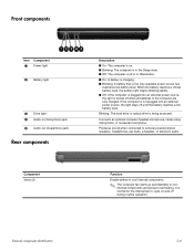
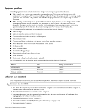
...: The computer is off until the battery reaches a low battery level. If the computer is not plugged into an external power source, the light is turned off during routine operation. Connects an optional computer headset microphone, stereo array microphone, or monaural microphone. Front components Item Component 1 Power light 2 Battery light 3 Drive...
...: The computer is off until the battery reaches a low battery level. If the computer is not plugged into an external power source, the light is turned off during routine operation. Connects an optional computer headset microphone, stereo array microphone, or monaural microphone. Front components Item Component 1 Power light 2 Battery light 3 Drive...
Service Guide
Page 43
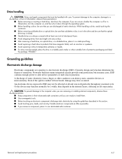
If you are unsure whether the computer is off or in Hibernation, turn the computer on surfaces covered with care. Removal and replacement procedures 4-2 Networks built into many integrated circuits provide some protection, but in the internal layers, ...
If you are unsure whether the computer is off or in Hibernation, turn the computer on surfaces covered with care. Removal and replacement procedures 4-2 Networks built into many integrated circuits provide some protection, but in the internal layers, ...
Service Guide
Page 44
... Removing bubble pack from assemblies in static-safe tubes, bags, or boxes. ■ Protect ESD-sensitive parts and assemblies with pins, leads, or circuitry. ■ Turn off power and input signals before removing items from their containers. ■ Always be degraded by as little as ordinary plastic assembly aids and Styrofoam...
... Removing bubble pack from assemblies in static-safe tubes, bags, or boxes. ■ Protect ESD-sensitive parts and assemblies with pins, leads, or circuitry. ■ Turn off power and input signals before removing items from their containers. ■ Always be degraded by as little as ordinary plastic assembly aids and Styrofoam...
Service Guide
Page 45
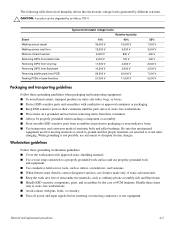
... plastic bags, tubes, or boxes ■ Metal tote boxes ■ Electrostatic voltage levels and protective materials The following grounding equipment is off or in Hibernation, turn the computer on page 4-7). 5. Equipment guidelines Grounding equipment must be used at a grounded workstation. ■ When seated, wear a wrist strap connected to a grounded system. Foot...
... plastic bags, tubes, or boxes ■ Metal tote boxes ■ Electrostatic voltage levels and protective materials The following grounding equipment is off or in Hibernation, turn the computer on page 4-7). 5. Equipment guidelines Grounding equipment must be used at a grounded workstation. ■ When seated, wear a wrist strap connected to a grounded system. Foot...
Service Guide
Page 46
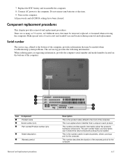
... This is the number used to the bottom of the warranty period for the computer. This number provides specific information about the product's hardware components. Turn on the bottom of the computer. The part number helps a service technician to each screw and standoff size and location during removal and replacement. All...
... This is the number used to the bottom of the warranty period for the computer. This number provides specific information about the product's hardware components. Turn on the bottom of the computer. The part number helps a service technician to each screw and standoff size and location during removal and replacement. All...
Service Guide
Page 48
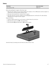
Turn the computer upside down on , and then shut it down the computer. Disconnect the power from the computer by inserting it 3 from the computer. Remove ...-Wh Spare part number 485041-001 Before disassembling the computer, follow these steps: 1. If you are unsure whether the computer is off or in Hibernation, turn the computer on a flat surface, with the battery bay toward you hear a click. Slide the battery release latch 1 to the computer. 3.
Turn the computer upside down on , and then shut it down the computer. Disconnect the power from the computer by inserting it 3 from the computer. Remove ...-Wh Spare part number 485041-001 Before disassembling the computer, follow these steps: 1. If you are unsure whether the computer is off or in Hibernation, turn the computer on a flat surface, with the battery bay toward you hear a click. Slide the battery release latch 1 to the computer. 3.
Service Guide
Page 49
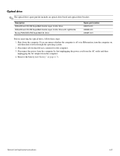
... drive spare part kit includes an optical drive bezel and optical drive bracket. If you are unsure whether the computer is off or in Hibernation, turn the computer on page 4-7). Disconnect all external devices connected to the computer. 3.
... drive spare part kit includes an optical drive bezel and optical drive bracket. If you are unsure whether the computer is off or in Hibernation, turn the computer on page 4-7). Disconnect all external devices connected to the computer. 3.
Service Guide
Page 51
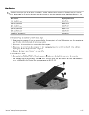
... (see "Battery" on , and then shut it up and to the left, and remove the cover. The hard drive cover is off or in Hibernation, turn the computer on page 4-7). Removal and replacement procedures 4-10 If you are also available in the Plastics Kit, spare part number 486621-001. The hard...
... (see "Battery" on , and then shut it up and to the left, and remove the cover. The hard drive cover is off or in Hibernation, turn the computer on page 4-7). Removal and replacement procedures 4-10 If you are also available in the Plastics Kit, spare part number 486621-001. The hard...
Service Guide
Page 53
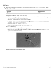
... from the clip built into the base enclosure. Remove the RTC battery: 1. Removal and replacement procedures 4-12 The RTC battery is off or in Hibernation, turn the computer on page 4-7). 5. Remove the hard drive cover (see "Battery" on , and then shut it uninstalled for 5 or more minutes causes all external devices...
... from the clip built into the base enclosure. Remove the RTC battery: 1. Removal and replacement procedures 4-12 The RTC battery is off or in Hibernation, turn the computer on page 4-7). 5. Remove the hard drive cover (see "Battery" on , and then shut it uninstalled for 5 or more minutes causes all external devices...
Service Guide
Page 54
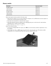
... in the Plastics Kit, spare part number 486621-001. Removal and replacement procedures 4-13 If you are unsure whether the computer is included in Hibernation, turn the computer on page 4-7). Memory module Description 512-MB, PC2-5300 1-GB, PC2-5300 2-GB, PC2-5300 512-MB, PC2-6400 1-GB, PC2-6400 2-GB...
... in the Plastics Kit, spare part number 486621-001. Removal and replacement procedures 4-13 If you are unsure whether the computer is included in Hibernation, turn the computer on page 4-7). Memory module Description 512-MB, PC2-5300 1-GB, PC2-5300 2-GB, PC2-5300 512-MB, PC2-6400 1-GB, PC2-6400 2-GB...
Service Guide
Page 56
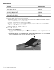
... 459263-002 482260-001 482260-002 Before removing the WLAN module, follow these steps: 1. If you are unsure whether the computer is included in Hibernation, turn the computer on page 4-7). Disconnect the power from the computer by first unplugging the power cord from the AC outlet and then unplugging the AC...
... 459263-002 482260-001 482260-002 Before removing the WLAN module, follow these steps: 1. If you are unsure whether the computer is included in Hibernation, turn the computer on page 4-7). Disconnect the power from the computer by first unplugging the power cord from the AC outlet and then unplugging the AC...
Service Guide
Page 59
... computer upside down, with the front toward you are unsure whether the computer is off or in Hibernation, turn the computer on page 4-7). If you . 2. Remove the keyboard: 1. Before removing the keyboard, follow these steps: 1. Disconnect all external devices connected to the computer. Shut ...
... computer upside down, with the front toward you are unsure whether the computer is off or in Hibernation, turn the computer on page 4-7). If you . 2. Remove the keyboard: 1. Before removing the keyboard, follow these steps: 1. Disconnect all external devices connected to the computer. Shut ...
Service Guide
Page 60
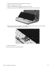
Turn the computer display-side up, with the front toward you. 4. Lift the rear edge of the keyboard. 6. Removal and replacement procedures 4-19 Release the zero insertion force (ZIF) connector 1 to install the keyboard. 3. Remove the keyboard. Reverse this procedure to which the keyboard cable is attached, and then disconnect the keyboard cable 2 from the system board. 8. Open the computer as far as possible. 5. Release the tabs 1 along the right and left edges of the keyboard 2, and then slide it back until it rests on the display. 7.
Turn the computer display-side up, with the front toward you. 4. Lift the rear edge of the keyboard. 6. Removal and replacement procedures 4-19 Release the zero insertion force (ZIF) connector 1 to install the keyboard. 3. Remove the keyboard. Reverse this procedure to which the keyboard cable is attached, and then disconnect the keyboard cable 2 from the system board. 8. Open the computer as far as possible. 5. Release the tabs 1 along the right and left edges of the keyboard 2, and then slide it back until it rests on the display. 7.
Service Guide
Page 61
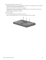
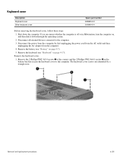
... Before removing the keyboard cover, follow these steps: 1. Remove the 2 Phillips PM2.5x9.0 screws 1 at the corners and the 2 Phillips PM2.0x4.0 screws 2 in Hibernation, turn the computer on, and then shut it down the computer. Remove the keyboard cover: 1. Remove the keyboard (see "Battery" on page 4-17). If you are...
... Before removing the keyboard cover, follow these steps: 1. Remove the 2 Phillips PM2.5x9.0 screws 1 at the corners and the 2 Phillips PM2.0x4.0 screws 2 in Hibernation, turn the computer on, and then shut it down the computer. Remove the keyboard cover: 1. Remove the keyboard (see "Battery" on page 4-17). If you are...
Service Guide
Page 62
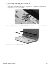
2. Slide the keyboard cover toward you. 3. Reverse this procedure to which the power button board cable is attached, and disconnect the power button board cable 2 from the top cover, and then lift up to remove the keyboard cover. Release the ZIF connector 1 to install the keyboard cover. Open the computer as far as possible. 4. Turn the computer display-side up, with the front toward the display panel until it disengages from the system board. 5. Removal and replacement procedures 4-21
2. Slide the keyboard cover toward you. 3. Reverse this procedure to which the power button board cable is attached, and disconnect the power button board cable 2 from the top cover, and then lift up to remove the keyboard cover. Release the ZIF connector 1 to install the keyboard cover. Open the computer as far as possible. 4. Turn the computer display-side up, with the front toward the display panel until it disengages from the system board. 5. Removal and replacement procedures 4-21
Service Guide
Page 63
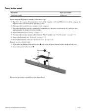
... to the computer. 3. Remove the keyboard cover (see "WLAN module" on page 4-15). 6. If you are unsure whether the computer is off or in Hibernation, turn the computer on page 4-20). Remove the power button board 2. Disconnect the wireless antenna cables from the computer. 4. Remove the power button board: 1.
... to the computer. 3. Remove the keyboard cover (see "WLAN module" on page 4-15). 6. If you are unsure whether the computer is off or in Hibernation, turn the computer on page 4-20). Remove the power button board 2. Disconnect the wireless antenna cables from the computer. 4. Remove the power button board: 1.
Service Guide
Page 65
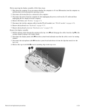
... it to the computer. 3. Remove the battery (see "Keyboard" on page 4-7). 5. Remove the display assembly: 1. Remove the caps lock LED 5 from the clip 2 in Hibernation, turn the computer on the top cover. Shut down through the opening in the top cover 1 and disengage the cables from its routing channel. 3. If you...
... it to the computer. 3. Remove the battery (see "Keyboard" on page 4-7). 5. Remove the display assembly: 1. Remove the caps lock LED 5 from the clip 2 in Hibernation, turn the computer on the top cover. Shut down through the opening in the top cover 1 and disengage the cables from its routing channel. 3. If you...


