Hardware Reference Guide
Page 1
Hardware Reference Guide HP EliteDesk 800 G1 Tower HP EliteDesk 800 G1 Small Form Factor HP EliteDesk 800 G1 Ultra-slim Desktop
Hardware Reference Guide HP EliteDesk 800 G1 Tower HP EliteDesk 800 G1 Small Form Factor HP EliteDesk 800 G1 Ultra-slim Desktop
Hardware Reference Guide
Page 2
... technical or editorial errors or omissions contained herein. No part of Microsoft Corporation. Hardware Reference Guide HP EliteDesk 800 G1 Tower HP EliteDesk 800 G1 Small Form Factor HP EliteDesk 800 G1 Ultra-slim Desktop First Edition (April 2013) Document part number: 719014-001 HP shall not be construed as constituting an additional warranty. © Copyright 2013 Hewlett-Packard Development Company...
... technical or editorial errors or omissions contained herein. No part of Microsoft Corporation. Hardware Reference Guide HP EliteDesk 800 G1 Tower HP EliteDesk 800 G1 Small Form Factor HP EliteDesk 800 G1 Ultra-slim Desktop First Edition (April 2013) Document part number: 719014-001 HP shall not be construed as constituting an additional warranty. © Copyright 2013 Hewlett-Packard Development Company...

Hardware Reference Guide
Page 5
...) front panel components 3 Small Form Factor (SFF) front panel components 4 Ultra-slim Desktop (USDT) front panel components 5 Tower (TWR) rear panel components 6 Small Form Factor (SFF) rear panel components 7 Ultra-slim Desktop (USDT) rear panel components 8 Media card ...reader components ...9 Keyboard ...10 Using the Windows logo key 10 Serial number location ...12 Tower (TWR) ...12 Small Form Factor (SFF 12 Ultra-slim Desktop (USDT 13 2 Tower (TWR) hardware upgrades ...14 Serviceability features ...14 Warnings and cautions ...14 Removing the computer access panel 15...
...) front panel components 3 Small Form Factor (SFF) front panel components 4 Ultra-slim Desktop (USDT) front panel components 5 Tower (TWR) rear panel components 6 Small Form Factor (SFF) rear panel components 7 Ultra-slim Desktop (USDT) rear panel components 8 Media card ...reader components ...9 Keyboard ...10 Using the Windows logo key 10 Serial number location ...12 Tower (TWR) ...12 Small Form Factor (SFF 12 Ultra-slim Desktop (USDT 13 2 Tower (TWR) hardware upgrades ...14 Serviceability features ...14 Warnings and cautions ...14 Removing the computer access panel 15...

Hardware Reference Guide
Page 6
...or 2.5-inch hard drive 44 Installing a 3.5-inch or 2.5-inch hard drive 45 Installing a security lock ...50 Cable lock ...50 Padlock ...50 HP business PC security lock 51 Front bezel security ...55 3 Small Form Factor (SFF) hardware upgrades 57 Serviceability features ...57 Warnings and cautions ...... access panel 59 Removing the front bezel ...60 Removing bezel blanks ...61 Replacing the front bezel ...62 Changing from desktop to tower configuration 63 System board connections ...64 Installing additional memory ...65 DIMMs ...65 DDR3-SDRAM DIMMs ...65 Populating DIMM sockets 65 Installing...
...or 2.5-inch hard drive 44 Installing a 3.5-inch or 2.5-inch hard drive 45 Installing a security lock ...50 Cable lock ...50 Padlock ...50 HP business PC security lock 51 Front bezel security ...55 3 Small Form Factor (SFF) hardware upgrades 57 Serviceability features ...57 Warnings and cautions ...... access panel 59 Removing the front bezel ...60 Removing bezel blanks ...61 Replacing the front bezel ...62 Changing from desktop to tower configuration 63 System board connections ...64 Installing additional memory ...65 DIMMs ...65 DDR3-SDRAM DIMMs ...65 Populating DIMM sockets 65 Installing...
Hardware Reference Guide
Page 7
... panel 101 Removing the front bezel ...102 Removing a bezel blank ...103 Replacing the front bezel ...104 Changing from desktop to tower configuration 105 System board connections ...106 Installing additional memory ...107 SODIMMs ...107 DDR3-SDRAM SODIMMs 107 Populating SODIMM sockets 108 Installing ...Replacing the hard drive ...114 Installing and removing a port cover 118 Installing a security lock ...119 Cable lock ...119 Padlock ...120 HP business PC security lock 120 Front bezel security ...124 Appendix A Battery replacement ...126 Appendix B Unlocking the Smart Cover Lock 129 Smart ...
... panel 101 Removing the front bezel ...102 Removing a bezel blank ...103 Replacing the front bezel ...104 Changing from desktop to tower configuration 105 System board connections ...106 Installing additional memory ...107 SODIMMs ...107 DDR3-SDRAM SODIMMs 107 Populating SODIMM sockets 108 Installing ...Replacing the hard drive ...114 Installing and removing a port cover 118 Installing a security lock ...119 Cable lock ...119 Padlock ...120 HP business PC security lock 120 Front bezel security ...124 Appendix A Battery replacement ...126 Appendix B Unlocking the Smart Cover Lock 129 Smart ...

Hardware Reference Guide
Page 9
For a complete listing of the hardware and software installed in a tower orientation or a desktop orientation. NOTE: All three computer models can be used in the computer, run the diagnostic utility (included on the model. 1 Product features Standard configuration features Features may vary depending on some computer models only). Tower (TWR) ENWW Standard configuration features 1
For a complete listing of the hardware and software installed in a tower orientation or a desktop orientation. NOTE: All three computer models can be used in the computer, run the diagnostic utility (included on the model. 1 Product features Standard configuration features Features may vary depending on some computer models only). Tower (TWR) ENWW Standard configuration features 1
Hardware Reference Guide
Page 11
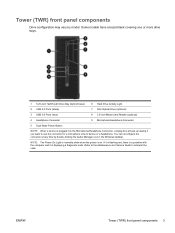
... normally white when the power is displaying a diagnostic code. If it is flashing red, there is a problem with the computer and it is on. ENWW Tower (TWR) front panel components 3 Some models have a bezel blank covering one or more drive bays. 1 5.25-inch Half-Height Drive Bay (behind bezel) 6 Hard ...the connector at any time by model. Refer to the Maintenance and Service Guide to use the connector for a microphone Line-In device or a headphone. Tower (TWR) front panel components Drive configuration may vary by double-clicking the Audio Manager icon in the Windows taskbar.
... normally white when the power is displaying a diagnostic code. If it is flashing red, there is a problem with the computer and it is on. ENWW Tower (TWR) front panel components 3 Some models have a bezel blank covering one or more drive bays. 1 5.25-inch Half-Height Drive Bay (behind bezel) 6 Hard ...the connector at any time by model. Refer to the Maintenance and Service Guide to use the connector for a microphone Line-In device or a headphone. Tower (TWR) front panel components Drive configuration may vary by double-clicking the Audio Manager icon in the Windows taskbar.
Hardware Reference Guide
Page 14
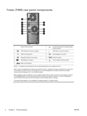
...In Audio Connector (blue) 6 USB 3.0 Ports (blue) NOTE: An optional second serial port and an optional parallel port are available from HP. You can be used at any time by doubleclicking the Audio Manager icon in one of the system board slots, the video connectors on... the graphics card and the integrated graphics on the system board may be disabled by changing settings in device or a microphone. Tower (TWR) rear panel components 1 Power Cord Connector 2 PS/2 Keyboard Connector (purple) 7 Line-Out Connector for such a configuration, only the display...
...In Audio Connector (blue) 6 USB 3.0 Ports (blue) NOTE: An optional second serial port and an optional parallel port are available from HP. You can be used at any time by doubleclicking the Audio Manager icon in one of the system board slots, the video connectors on... the graphics card and the integrated graphics on the system board may be disabled by changing settings in device or a microphone. Tower (TWR) rear panel components 1 Power Cord Connector 2 PS/2 Keyboard Connector (purple) 7 Line-Out Connector for such a configuration, only the display...

Hardware Reference Guide
Page 20
Tower (TWR) Small Form Factor (SFF) 12 Chapter 1 Product features ENWW Keep these numbers available for use when contacting customer service for assistance. Windows Logo Key + ...
Tower (TWR) Small Form Factor (SFF) 12 Chapter 1 Product features ENWW Keep these numbers available for use when contacting customer service for assistance. Windows Logo Key + ...

Hardware Reference Guide
Page 22
... damage to cool before touching. Do not disable the power cord grounding plug. This guide is easily accessible at http://www.hp.com/ergo. Disconnect power to upgrade and service. No tools are discharged of static electricity by briefly touching a grounded metal ... the enclosure before removing the enclosure. It describes proper workstation, setup, posture, and health and work habits for more information. 2 Tower (TWR) hardware upgrades Serviceability features The computer includes features that you are needed for most of the installation procedures described in a grounded...
... damage to cool before touching. Do not disable the power cord grounding plug. This guide is easily accessible at http://www.hp.com/ergo. Disconnect power to upgrade and service. No tools are discharged of static electricity by briefly touching a grounded metal ... the enclosure before removing the enclosure. It describes proper workstation, setup, posture, and health and work habits for more information. 2 Tower (TWR) hardware upgrades Serviceability features The computer includes features that you are needed for most of the installation procedures described in a grounded...

Hardware Reference Guide
Page 24
Replacing the computer access panel Slide the lip on the front end of the access panel under the lip on the front of the chassis (1) then press the back end of the access panel onto the unit so that it locks into place (2). 16 Chapter 2 Tower (TWR) hardware upgrades ENWW
Replacing the computer access panel Slide the lip on the front end of the access panel under the lip on the front of the chassis (1) then press the back end of the access panel onto the unit so that it locks into place (2). 16 Chapter 2 Tower (TWR) hardware upgrades ENWW

Hardware Reference Guide
Page 26
... some models, there are bezel blanks covering one or more drive bays that hold the bezel blank in place (1) then pull the bezel blank from HP) that surrounds the front of the drive. ● To remove a 3.5-inch bezel blank, press outward on the retaining tabs that need to remove it (2). 18...
... some models, there are bezel blanks covering one or more drive bays that hold the bezel blank in place (1) then pull the bezel blank from HP) that surrounds the front of the drive. ● To remove a 3.5-inch bezel blank, press outward on the retaining tabs that need to remove it (2). 18...
Hardware Reference Guide
Page 28
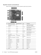
... Hard Drive Expansion Card Expansion Card Expansion Card Expansion Card Expansion Card Expansion Card Parallel Port Serial Port Hood Lock Hood Sensor Battery 20 Chapter 2 Tower (TWR) hardware upgrades ENWW
... Hard Drive Expansion Card Expansion Card Expansion Card Expansion Card Expansion Card Expansion Card Parallel Port Serial Port Hood Lock Hood Sensor Battery 20 Chapter 2 Tower (TWR) hardware upgrades ENWW

Hardware Reference Guide
Page 30
..., with one 2-GB DIMM, and three 1-GB DIMMs, Channel A should be assigned to the total memory capacity of the DIMMs in the system. 22 Chapter 2 Tower (TWR) hardware upgrades ENWW Sockets DIMM3 and DIMM4 operate in memory channel B. DIMMs constructed with x8 and x16 DDR devices; In addition, the computer supports...
..., with one 2-GB DIMM, and three 1-GB DIMMs, Channel A should be assigned to the total memory capacity of the DIMMs in the system. 22 Chapter 2 Tower (TWR) hardware upgrades ENWW Sockets DIMM3 and DIMM4 operate in memory channel B. DIMMs constructed with x8 and x16 DDR devices; In addition, the computer supports...

Hardware Reference Guide
Page 32
... devices that the memory capacity is fully inserted and properly seated. 6. Match the notch on the module with the tab on the computer. 24 Chapter 2 Tower (TWR) hardware upgrades ENWW Reconnect the power cord and turn on the memory socket.
... devices that the memory capacity is fully inserted and properly seated. 6. Match the notch on the module with the tab on the computer. 24 Chapter 2 Tower (TWR) hardware upgrades ENWW Reconnect the power cord and turn on the memory socket.

Hardware Reference Guide
Page 34
... rock it . NOTE: Before removing an installed expansion card, disconnect any cables that may be attached to scrape the card against other components. 26 Chapter 2 Tower (TWR) hardware upgrades ENWW b. Lift the card straight up to remove it back and forth until the connectors pull free from the expansion slot. Lift...
... rock it . NOTE: Before removing an installed expansion card, disconnect any cables that may be attached to scrape the card against other components. 26 Chapter 2 Tower (TWR) hardware upgrades ENWW b. Lift the card straight up to remove it back and forth until the connectors pull free from the expansion slot. Lift...

Hardware Reference Guide
Page 36
Replace the computer access panel. 15. Reconfigure the computer, if necessary. 28 Chapter 2 Tower (TWR) hardware upgrades ENWW Connect internal cables to the installed card, if needed . 14. Reconnect the power cord and turn on the computer. 16. Lock any security devices that it snaps firmly into place. 13. Close the expansion card retention latch, making sure that were disengaged when the computer access panel was removed. 17. Connect external cables to the system board, if needed . 12.
Replace the computer access panel. 15. Reconfigure the computer, if necessary. 28 Chapter 2 Tower (TWR) hardware upgrades ENWW Connect internal cables to the installed card, if needed . 14. Reconnect the power cord and turn on the computer. 16. Lock any security devices that it snaps firmly into place. 13. Close the expansion card retention latch, making sure that were disengaged when the computer access panel was removed. 17. Connect external cables to the system board, if needed . 12.

Hardware Reference Guide
Page 38
...Screws 2 Silver and Blue 6-32 Isolation Mounting Screws Device USB 3.0 Media Card Reader Secondary Hard Drive in the 3.5-inch optional drive bay. HP has provided extra guide screws (four 6-32 silver and blue isolation mounting guide screws and four silver 6-32 standard guide screws) installed on ... system board labeled MEDIA3.0. ● The power cable for a USB 3.0 media card reader installed in 3.5-inch Hard Drive Bay 30 Chapter 2 Tower (TWR) hardware upgrades ENWW The second branch is a three-headed cable with the first connector routed to the bottom 2.5-inch hard drive bay, the...
...Screws 2 Silver and Blue 6-32 Isolation Mounting Screws Device USB 3.0 Media Card Reader Secondary Hard Drive in the 3.5-inch optional drive bay. HP has provided extra guide screws (four 6-32 silver and blue isolation mounting guide screws and four silver 6-32 standard guide screws) installed on ... system board labeled MEDIA3.0. ● The power cable for a USB 3.0 media card reader installed in 3.5-inch Hard Drive Bay 30 Chapter 2 Tower (TWR) hardware upgrades ENWW The second branch is a three-headed cable with the first connector routed to the bottom 2.5-inch hard drive bay, the...

Hardware Reference Guide
Page 40
... by the user or third-party vendor. You must disconnect the power cord to avoid damage to avoid damaging the cable. 32 Chapter 2 Tower (TWR) hardware upgrades ENWW Turn off the computer properly through the operating system, then turn off any security devices that prohibit opening the computer...from the back of a drive before removing the drive from the power outlet and disconnect any external devices. Removing a 5.25-inch drive NOTE: HP does not offer a 5.25-inch optical drive for this computer model. CAUTION: All removable media should be taken out of the drive. Disconnect ...
... by the user or third-party vendor. You must disconnect the power cord to avoid damage to avoid damaging the cable. 32 Chapter 2 Tower (TWR) hardware upgrades ENWW Turn off the computer properly through the operating system, then turn off any security devices that prohibit opening the computer...from the back of a drive before removing the drive from the power outlet and disconnect any external devices. Removing a 5.25-inch drive NOTE: HP does not offer a 5.25-inch optical drive for this computer model. CAUTION: All removable media should be taken out of the drive. Disconnect ...

Hardware Reference Guide
Page 42
CAUTION: Use only 5-mm long screws as guide screws. If you are installing an optical drive, install four M3 metric guide screws (not provided) in the lower holes on each side of the drive. 8. Longer screws can damage the internal components of the drive. NOTE: When replacing an optical drive, transfer the four M3 metric guide screws from the old drive to align the guide screws with the guide slots, until the drive snaps into the drive bay, making sure to the new one. Slide the drive into place. 34 Chapter 2 Tower (TWR) hardware upgrades ENWW 7.
CAUTION: Use only 5-mm long screws as guide screws. If you are installing an optical drive, install four M3 metric guide screws (not provided) in the lower holes on each side of the drive. 8. Longer screws can damage the internal components of the drive. NOTE: When replacing an optical drive, transfer the four M3 metric guide screws from the old drive to align the guide screws with the guide slots, until the drive snaps into the drive bay, making sure to the new one. Slide the drive into place. 34 Chapter 2 Tower (TWR) hardware upgrades ENWW 7.


