
Getting Started Guide
Page 6
... the software ...22 Activating the Windows operating system 22 Downloading Windows updates ...22 Customizing the monitor display ...22 Turning off the computer ...23 If you encounter issues ...23 Performing basic troubleshooting ...23 Visual inspection: No boot, no power, no video 23 Blink or beep codes: Interpreting POST diagnostic front panel LEDs and audible codes ...24 HP Support Assistant ...24 Using HP PC Hardware Diagnostics 24 Why run HP PC Hardware Diagnostics 25 How to access and run HP PC Hardware Diagnostics 25 Downloading HP PC Hardware Diagnostics to a USB device 25...
... the software ...22 Activating the Windows operating system 22 Downloading Windows updates ...22 Customizing the monitor display ...22 Turning off the computer ...23 If you encounter issues ...23 Performing basic troubleshooting ...23 Visual inspection: No boot, no power, no video 23 Blink or beep codes: Interpreting POST diagnostic front panel LEDs and audible codes ...24 HP Support Assistant ...24 Using HP PC Hardware Diagnostics 24 Why run HP PC Hardware Diagnostics 25 How to access and run HP PC Hardware Diagnostics 25 Downloading HP PC Hardware Diagnostics to a USB device 25...

Getting Started Guide
Page 11
... need a driver for your desktop. Blink or beep codes: Interpreting POST diagnostic front panel LEDs and audible codes If you see the following list of general suggestions before turning it is supported on the system. ● If the system has multiple video sources (embedded, PCI, or PCI-Express adapters) installed (embedded video on the front of your computer after installing a non-Plug and Play expansion board or other video ports are disabled; Using HP PC Hardware Diagnostics If HP Support Assistant...
... need a driver for your desktop. Blink or beep codes: Interpreting POST diagnostic front panel LEDs and audible codes If you see the following list of general suggestions before turning it is supported on the system. ● If the system has multiple video sources (embedded, PCI, or PCI-Express adapters) installed (embedded video on the front of your computer after installing a non-Plug and Play expansion board or other video ports are disabled; Using HP PC Hardware Diagnostics If HP Support Assistant...

Getting Started Guide
Page 17
... a backup using Windows Backup and Restore: NOTE: The backup process may be sure to create system recovery DVDs or USB flash drive, you use System Restore to return the computer to http://www.hp.com/support, select your hard drive. Close all user information. Click System protection, click System Restore, click Next, and then follow the on -screen instructions to set from a recovery image stored on the computer at the factory. However...
... a backup using Windows Backup and Restore: NOTE: The backup process may be sure to create system recovery DVDs or USB flash drive, you use System Restore to return the computer to http://www.hp.com/support, select your hard drive. Close all user information. Click System protection, click System Restore, click Next, and then follow the on -screen instructions to set from a recovery image stored on the computer at the factory. However...
Getting Started Guide
Page 23
... set in diagnostics, and guided assistance. If the system has multiple video sources (embedded, PCI, or PCI-Express adapters) installed (embedded video on some models only) and a single monitor, the monitor must be sure that HP includes on all the needed device drivers have installed an operating system other software components. ● Failure ID: When a failure is supported on the front of diagnosing hardware issues and expedite the support process when issues are disabled; Blink or beep codes...
... set in diagnostics, and guided assistance. If the system has multiple video sources (embedded, PCI, or PCI-Express adapters) installed (embedded video on some models only) and a single monitor, the monitor must be sure that HP includes on all the needed device drivers have installed an operating system other software components. ● Failure ID: When a failure is supported on the front of diagnosing hardware issues and expedite the support process when issues are disabled; Blink or beep codes...
Getting Started Guide
Page 25
... time troubleshooting the problem with a different cable to the network. ● Check the power LED on the front of the computer to the Maintenance and Service Guide (English only) for details. ● If the screen is blank, plug the monitor into the operating system, use one is available, or replace the monitor with a monitor that was recently installed. ◦ Write down the product ID number, computer and monitor serial numbers, and the failure...
... time troubleshooting the problem with a different cable to the network. ● Check the power LED on the front of the computer to the Maintenance and Service Guide (English only) for details. ● If the screen is blank, plug the monitor into the operating system, use one is available, or replace the monitor with a monitor that was recently installed. ◦ Write down the product ID number, computer and monitor serial numbers, and the failure...

Getting Started Guide
Page 32
... access HP Support Assistant in Windows 10, type support in Windows 10 During boot, the other video ports are using a printer, you need a driver for your PC Using HP Support Assistant, from the system before turning it on all HP or Compaq computers running Windows 10. For example, if you are disabled, if the monitor is connected to one location you hear beeps, see flashing LEDs on the front of your computer after installing a non-Plug and Play expansion board...
... access HP Support Assistant in Windows 10, type support in Windows 10 During boot, the other video ports are using a printer, you need a driver for your PC Using HP Support Assistant, from the system before turning it on all HP or Compaq computers running Windows 10. For example, if you are disabled, if the monitor is connected to one location you hear beeps, see flashing LEDs on the front of your computer after installing a non-Plug and Play expansion board...

Hardware Reference Guide
Page 9
... system board slots, the video connectors on the graphics card and the integrated graphics on the PS/2 connectors if enabled in the Windows taskbar. Rear panel components 1 PS/2 Mouse Connector (green) 7 PS/2 Keyboard Connector (purple) 2 Serial Connector 3 RJ-45 Network Connector 8 DisplayPort Monitor Connectors 9 VGA Monitor Connector 4 USB 2.0 Ports with the wake from S4/S5 feature. However, for such a configuration, only the display connected to use the connector for powered audio devices (green) NOTE: An optional second serial port and an optional parallel port...
... system board slots, the video connectors on the graphics card and the integrated graphics on the PS/2 connectors if enabled in the Windows taskbar. Rear panel components 1 PS/2 Mouse Connector (green) 7 PS/2 Keyboard Connector (purple) 2 Serial Connector 3 RJ-45 Network Connector 8 DisplayPort Monitor Connectors 9 VGA Monitor Connector 4 USB 2.0 Ports with the wake from S4/S5 feature. However, for such a configuration, only the display connected to use the connector for powered audio devices (green) NOTE: An optional second serial port and an optional parallel port...

Maintenance and Service Guide
Page 13
... configuration, only the display connected to use the connector for powered audio devices (green) NOTE: An optional second serial port and an optional parallel port are available from HP. Rear panel components 3 You can be used at any time by changing settings in Computer Setup. The wake from S4 feature is installed in device or a microphone. Rear panel components 1 PS/2 Mouse Connector (green) 7 PS/2 Keyboard Connector (purple) 2 Serial Connector 3 RJ-45 Network Connector 8 DisplayPort Monitor Connectors 9 VGA Monitor Connector 4 USB 2.0 Ports with the wake...
... configuration, only the display connected to use the connector for powered audio devices (green) NOTE: An optional second serial port and an optional parallel port are available from HP. Rear panel components 3 You can be used at any time by changing settings in Computer Setup. The wake from S4 feature is installed in device or a microphone. Rear panel components 1 PS/2 Mouse Connector (green) 7 PS/2 Keyboard Connector (purple) 2 Serial Connector 3 RJ-45 Network Connector 8 DisplayPort Monitor Connectors 9 VGA Monitor Connector 4 USB 2.0 Ports with the wake...

Maintenance and Service Guide
Page 80
... Esc (to factory defaults Default is '6.0 Gbps'. Reset Security Boot keys to access the boot menu) and then F9 (Boot Order), or only F9 (skipping the boot menu) when the monitor light turns green. The default is disabled. The default is disabled. Default is restored, if it , making Windows resistant to malicious modification from the selected non-default device for this option to: ● Power off-causes the computer to legacy devices, and so on. Setting this one time...
... Esc (to factory defaults Default is '6.0 Gbps'. Reset Security Boot keys to access the boot menu) and then F9 (Boot Order), or only F9 (skipping the boot menu) when the monitor light turns green. The default is disabled. The default is disabled. Default is restored, if it , making Windows resistant to malicious modification from the selected non-default device for this option to: ● Power off-causes the computer to legacy devices, and so on. Setting this one time...

Maintenance and Service Guide
Page 87
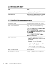
... incorrect. To access Control Panel in Windows 10, type control panel in Windows 7, select Start, and then select Control Panel. The Num Lock light must manually disable the Smart Cover lock . There is no sound or sound volume is turned on the keypad. Cause System volume may need to be set correctly. 3. Check the Computer Setup settings to use the arrow keys on . Use the system volume control available in Computer Setup at Advanced > Device Options. In case of applications...
... incorrect. To access Control Panel in Windows 10, type control panel in Windows 7, select Start, and then select Control Panel. The Num Lock light must manually disable the Smart Cover lock . There is no sound or sound volume is turned on the keypad. Cause System volume may need to be set correctly. 3. Check the Computer Setup settings to use the arrow keys on . Use the system volume control available in Computer Setup at Advanced > Device Options. In case of applications...
Maintenance and Service Guide
Page 105
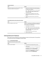
...Windows 8.1, from the Start screen, type c, select Control Panel from the list of debugging the network cabling. Run Computer Setup and enable network controller. 2. Review the documentation that came with HP memory. 4. Cause Network controller is bad. Solving Network Problems 95 Table 6-2 Solving Network Problems Network driver does not detect network controller. Solution CAUTION: To avoid damage to the DIMMs or the system board, you still cannot resolve the issue, contact Customer Support. Beeps and flashing LEDs are codes for network problems are using Device Manager...
...Windows 8.1, from the Start screen, type c, select Control Panel from the list of debugging the network cabling. Run Computer Setup and enable network controller. 2. Review the documentation that came with HP memory. 4. Cause Network controller is bad. Solving Network Problems 95 Table 6-2 Solving Network Problems Network driver does not detect network controller. Solution CAUTION: To avoid damage to the DIMMs or the system board, you still cannot resolve the issue, contact Customer Support. Beeps and flashing LEDs are codes for network problems are using Device Manager...
Maintenance and Service Guide
Page 106
...from the Start screen, type c, select Control Panel from the list of applications, and then select Device Manager. Enable the network controller in the taskbar search box, and then select Device Manager from the list of applications. To access Device Manager in Windows 10, type device manager in the operating system using Device Manager. Reinstall network drivers. Network controller is not set up properly. Disable auto-sensing capabilities and force the system into the correct operating mode. 96 Chapter 6 Troubleshooting without diagnostics Table 6-2 Solving Network Problems...
...from the Start screen, type c, select Control Panel from the list of applications, and then select Device Manager. Enable the network controller in the taskbar search box, and then select Device Manager from the list of applications. To access Device Manager in Windows 10, type device manager in the operating system using Device Manager. Reinstall network drivers. Network controller is not set up properly. Disable auto-sensing capabilities and force the system into the correct operating mode. 96 Chapter 6 Troubleshooting without diagnostics Table 6-2 Solving Network Problems...
Maintenance and Service Guide
Page 113
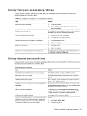
... UTP cable is not set up to the Internet. IP address is not working. 1. Click Internet Options. The device does not have power. Verify that the Web browser is useful for having the browser remember some specific information that the USB ports are disabled in . Windows 7: 1. The device is not configured properly. USB ports on .) Contact your ISP for the device. 2. Run the Computer Setup utility and ensure that the Web server can...
... UTP cable is not set up to the Internet. IP address is not working. 1. Click Internet Options. The device does not have power. Verify that the Web browser is useful for having the browser remember some specific information that the USB ports are disabled in . Windows 7: 1. The device is not configured properly. USB ports on .) Contact your ISP for the device. 2. Run the Computer Setup utility and ensure that the Web server can...
Maintenance and Service Guide
Page 116
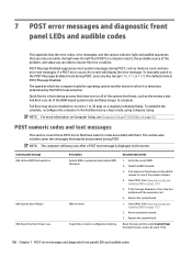
... may be used). Remove expansion boards. 3. Invalid time or date in configuration memory. To manually switch to see Computer Setup (F10) Utility on a regularly scheduled basis. Clear CMOS. (See Password security and resetting CMOS on Computer Setup, see if the problem remains. 4. Recommended action 1. Quick Boot is POST Message Disabled. POST Message Disabled suppresses most system messages during POST. 7 POST error messages and diagnostic front panel LEDs and audible codes This appendix lists the error codes, error messages...
... may be used). Remove expansion boards. 3. Invalid time or date in configuration memory. To manually switch to see Computer Setup (F10) Utility on a regularly scheduled basis. Clear CMOS. (See Password security and resetting CMOS on Computer Setup, see if the problem remains. 4. Recommended action 1. Quick Boot is POST Message Disabled. POST Message Disabled suppresses most system messages during POST. 7 POST error messages and diagnostic front panel LEDs and audible codes This appendix lists the error codes, error messages...
Maintenance and Service Guide
Page 117
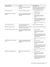
... changed , unplug the computer, restore the original memory configuration, and reboot the computer. 4. If the error persists, replace the system board. 1. Reboot the computer. 2. If the error persists, replace the system board. 1. Front audio cable has been detached or unseated from system board. Memory error during POST execution of the Management Engine (ME) BIOS Extensions option ROM. See the Removal and Replacement section for instructions on installing a new battery. 1. Upgrade BIOS to be replaced. Reconnect or replace front audio cable. Reboot the computer. 2. Control panel...
... changed , unplug the computer, restore the original memory configuration, and reboot the computer. 4. If the error persists, replace the system board. 1. Reboot the computer. 2. If the error persists, replace the system board. 1. Front audio cable has been detached or unseated from system board. Memory error during POST execution of the Management Engine (ME) BIOS Extensions option ROM. See the Removal and Replacement section for instructions on installing a new battery. 1. Upgrade BIOS to be replaced. Reconnect or replace front audio cable. Reboot the computer. 2. Control panel...

Maintenance and Service Guide
Page 120
... the keys are depressed. 3. Reconnect the keyboard with computer turned off . 2. Replace CPU fan. 901-Chassis, Rear Chassis, or Front Chassis Fan Chassis, rear chassis, or front chassis fan is an incompatibility or problem with this system 43A-USB Type-C I2C Not Connected Cable is installed. For one device, use SATA 0, SATA 1, and SATA 2. 110 Chapter 7 POST error messages and diagnostic front panel LEDs and audible codes Try rebooting the system. For optimal performance, replace the battery. 70x-Wireless Mode Not Supported...
... the keys are depressed. 3. Reconnect the keyboard with computer turned off . 2. Replace CPU fan. 901-Chassis, Rear Chassis, or Front Chassis Fan Chassis, rear chassis, or front chassis fan is an incompatibility or problem with this system 43A-USB Type-C I2C Not Connected Cable is installed. For one device, use SATA 0, SATA 1, and SATA 2. 110 Chapter 7 POST error messages and diagnostic front panel LEDs and audible codes Try rebooting the system. For optimal performance, replace the battery. 70x-Wireless Mode Not Supported...
Maintenance and Service Guide
Page 126
The CMOS button will not clear CMOS if the power cord is easily done through Computer Setup. Reconnect the external devices. 7. Use Computer Setup to factory defaults. For instructions on Computer Setup, see the system board components image at System board on page 63. 116 Chapter 8 Password security and resetting CMOS NOTE: For assistance locating the CMOS button and other system board components, see Computer Setup (F10) Utility on page 60. 5. NOTE: Make sure you that configuration changes have disconnected...
The CMOS button will not clear CMOS if the power cord is easily done through Computer Setup. Reconnect the external devices. 7. Use Computer Setup to factory defaults. For instructions on Computer Setup, see the system board components image at System board on page 63. 116 Chapter 8 Password security and resetting CMOS NOTE: For assistance locating the CMOS button and other system board components, see Computer Setup (F10) Utility on page 60. 5. NOTE: Make sure you that configuration changes have disconnected...
Maintenance and Service Guide
Page 139
... installed on the computer at the factory. NOTE: Always use this procedure. Click the Start button, right-click Computer, and then click Properties. 3. See System Recovery using recovery media (select models only) on page 129. If you can order a recovery disc set up any software that you were not able to perform a System Recovery: ● Recovery image - System Recovery completely erases and reformats the hard disk drive, deleting all user information. 1. To start...
... installed on the computer at the factory. NOTE: Always use this procedure. Click the Start button, right-click Computer, and then click Properties. 3. See System Recovery using recovery media (select models only) on page 129. If you can order a recovery disc set up any software that you were not able to perform a System Recovery: ● Recovery image - System Recovery completely erases and reformats the hard disk drive, deleting all user information. 1. To start...

Maintenance and Service Guide
Page 151
... cleaning computer 14 mouse 15 safety precautions 14 CMOS backing up 113 clearing and resetting 115 computer specifications 140 computer cleaning 14 Computer Setup access problem 76 country power cord set requirements 137 Customer Support 74 D deleting a Power-On password 115 deleting a Setup password 115 DIMMs. See memory disassembly preparation 19 drive power cable removal and replacement 46 Driver Recovery DVD, creating 127 using for restore 131 Driver Recovery media, Windows 125 Driver Recovery media, Windows 8.1 125 drives cable connections 32 installation 32 locations 32 E electrostatic...
... cleaning computer 14 mouse 15 safety precautions 14 CMOS backing up 113 clearing and resetting 115 computer specifications 140 computer cleaning 14 Computer Setup access problem 76 country power cord set requirements 137 Customer Support 74 D deleting a Power-On password 115 deleting a Setup password 115 DIMMs. See memory disassembly preparation 19 drive power cable removal and replacement 46 Driver Recovery DVD, creating 127 using for restore 131 Driver Recovery media, Windows 125 Driver Recovery media, Windows 8.1 125 drives cable connections 32 installation 32 locations 32 E electrostatic...

Maintenance and Service Guide
Page 152
... Setup 76 flash drive 102 front panel 103 general 76 hard drive 81 hardware installation 94 Internet access 103 keyboard 92 Media Card Reader 83 memory 98 monitor 84 mouse 92 network 95 power 80 printer 91 software 105 processor removal and replacement 56 processors illustrated 6 product ID location 4 R rear baffle illustrated 7 rear panel components 3 recovery discs, steps for creating Windows 7 127 recovery discs, using for restore 131 recovery media, creating 127 recovery media, creating Windows 7 126 recovery partition, Windows 8 124 recovery partition, Windows 8.1 124 recovery USB flash...
... Setup 76 flash drive 102 front panel 103 general 76 hard drive 81 hardware installation 94 Internet access 103 keyboard 92 Media Card Reader 83 memory 98 monitor 84 mouse 92 network 95 power 80 printer 91 software 105 processor removal and replacement 56 processors illustrated 6 product ID location 4 R rear baffle illustrated 7 rear panel components 3 recovery discs, steps for creating Windows 7 127 recovery discs, using for restore 131 recovery media, creating 127 recovery media, creating Windows 7 126 recovery partition, Windows 8 124 recovery partition, Windows 8.1 124 recovery USB flash...


