Service Manual
Page 9
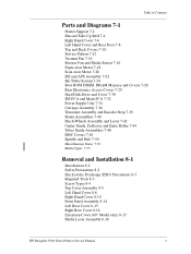
... 7-22 Ink Tubes System 7-24 Boot ROM DIMM, DRAM Memory and Covers 7-26 Rear Electronics Access Covers 7-28 Hard Disk Drive and Cover 7-30 ISS PCA and Main PCA 7-32 Power Supply Unit 7-34 Carriage Assembly 7-36 Tensioner Assembly and...Removal and Installation 8-1 Introduction 8-2 Safety Precautions 8-2 Electrostatic Discharge (ESD) Precautions 8-3 Required Tools 8-3 Screw Types 8-4 Top Cover Assembly 8-5 Left Hand Cover 8-6 Right Hand Cover 8-10 Front Panel Assembly 8-14 Left Rear Cover 8-15 Right Rear Cover 8-16 Extension Cover (60" Model only) 8-17 Media Lever Assembly 8-18 HP DesignJet 5000...
... 7-22 Ink Tubes System 7-24 Boot ROM DIMM, DRAM Memory and Covers 7-26 Rear Electronics Access Covers 7-28 Hard Disk Drive and Cover 7-30 ISS PCA and Main PCA 7-32 Power Supply Unit 7-34 Carriage Assembly 7-36 Tensioner Assembly and...Removal and Installation 8-1 Introduction 8-2 Safety Precautions 8-2 Electrostatic Discharge (ESD) Precautions 8-3 Required Tools 8-3 Screw Types 8-4 Top Cover Assembly 8-5 Left Hand Cover 8-6 Right Hand Cover 8-10 Front Panel Assembly 8-14 Left Rear Cover 8-15 Right Rear Cover 8-16 Extension Cover (60" Model only) 8-17 Media Lever Assembly 8-18 HP DesignJet 5000...
Service Manual
Page 58
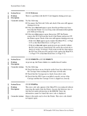
... 42 inches. n If the error does appear again, then power OFF the Printer, remove the I /O card also fails, replace the Main PCA ( ⇒ Page 8-79) or the Hard Disk Drive (⇒ Page 8-72). This error code should not appear again. 2-6 HP DesignJet 5000 Series Printers Service Manual If it works. If the new I /O Card from reaching...
... 42 inches. n If the error does appear again, then power OFF the Printer, remove the I /O card also fails, replace the Main PCA ( ⇒ Page 8-79) or the Hard Disk Drive (⇒ Page 8-72). This error code should not appear again. 2-6 HP DesignJet 5000 Series Printers Service Manual If it works. If the new I /O Card from reaching...
Service Manual
Page 75
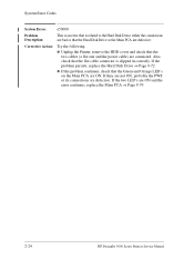
...Action: Try the following : n Unplug the Printer, remove the HDD cover and check that the two cables (a flat one and the power cable) are connected. Corrective Action: Try the following : n This error is sporadic and very rare; HP DesignJet 5000 Series Printers Service Manual 2-23 System Error: 1f500XX (...to A.02.xx in correctly. Even if the error appears again, there is very slow. If the problem persists, replace the Hard Disk Drive ⇒ Page 8-72. If the two LED's are defective. The Parallel Port setting in the PC BIOS should decrease the ...
...Action: Try the following : n Unplug the Printer, remove the HDD cover and check that the two cables (a flat one and the power cable) are connected. Corrective Action: Try the following : n This error is sporadic and very rare; HP DesignJet 5000 Series Printers Service Manual 2-23 System Error: 1f500XX (...to A.02.xx in correctly. Even if the error appears again, there is very slow. If the problem persists, replace the Hard Disk Drive ⇒ Page 8-72. If the two LED's are defective. The Parallel Port setting in the PC BIOS should decrease the ...
Service Manual
Page 76
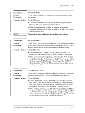
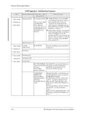
...This is an error that is clipped in correctly. Also check that the flat cable connector is related to the Hard Disk Drive, either the connections are bad or that the Hard Disk Drive or the Main PCA are defective. If the two LED's are defective. n If the problem continues, check that... Unplug the Printer, remove the HDD cover and check that the Green and Orange LED's on the Main PCA are connected. If they are not ON, probably the PWS or its connections are ON and the error continues, replace the Main PCA ⇒ Page 8-79. 2-24 HP DesignJet 5000 Series Printers Service Manual
...This is an error that is clipped in correctly. Also check that the flat cable connector is related to the Hard Disk Drive, either the connections are bad or that the Hard Disk Drive or the Main PCA are defective. If the two LED's are defective. n If the problem continues, check that... Unplug the Printer, remove the HDD cover and check that the Green and Orange LED's on the Main PCA are connected. If they are not ON, probably the PWS or its connections are ON and the error continues, replace the Main PCA ⇒ Page 8-79. 2-24 HP DesignJet 5000 Series Printers Service Manual
Service Manual
Page 100
...: You are defective. C6091A and C6096A - Also check that the Green and Orange LED's on the Back Cover): Make sure RTL Hard Disk Drives and Firmware are ON and the error continues, replace the Main PCA ⇒ Page 8-79. Quality Productivity Max. C6090A and C6095A ... Quality Productivity Max. Spinning up disk Boot Failed:1f500XX n Unplug the Printer, remove the HDD cover and check that the two cables (a This is clipped in correctly. For Part Numbers see Page 7-1. 4-4 HP DesignJet 5000 Series Printers Service Manual If the two LED's are used . Quality Productivity Max....
...: You are defective. C6091A and C6096A - Also check that the Green and Orange LED's on the Back Cover): Make sure RTL Hard Disk Drives and Firmware are ON and the error continues, replace the Main PCA ⇒ Page 8-79. Quality Productivity Max. C6090A and C6095A ... Quality Productivity Max. Spinning up disk Boot Failed:1f500XX n Unplug the Printer, remove the HDD cover and check that the two cables (a This is clipped in correctly. For Part Numbers see Page 7-1. 4-4 HP DesignJet 5000 Series Printers Service Manual If the two LED's are used . Quality Productivity Max....
Service Manual
Page 251
Removal and Installation 8 Screw Types 8-4 Top Cover Assembly 8-5 Left Hand Cover 8-6 Right Hand Cover 8-...58 Ink Supply Station (ISS) 8-62 Air Pressurization System (APS) 8-65 Service Station Assembly 8-67 Drop Detector Assembly 8-70 Hard Disk Drive (HDD) 8-72 LAN Card 8-74 Memory and BootROM DIMM's 8-75 Electronics Module Cover 8-77 Main PCA 8-79 Power Supply ... Booster Fan 8-103 Media Sensor 8-104 Entry Roller 8-106 Center Guide Assembly 8-107 Drive Roller Gear 8-109 Front Platen Assembly 8-110 Center Platen Assembly 8-112 Deflectors 8-114 HP DesignJet 5000 Series Printers Service Manual 8-1
Removal and Installation 8 Screw Types 8-4 Top Cover Assembly 8-5 Left Hand Cover 8-6 Right Hand Cover 8-...58 Ink Supply Station (ISS) 8-62 Air Pressurization System (APS) 8-65 Service Station Assembly 8-67 Drop Detector Assembly 8-70 Hard Disk Drive (HDD) 8-72 LAN Card 8-74 Memory and BootROM DIMM's 8-75 Electronics Module Cover 8-77 Main PCA 8-79 Power Supply ... Booster Fan 8-103 Media Sensor 8-104 Entry Roller 8-106 Center Guide Assembly 8-107 Drive Roller Gear 8-109 Front Platen Assembly 8-110 Center Platen Assembly 8-112 Deflectors 8-114 HP DesignJet 5000 Series Printers Service Manual 8-1
Service Manual
Page 322
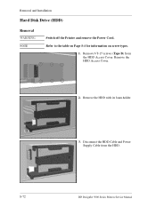
Remove the HDD with its foam holder. 3. Disconnect the HDD Cable and Power Supply Cable from the HDD Access Cover. Refer to the table on Page 8-4 for information on screw types. 1. Removal and Installation Hard Disk Drive (HDD) Removal WARNING NOTE Switch off the Printer and remove the Power Cord. Remove 6 T-15 screws (Type B) from the HDD. 8-72 HP DesignJet 5000 Series Printers Service Manual Remove the HDD Access Cover. 2.
Remove the HDD with its foam holder. 3. Disconnect the HDD Cable and Power Supply Cable from the HDD Access Cover. Refer to the table on Page 8-4 for information on screw types. 1. Removal and Installation Hard Disk Drive (HDD) Removal WARNING NOTE Switch off the Printer and remove the Power Cord. Remove 6 T-15 screws (Type B) from the HDD. 8-72 HP DesignJet 5000 Series Printers Service Manual Remove the HDD Access Cover. 2.
Service Manual
Page 323
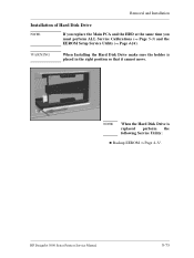
WARNING When Installing the Hard Disk Drive make sure the holder is replaced perform the following Service Utility: n Backup EEROM ⇒ Page 4-31. NOTE When the Hard Disk Drive is placed in the right position so that it cannot move. Removal and Installation Installation of Hard Disk Drive NOTE If you replace the Main PCA and the HDD at the same time you must perform ALL Service Calibrations (⇒ Page 5-3) and the EEROM Setup Service Utility (⇒ Page 4-24). HP DesignJet 5000 Series Printers Service Manual 8-73
WARNING When Installing the Hard Disk Drive make sure the holder is replaced perform the following Service Utility: n Backup EEROM ⇒ Page 4-31. NOTE When the Hard Disk Drive is placed in the right position so that it cannot move. Removal and Installation Installation of Hard Disk Drive NOTE If you replace the Main PCA and the HDD at the same time you must perform ALL Service Calibrations (⇒ Page 5-3) and the EEROM Setup Service Utility (⇒ Page 4-24). HP DesignJet 5000 Series Printers Service Manual 8-73

Service Manual
Page 329
... Cover - Refer to Page 8-74. 2. Disconnect and remove the Hard Disk Drive for information on Page 8-4 for safety reasons - Remove ALL BootROM/Memory DIMM's - Removal and Installation Main PCA Removal WARNING NOTE Switch off the Printer and remove the Power Cord. Refer to Page 8-16. 4. Refer to Page 8-77. 5. HP DesignJet 5000 Series Printers Service Manual 8-79 Refer to Page...
... Cover - Refer to Page 8-74. 2. Disconnect and remove the Hard Disk Drive for information on Page 8-4 for safety reasons - Remove ALL BootROM/Memory DIMM's - Removal and Installation Main PCA Removal WARNING NOTE Switch off the Printer and remove the Power Cord. Refer to Page 8-16. 4. Refer to Page 8-77. 5. HP DesignJet 5000 Series Printers Service Manual 8-79 Refer to Page...

Service Manual
Page 333
... to Page 8-16. 4. Refer to Page 8-15. 3. Disconnect and remove the Hard Disk Drive for information on Page 8-4 for safety reasons - Disconnect the PCA Power Supply connector from the Main PCA. Remove the Electronics Module Cover - HP DesignJet 5000 Series Printers Service Manual 8-83 Remove the LAN Card - Remove the Right Rear Cover - Refer to Page 8-74. 2. Refer to...
... to Page 8-16. 4. Refer to Page 8-15. 3. Disconnect and remove the Hard Disk Drive for information on Page 8-4 for safety reasons - Disconnect the PCA Power Supply connector from the Main PCA. Remove the Electronics Module Cover - HP DesignJet 5000 Series Printers Service Manual 8-83 Remove the LAN Card - Remove the Right Rear Cover - Refer to Page 8-74. 2. Refer to...

Service Manual
Page 340
... remove the Hard Disk Drive for information on Page 8-4 for safety reasons - Refer to Page 8-72. 6. Remove the LAN Card - Remove the Right Rear Cover - Remove the Left Rear Cover - Refer to Page 8-77. 5. Refer to the table on screw types. 1. Refer to Page 8-16. 4. Remove 2 screws for each Cooling Fan from underneath the Electronics Module. 8-90 HP DesignJet 5000...
... remove the Hard Disk Drive for information on Page 8-4 for safety reasons - Refer to Page 8-72. 6. Remove the LAN Card - Remove the Right Rear Cover - Remove the Left Rear Cover - Refer to Page 8-77. 5. Refer to the table on screw types. 1. Refer to Page 8-16. 4. Remove 2 screws for each Cooling Fan from underneath the Electronics Module. 8-90 HP DesignJet 5000...
Service Manual
Page 397
... HP DesignJet 5000 Series Printers Service Manual Index-3 Firmware Version 1-2 Front Panel Assembly Parts List 7-6 Removal 8-14 Front Panel Display 3-6 Front Platen Assembly Parts List 7-40 Removal 8-110 Functional Overview Air Pressurization System 10-8 Electrical System 10-2 Ink Supply Station 10-6 Leak Detect System 10-8 Print Head Cleaner 10-9 Service Station 10-9 Tubes System 10-6 H Hard...
... HP DesignJet 5000 Series Printers Service Manual Index-3 Firmware Version 1-2 Front Panel Assembly Parts List 7-6 Removal 8-14 Front Panel Display 3-6 Front Platen Assembly Parts List 7-40 Removal 8-110 Functional Overview Air Pressurization System 10-8 Electrical System 10-2 Ink Supply Station 10-6 Leak Detect System 10-8 Print Head Cleaner 10-9 Service Station 10-9 Tubes System 10-6 H Hard...

Service Manual
Page 400
...EMC Covers 8-32 Encoder Strip 8-34 Entry Roller 8-106 Extension Cover 8-17 Front Panel Assembly 8-14 Front Platen Assembly 8-110 Hard Disk Drive 8-72 Ink Leak Detector 8-88 Ink Supply Station 8-62 Ink Supply Station (ISS) PCA 8-86 Ink Tubes System 8-25 LAN...Parts List 7-6 Removal 8-10 Right Hand Trim Installation 8-21 Parts List 7-6 Removal 8-20 Right Rear Cover Removal 8-16 Roller Lubrification 9-7 S Scan Axis Test 4-10 Scan-Axis Calibration 5-7 Scan-Axis Motor Installation 8-58 Parts List 7-20 Removal 8-55 Scheduled Maintenance 9-2 Scratches 1-15 Index-6 HP DesignJet 5000 Series Printers ...
...EMC Covers 8-32 Encoder Strip 8-34 Entry Roller 8-106 Extension Cover 8-17 Front Panel Assembly 8-14 Front Platen Assembly 8-110 Hard Disk Drive 8-72 Ink Leak Detector 8-88 Ink Supply Station 8-62 Ink Supply Station (ISS) PCA 8-86 Ink Tubes System 8-25 LAN...Parts List 7-6 Removal 8-10 Right Hand Trim Installation 8-21 Parts List 7-6 Removal 8-20 Right Rear Cover Removal 8-16 Roller Lubrification 9-7 S Scan Axis Test 4-10 Scan-Axis Calibration 5-7 Scan-Axis Motor Installation 8-58 Parts List 7-20 Removal 8-55 Scheduled Maintenance 9-2 Scratches 1-15 Index-6 HP DesignJet 5000 Series Printers ...


