
HP Notebook Reference Guide - Windows 7
Page 73
Disk Defragmenter 37 HP 3D DriveGuard 38 HP Connection Manager 3 storing a battery 24 switch, power 18 system information, displaying 53... 5 writable media 19 WWAN device 6 U unresponsive system 18 USB cable, connecting 31 USB devices connecting 31 description 31 removing 32 USB hubs 31 using a modem 8 using external AC power 25 using passwords 44 using power plans 20 using power...the power meter 20 V VGA port, connecting 15 video 15 volume adjusting 14 buttons 14 keys 14 W webcam 14 Windows, passwords set in 45 wireless icons 2 protecting 5 set up 4 wireless connection, creating 2 wireless devices, ...
Disk Defragmenter 37 HP 3D DriveGuard 38 HP Connection Manager 3 storing a battery 24 switch, power 18 system information, displaying 53... 5 writable media 19 WWAN device 6 U unresponsive system 18 USB cable, connecting 31 USB devices connecting 31 description 31 removing 32 USB hubs 31 using a modem 8 using external AC power 25 using passwords 44 using power plans 20 using power...the power meter 20 V VGA port, connecting 15 video 15 volume adjusting 14 buttons 14 keys 14 W webcam 14 Windows, passwords set in 45 wireless icons 2 protecting 5 set up 4 wireless connection, creating 2 wireless devices, ...
HP 2000 Notebook PC - Maintenance and Service Guide
Page 70
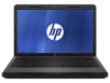
...finish 664237-001 Equipped with webcam, in charcoal gray finish 645093-001 Not equipped with webcam, in Hibernation, turn the computer on, and then shut it down the computer. Disconnect all external devices connected to the base enclosure. 3. Remove the two Phillips PM2.0×...;5.0 screws (2) that secure the optical drive connector to the computer. 62 Chapter 4 Removal and replacement procedures Remove...
...finish 664237-001 Equipped with webcam, in charcoal gray finish 645093-001 Not equipped with webcam, in Hibernation, turn the computer on, and then shut it down the computer. Disconnect all external devices connected to the base enclosure. 3. Remove the two Phillips PM2.0×...;5.0 screws (2) that secure the optical drive connector to the computer. 62 Chapter 4 Removal and replacement procedures Remove...
HP 2000 Notebook PC - Maintenance and Service Guide
Page 72
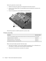
... replacement procedures Disconnect the module cable (2) from the display enclosure. If it is necessary to replace the webcam/microphone module or microphone module: a. Remove the two Mylar screw covers (1) and the two Phillips PM2.5×4.0 screws (2) that secure the display bezel to the display enclosure with double-sided tape.) b. ...
... replacement procedures Disconnect the module cable (2) from the display enclosure. If it is necessary to replace the webcam/microphone module or microphone module: a. Remove the two Mylar screw covers (1) and the two Phillips PM2.5×4.0 screws (2) that secure the display bezel to the display enclosure with double-sided tape.) b. ...
HP 2000 Notebook PC - Maintenance and Service Guide
Page 73
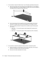
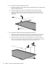
Remove the two Phillips PM2.5×5.0 (1) screws that secure the hinge covers to replace the hinge covers: a. The webcam/ microphone module is available using spare part number 646124-001. b. Remove the webcam/microphone module (3) or microphone module. The hinge covers are available using spare part number 646138-001. The microphone module is necessary to the display enclosure. Component replacement procedures 65 c. Remove the hinge covers (2). If it is available using spare part number 645980-001. 7.
Remove the two Phillips PM2.5×5.0 (1) screws that secure the hinge covers to replace the hinge covers: a. The webcam/ microphone module is available using spare part number 646124-001. b. Remove the webcam/microphone module (3) or microphone module. The hinge covers are available using spare part number 646138-001. The microphone module is necessary to the display enclosure. Component replacement procedures 65 c. Remove the hinge covers (2). If it is available using spare part number 645980-001. 7.
HP 2000 Notebook PC - Maintenance and Service Guide
Page 76
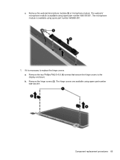
...clips (2) built into the display enclosure. The display panel cable includes the webcam/ microphone module cable and is available in the Antenna Kit, spare part number 646111-001. 68 Chapter 4 Removal and replacement procedures Release the wireless antenna transceiver (1) from the clips (2) ... it is necessary to replace the display panel cable: a. The wireless antenna cable and transceiver are attached to the display enclosure. Remove the display panel cable (3). Release the wireless antenna cable from the display enclosure. (The wireless antenna transceiver are available in the...
...clips (2) built into the display enclosure. The display panel cable includes the webcam/ microphone module cable and is available in the Antenna Kit, spare part number 646111-001. 68 Chapter 4 Removal and replacement procedures Release the wireless antenna transceiver (1) from the clips (2) ... it is necessary to replace the display panel cable: a. The wireless antenna cable and transceiver are attached to the display enclosure. Remove the display panel cable (3). Release the wireless antenna cable from the display enclosure. (The wireless antenna transceiver are available in the...
HP 2000 Notebook PC - Maintenance and Service Guide
Page 114
... audio-in 12 audio-out 12 headphone 12 microphone 12 network 12 RJ-45 12 K key components 9 keybaord spare part numbers 29 keyboard product description 5 removal 49 spare part numbers 18, 29, 49 keys Action 9 esc 9 fn 9 Windows applications 9 Windows logo 9 L left-side components 12 light components...13 caps lock 10 drive 12 optical drive 13 power 10, 12 TouchPad 10, 11 webcam 7 wireless 10 M mass storage device precautions 34 removal 46 spare part numbers 24, 46 memory module product description 3 removal 45 spare part numbers 21, 28, 45 memory module compartment 14 memory module/wireless ...
... audio-in 12 audio-out 12 headphone 12 microphone 12 network 12 RJ-45 12 K key components 9 keybaord spare part numbers 29 keyboard product description 5 removal 49 spare part numbers 18, 29, 49 keys Action 9 esc 9 fn 9 Windows applications 9 Windows logo 9 L left-side components 12 light components...13 caps lock 10 drive 12 optical drive 13 power 10, 12 TouchPad 10, 11 webcam 7 wireless 10 M mass storage device precautions 34 removal 46 spare part numbers 24, 46 memory module product description 3 removal 45 spare part numbers 21, 28, 45 memory module compartment 14 memory module/wireless ...
HP 2000 Notebook PC - Maintenance and Service Guide
Page 115
... 10, 11 TouchPad on/off button 11 TouchPad zone 11 transporting guidelines 36 W warranty period 39 webcam 7 webcam light 7 webcam/microphone module removal 64 spare part number 22, 30, 65 Windows applications key 9 Windows logo key 9 wireless antenna locations 7 removal 68 spare part number 22, 28, 68 wireless light 10 wireless, product description 4 WLAN module...
... 10, 11 TouchPad on/off button 11 TouchPad zone 11 transporting guidelines 36 W warranty period 39 webcam 7 webcam light 7 webcam/microphone module removal 64 spare part number 22, 30, 65 Windows applications key 9 Windows logo key 9 wireless antenna locations 7 removal 68 spare part number 22, 28, 68 wireless light 10 wireless, product description 4 WLAN module...
Getting Started HP Notebook - Windows 7
Page 54
...esc key, identifying 7 external monitor port 9 F f11 37 flicking TouchPad gesture 24 fn key, identifying 7 H hard drive installing 28 removing 27 hard drive bay, identifying 11 HDMI port, identifying 9 headphone (audio-out) jack, identifying 9 Help and Support action key 18... HP Recovery Manager 37 C caps lock light, identifying 5 Certificate of Authenticity label 43 components bottom 11 I input power 44 integrated webcam light, identifying 10 internal microphone, identifying 10 Internet connection setup 16 ISP, using ...
...esc key, identifying 7 external monitor port 9 F f11 37 flicking TouchPad gesture 24 fn key, identifying 7 H hard drive installing 28 removing 27 hard drive bay, identifying 11 HDMI port, identifying 9 headphone (audio-out) jack, identifying 9 Help and Support action key 18... HP Recovery Manager 37 C caps lock light, identifying 5 Certificate of Authenticity label 43 components bottom 11 I input power 44 integrated webcam light, identifying 10 internal microphone, identifying 10 Internet connection setup 16 ISP, using ...
Getting Started HP Notebook - Windows 7
Page 55
... 30 memory module compartment cover removing 27, 31 replacing 29, 33 memory module compartment, identifying 11 Microsoft Certificate of Authenticity label 43 mouse, external setting preferences 20 mute key...zone, identifying 4 traveling with the computer 43 U USB ports, identifying 8, 9 using system restore 41 V vents, identifying 9, 11 volume keys, identifying 19 W webcam light, identifying 10 webcam, identifying 10 Windows applications key, identifying 7 Windows logo key, identifying 7 wireless certification label 43 wireless key, identifying 19 wireless light 5 wireless network (WLAN), ...
... 30 memory module compartment cover removing 27, 31 replacing 29, 33 memory module compartment, identifying 11 Microsoft Certificate of Authenticity label 43 mouse, external setting preferences 20 mute key...zone, identifying 4 traveling with the computer 43 U USB ports, identifying 8, 9 using system restore 41 V vents, identifying 9, 11 volume keys, identifying 19 W webcam light, identifying 10 webcam, identifying 10 Windows applications key, identifying 7 Windows logo key, identifying 7 wireless certification label 43 wireless key, identifying 19 wireless light 5 wireless network (WLAN), ...


