Maintenance and Service Guide
Page 6
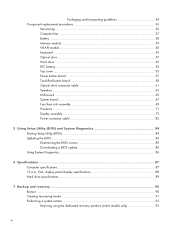
...37 Battery ...38 Memory module ...39 WLAN module ...40 Keyboard ...43 Optical drive ...47 Hard drive ...49 RTC battery ...52 Top cover ...53 Power button board 57 TouchPad button board 58 Optical drive connector cable 61 Speakers ...63 USB board ...65 System board ...67 Fan/heat sink assembly 69 Processor ...71 Display assembly ...73 Power connector cable 82 5 Using Setup Utility (BIOS) and System Diagnostics 84 Starting Setup Utility (BIOS) ...84 Updating the BIOS ...84 Determining the BIOS version 85 Downloading a BIOS update 85 Using System Diagnostics ...86 6 Specifications ...87...
...37 Battery ...38 Memory module ...39 WLAN module ...40 Keyboard ...43 Optical drive ...47 Hard drive ...49 RTC battery ...52 Top cover ...53 Power button board 57 TouchPad button board 58 Optical drive connector cable 61 Speakers ...63 USB board ...65 System board ...67 Fan/heat sink assembly 69 Processor ...71 Display assembly ...73 Power connector cable 82 5 Using Setup Utility (BIOS) and System Diagnostics 84 Starting Setup Utility (BIOS) ...84 Updating the BIOS ...84 Determining the BIOS version 85 Downloading a BIOS update 85 Using System Diagnostics ...86 6 Specifications ...87...
Maintenance and Service Guide
Page 12
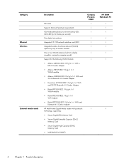
Category Ethernet Wireless External media cards Description HD audio Supports Microsoft premium requirements VGA webcamera (fixed, no tilt with activity LED; 640×480 by 24 frames per second) One digital microphone Integrated 10/100 network interface card (NIC) Integrated wireless local area network (WLAN) options by way of wireless module One or two WLAN antennas built into display assembly, varying by computer model Support for the following WLAN formats: ● Atheros...
Category Ethernet Wireless External media cards Description HD audio Supports Microsoft premium requirements VGA webcamera (fixed, no tilt with activity LED; 640×480 by 24 frames per second) One digital microphone Integrated 10/100 network interface card (NIC) Integrated wireless local area network (WLAN) options by way of wireless module One or two WLAN antennas built into display assembly, varying by computer model Support for the following WLAN formats: ● Atheros...
Maintenance and Service Guide
Page 13
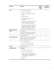
... enabled, twofinger scrolling, and pinch-zoom as default Taps enabled by default 65W RC, V, EM, 3-wire HP Smart AC adapter with localized cable plug support (3-wire plug with 2-GB of system memory) ● FreeDOS Compaq Presario CQ58 √ √ √ HP 2000 Notebook PC √ 5 USB port allocation: 3 for the computer, 1 for camera 1 for MiniCard) ● VGA (Dsub 15 pin) supporting: 2048×1536 external resolution @ 75 Hz, hot...
... enabled, twofinger scrolling, and pinch-zoom as default Taps enabled by default 65W RC, V, EM, 3-wire HP Smart AC adapter with localized cable plug support (3-wire plug with 2-GB of system memory) ● FreeDOS Compaq Presario CQ58 √ √ √ HP 2000 Notebook PC √ 5 USB port allocation: 3 for the computer, 1 for camera 1 for MiniCard) ● VGA (Dsub 15 pin) supporting: 2048×1536 external resolution @ 75 Hz, hot...
Maintenance and Service Guide
Page 21
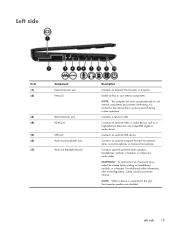
...: When a device is normal for the internal fan to cool internal components. Left side Item (1) (2) (3) (4) (5) (6) (7) Component External monitor port Vents (2) RJ-45 (network) jack HDMI port USB port Audio-in (microphone) jack Audio-out (headphone) jack Description Connects an external VGA monitor or projector. Connects optional powered stereo speakers, headphones, earbuds, a headset, or a television audio cable. Enable airflow to cycle on headphones, earbuds, or a headset. Connects an optional USB device. To reduce the risk of personal injury, adjust the volume before putting...
...: When a device is normal for the internal fan to cool internal components. Left side Item (1) (2) (3) (4) (5) (6) (7) Component External monitor port Vents (2) RJ-45 (network) jack HDMI port USB port Audio-in (microphone) jack Audio-out (headphone) jack Description Connects an external VGA monitor or projector. Connects optional powered stereo speakers, headphones, earbuds, a headset, or a television audio cable. Enable airflow to cycle on headphones, earbuds, or a headset. Connects an optional USB device. To reduce the risk of personal injury, adjust the volume before putting...
Maintenance and Service Guide
Page 26
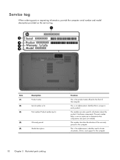
... components and parts are needed. This number provides specific information about the product's hardware components. The part number helps a service technician to each product. This number describes the duration of the computer. This is the product name affixed to locate documents, drivers, and support for the computer. Item (1) (2) (3) Description Product name Serial number (s/n) Part number/Product number (p/n) (4) Warranty period (5) Model description Function This is the alphanumeric identifier used to the...
... components and parts are needed. This number provides specific information about the product's hardware components. The part number helps a service technician to each product. This number describes the duration of the computer. This is the product name affixed to locate documents, drivers, and support for the computer. Item (1) (2) (3) Description Product name Serial number (s/n) Part number/Product number (p/n) (4) Warranty period (5) Model description Function This is the alphanumeric identifier used to the...
Maintenance and Service Guide
Page 29
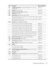
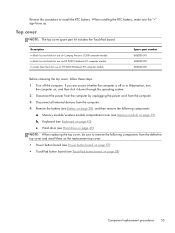
...) (12) (13) (14) (15) (16) (17) Component Spare part number TouchPad button board (includes bracket, TouchPad button board cable, and TouchPad cable) 686271-001 Speakers (include speaker cables) 686279-001 Optical drive connector cable (includes bracket) 686257-001 USB board (includes cable) 686269-001 System board (includes replacement thermal material): Equipped with Intel HM75 Express chipset and for use with computer models equipped 686280-001 with an Intel Core i5 or...
...) (12) (13) (14) (15) (16) (17) Component Spare part number TouchPad button board (includes bracket, TouchPad button board cable, and TouchPad cable) 686271-001 Speakers (include speaker cables) 686279-001 Optical drive connector cable (includes bracket) 686257-001 USB board (includes cable) 686269-001 System board (includes replacement thermal material): Equipped with Intel HM75 Express chipset and for use with computer models equipped 686280-001 with an Intel Core i5 or...
Maintenance and Service Guide
Page 33
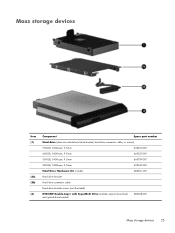
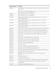
Mass storage devices Item (1) (2a) (2b) (3) Component Spare part number Hard drive (does not include hard drive bracket, hard drive connector cable, or screws): 750-GB, 5400-rpm, 9.5-mm 634250-001 640-GB, 5400-rpm, 9.5-mm 669300-001 500-GB, 5400-rpm, 9.5-mm 669299-001 320-GB, 5400-rpm, 9.5-mm 622643-001 Hard Drive Hardware Kit, includes: 686261-001 Hard drive bracket Hard drive connector cable Hard drive bracket screws (not illustrated) DVD±RW Double-Layer with SuperMulti Drive (includes optical drive bezel and optical drive bracket) 686268-001 Mass storage devices 25
Mass storage devices Item (1) (2a) (2b) (3) Component Spare part number Hard drive (does not include hard drive bracket, hard drive connector cable, or screws): 750-GB, 5400-rpm, 9.5-mm 634250-001 640-GB, 5400-rpm, 9.5-mm 669300-001 500-GB, 5400-rpm, 9.5-mm 669299-001 320-GB, 5400-rpm, 9.5-mm 622643-001 Hard Drive Hardware Kit, includes: 686261-001 Hard drive bracket Hard drive connector cable Hard drive bracket screws (not illustrated) DVD±RW Double-Layer with SuperMulti Drive (includes optical drive bezel and optical drive bracket) 686268-001 Mass storage devices 25
Maintenance and Service Guide
Page 37
..., hard drive connector cable, and screws) 686262-001 Display hinges (includes vertical support brackets) 686268-001 DVD±RW Double-Layer with SuperMulti Drive (includes optical drive bezel and optical drive bracket) 686269-001 USB board (includes cable) 686270-001 Power button board (includes cable) 686271-001 TouchPad button board (includes bracket, TouchPad button board cable, and TouchPad cable) 686272-001 Cover Kit (includes hard drive compartment cover and memory module/wireless module compartment cover) 686273-001 15.6-in the Hard Drive Hardware Kit, spare part number...
..., hard drive connector cable, and screws) 686262-001 Display hinges (includes vertical support brackets) 686268-001 DVD±RW Double-Layer with SuperMulti Drive (includes optical drive bezel and optical drive bracket) 686269-001 USB board (includes cable) 686270-001 Power button board (includes cable) 686271-001 TouchPad button board (includes bracket, TouchPad button board cable, and TouchPad cable) 686272-001 Cover Kit (includes hard drive compartment cover and memory module/wireless module compartment cover) 686273-001 15.6-in the Hard Drive Hardware Kit, spare part number...
Maintenance and Service Guide
Page 55
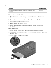
... Memory module on , and then shut it down through the operating system. 2. Use a flat-blade screw driver or similar tool to press on page 38). 5. Remove the optical drive (3) from the computer. 4. Optical drive Description DVD±RW Double-Layer with SuperMulti Drive (includes optical drive bezel and optical drive bracket) Spare part number 686268-001 Before removing the optical drive, follow these steps: 1. Disconnect all external devices...
... Memory module on , and then shut it down through the operating system. 2. Use a flat-blade screw driver or similar tool to press on page 38). 5. Remove the optical drive (3) from the computer. 4. Optical drive Description DVD±RW Double-Layer with SuperMulti Drive (includes optical drive bezel and optical drive bracket) Spare part number 686268-001 Before removing the optical drive, follow these steps: 1. Disconnect all external devices...
Maintenance and Service Guide
Page 57
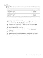
... the computer. Remove the memory module/wireless module compartment cover (see Battery on page 39). Disconnect the power from the computer by unplugging the power cord from the computer. 4. Description 750-GB, 5400-rpm, 9.5-mm 640-GB, 5400-rpm, 9.5-mm 500-GB, 5400-rpm, 9.5-mm 320-GB, 5400-rpm, 9.5-mm Hard Drive Hardware Kit (includes hard drive bracket, hard drive connector cable, and screws) Spare part number 634250-001...
... the computer. Remove the memory module/wireless module compartment cover (see Battery on page 39). Disconnect the power from the computer by unplugging the power cord from the computer. 4. Description 750-GB, 5400-rpm, 9.5-mm 640-GB, 5400-rpm, 9.5-mm 500-GB, 5400-rpm, 9.5-mm 320-GB, 5400-rpm, 9.5-mm Hard Drive Hardware Kit (includes hard drive bracket, hard drive connector cable, and screws) Spare part number 634250-001...
Maintenance and Service Guide
Page 60
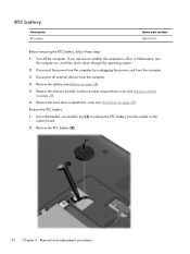
... all external devices from the computer. 3. Remove the memory module/wireless module compartment cover (see Battery on page 38). 5. Remove the RTC battery (2). 52 Chapter 4 Removal and replacement procedures Remove the RTC battery: 1. Remove the battery (see Memory module on , and then shut it down through the operating system. 2. Remove the hard drive compartment cover (see Hard drive on the system board. 2. Use a flat-bladed, non-metallic tool (1) to release the RTC battery from the socket on page 49). Turn...
... all external devices from the computer. 3. Remove the memory module/wireless module compartment cover (see Battery on page 38). 5. Remove the RTC battery (2). 52 Chapter 4 Removal and replacement procedures Remove the RTC battery: 1. Remove the battery (see Memory module on , and then shut it down through the operating system. 2. Remove the hard drive compartment cover (see Hard drive on the system board. 2. Use a flat-bladed, non-metallic tool (1) to release the RTC battery from the socket on page 49). Turn...
Maintenance and Service Guide
Page 61
... to remove the following components: a. Memory module/wireless module compartment cover (see Keyboard on page 39) b. Keyboard (see Memory module on page 43) c. Remove the battery (see Hard drive on , and then shut it down through the operating system. 2. When installing the RTC battery, make sure the "+" sign faces up. Disconnect the power from the computer by unplugging the power cord from the computer. 4. Disconnect all external devices from the computer. 3. Turn off...
... to remove the following components: a. Memory module/wireless module compartment cover (see Keyboard on page 39) b. Keyboard (see Memory module on page 43) c. Remove the battery (see Hard drive on , and then shut it down through the operating system. 2. When installing the RTC battery, make sure the "+" sign faces up. Disconnect the power from the computer by unplugging the power cord from the computer. 4. Disconnect all external devices from the computer. 3. Turn off...
Maintenance and Service Guide
Page 92
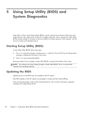
... operating properly. Most BIOS updates on the HP website. NOTE: Use extreme care when making changes in Setup Utility (BIOS) is displayed at the bottom of the screen. Updating the BIOS Updated versions of the BIOS may be available on the HP website are packaged in compressed files called SoftPaqs. Setup Utility (BIOS) includes settings for Startup Menu" message is located at the bottom of the screen. 2. Turn on the system (such as disk drives, display, keyboard, mouse, and printer). Some download...
... operating properly. Most BIOS updates on the HP website. NOTE: Use extreme care when making changes in Setup Utility (BIOS) is displayed at the bottom of the screen. Updating the BIOS Updated versions of the BIOS may be available on the HP website are packaged in compressed files called SoftPaqs. Setup Utility (BIOS) includes settings for Startup Menu" message is located at the bottom of the screen. 2. Turn on the system (such as disk drives, display, keyboard, mouse, and printer). Some download...
Maintenance and Service Guide
Page 93
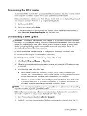
... downloaded. Do not insert, remove, connect, or disconnect any software updates, especially system BIOS updates. Follow the on your selection to an optional power source. Select Start > Help and Support > Maintain. 2. Make a note of damage to the computer or an unsuccessful installation, download and install a BIOS update only when the computer is running on the computer, you are already in an optional docking device, or connected to the hard drive. BIOS installation procedures vary. Open Windows...
... downloaded. Do not insert, remove, connect, or disconnect any software updates, especially system BIOS updates. Follow the on your selection to an optional power source. Select Start > Help and Support > Maintain. 2. Make a note of damage to the computer or an unsuccessful installation, download and install a BIOS update only when the computer is running on the computer, you are already in an optional docking device, or connected to the hard drive. BIOS installation procedures vary. Open Windows...
Maintenance and Service Guide
Page 98
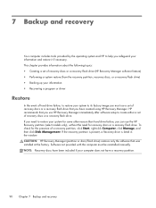
...have a recovery partition. 90 Chapter 7 Backup and recovery HP recommends that you can use a set of recovery discs or a recovery flash drive (HP Recovery Manager software feature) ● Performing a system restore (from the recovery partition, recovery discs, or a recovery flash drive) ● Backing up your information ● Recovering a program or driver Restore In the event of recovery discs or a recovery flash drive that was installed at the factory. This chapter provides information about the following topics: ● Creating a set of hard drive failure, to restore your...
...have a recovery partition. 90 Chapter 7 Backup and recovery HP recommends that you can use a set of recovery discs or a recovery flash drive (HP Recovery Manager software feature) ● Performing a system restore (from the recovery partition, recovery discs, or a recovery flash drive) ● Backing up your information ● Recovering a program or driver Restore In the event of recovery discs or a recovery flash drive that was installed at the factory. This chapter provides information about the following topics: ● Creating a set of hard drive failure, to restore your...
Maintenance and Service Guide
Page 99
... one set of recovery discs or one recovery flash drive can be connected directly to a USB port on the computer, not to create recovery discs, or you can restore your computer from the HP website. The next time you open HP Recovery Manager, you use an optional external optical drive (purchased separately) to a USB port on -screen instructions. Creating recovering media 91 Handle these discs or the flash drive after setting up the computer for your computer to continue the backup creation process. Creating recovering media HP recommends...
... one set of recovery discs or one recovery flash drive can be connected directly to a USB port on the computer, not to create recovery discs, or you can restore your computer from the HP website. The next time you open HP Recovery Manager, you use an optional external optical drive (purchased separately) to a USB port on -screen instructions. Creating recovering media 91 Handle these discs or the flash drive after setting up the computer for your computer to continue the backup creation process. Creating recovering media HP recommends...
Maintenance and Service Guide
Page 100
.... Access HP Recovery Manager in the HP Recovery Manager window. 3. Click System Recovery in either of recovery discs or a recovery flash drive. ● Windows has its original factory state. Follow the on the hard drive. To restore the computer from the disc provided by the manufacturer. HP Recovery Manager works from recovery discs or a recovery flash drive, or from a dedicated recovery partition (select models only) on -screen instructions. 92 Chapter 7 Backup and recovery Note the following ways: ● Select Start > All Programs > HP Help and Support > HP Recovery Manager...
.... Access HP Recovery Manager in the HP Recovery Manager window. 3. Click System Recovery in either of recovery discs or a recovery flash drive. ● Windows has its original factory state. Follow the on the hard drive. To restore the computer from the disc provided by the manufacturer. HP Recovery Manager works from recovery discs or a recovery flash drive, or from a dedicated recovery partition (select models only) on -screen instructions. 92 Chapter 7 Backup and recovery Note the following ways: ● Select Start > All Programs > HP Help and Support > HP Recovery Manager...
Maintenance and Service Guide
Page 108
... button 9 display 7 front 12 keys 10 left-side 13 lights 11 right-side 15 TouchPad 12 computer feet locations 37 spare part number 21, 30 computer major components 19 computer part number 36 computer specifications 87 connectors, service considerations 31 Cover Kit, spare part number 22, 29, 39, 50 D Digital Media slot 14 display components 7 specifications 88 display assembly removal 73 spare part number 73 subcomponents 23 display bezel removal 75 spare part numbers 23, 29, 75 display...
... button 9 display 7 front 12 keys 10 left-side 13 lights 11 right-side 15 TouchPad 12 computer feet locations 37 spare part number 21, 30 computer major components 19 computer part number 36 computer specifications 87 connectors, service considerations 31 Cover Kit, spare part number 22, 29, 39, 50 D Digital Media slot 14 display components 7 specifications 88 display assembly removal 73 spare part number 73 subcomponents 23 display bezel removal 75 spare part numbers 23, 29, 75 display...

Maintenance and Service Guide
Page 109
... device, product description 5 ports external monitor port 13 HDMI 13 monitor port 13 product description 5 USB 13, 15 power button 9 power button board removal 57 spare part number 20, 29, 57 power connector 15 power connector cable removal 82 spare part number 21, 29, 82 power cord set requirements 97 spare part numbers 26, 27 power light 11, 14 power requirements, product description 5 processor product description 1 removal 71 spare part numbers 21, 28, 29, 30, 71 product description audio 3 chipset 2 display panel 2 Ethernet 4 external media cards 4 graphics 2 hard drive 3 keyboard...
... device, product description 5 ports external monitor port 13 HDMI 13 monitor port 13 product description 5 USB 13, 15 power button 9 power button board removal 57 spare part number 20, 29, 57 power connector 15 power connector cable removal 82 spare part number 21, 29, 82 power cord set requirements 97 spare part numbers 26, 27 power light 11, 14 power requirements, product description 5 processor product description 1 removal 71 spare part numbers 21, 28, 29, 30, 71 product description audio 3 chipset 2 display panel 2 Ethernet 4 external media cards 4 graphics 2 hard drive 3 keyboard...
Maintenance and Service Guide
Page 110
... part number 26, 30 security cable slot 15 security, product description 5 serial number 36 service considerations cables 31 connectors 31 plastic parts 31 service tag 18, 36 serviceability, product description 6 speakers location 12 removal 63 spare part number 21, 30, 63 specifications computer 87 display 88 hard drive 89 V vents 13, 16 video, product description 3 W warranty period 37 webcam 8 webcam light 8 webcam/microphone module removal 81 spare part number 23, 30, 81 Windows applications key 10 Windows logo key 10 wireless antenna locations 7 removal 81 spare part number...
... part number 26, 30 security cable slot 15 security, product description 5 serial number 36 service considerations cables 31 connectors 31 plastic parts 31 service tag 18, 36 serviceability, product description 6 speakers location 12 removal 63 spare part number 21, 30, 63 specifications computer 87 display 88 hard drive 89 V vents 13, 16 video, product description 3 W warranty period 37 webcam 8 webcam light 8 webcam/microphone module removal 81 spare part number 23, 30, 81 Windows applications key 10 Windows logo key 10 wireless antenna locations 7 removal 81 spare part number...


