Illustrated Parts & Service Map HP 100B All-in-One
Page 1
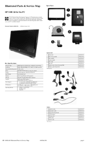
... 646783-001 646784-001 646785-001 646794-001 646795-001 Cables 1 Hard drive cable 2 Optical drive cable 3 Power button board cable 4 WLAN antenna * Webcam cable * LVDS cable * Inverter cable *Not shown 646789-001 646790-001 646782-001 646806-001 646786-001 646787-001 646788-001 HP 100B AIO Illustrated Parts & Service Map 640046-001 page 1 Key ...750 GB, 500 GB, 250 GB) (6) USB ports - 2 side, 4 rear, (1) Headphone jack, (1) Line-out, (1) Microphone-in the U. Illustrated Parts & Service Map Spare Parts HP 100B All-In One PC © 2011 Hewlett-Packard Development Company, L.P.
... 646783-001 646784-001 646785-001 646794-001 646795-001 Cables 1 Hard drive cable 2 Optical drive cable 3 Power button board cable 4 WLAN antenna * Webcam cable * LVDS cable * Inverter cable *Not shown 646789-001 646790-001 646782-001 646806-001 646786-001 646787-001 646788-001 HP 100B AIO Illustrated Parts & Service Map 640046-001 page 1 Key ...750 GB, 500 GB, 250 GB) (6) USB ports - 2 side, 4 rear, (1) Headphone jack, (1) Line-out, (1) Microphone-in the U. Illustrated Parts & Service Map Spare Parts HP 100B All-In One PC © 2011 Hewlett-Packard Development Company, L.P.
Illustrated Parts & Service Map HP 100B All-in-One
Page 3
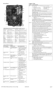
...the last boot (memory added or removed). Press the F1 key to set and enable power-on next boot • SOL Terminal Emulation Mode • SOL Local Keyboard (enable/disable) HP 100B AIO Illustrated Parts & Service Map 640046-001 page 3 Remove and replace identified faulty memory module...Jumpers (component location may be through the embedded solution or one of the installed NIC cards. Clear CMOS. If third-party memory added, test using HP-only memory. 1. Ensure memory modules are correctly installed. 2. Reseat fan cable. 3. Upgrade BIOS to turn on a network server. Change...
...the last boot (memory added or removed). Press the F1 key to set and enable power-on next boot • SOL Terminal Emulation Mode • SOL Local Keyboard (enable/disable) HP 100B AIO Illustrated Parts & Service Map 640046-001 page 3 Remove and replace identified faulty memory module...Jumpers (component location may be through the embedded solution or one of the installed NIC cards. Clear CMOS. If third-party memory added, test using HP-only memory. 1. Ensure memory modules are correctly installed. 2. Reseat fan cable. 3. Upgrade BIOS to turn on a network server. Change...
Maintenance & Service Guide HP 100B All-in-One
Page 6
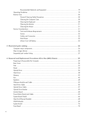
... parts catalog 24 Computer major components 24 Mass storage devices ...26 Sequential part number listing 27 6 Removal and Replacement Procedures All-in One (AIO) Chassis 29 Preparing to Disassemble the Computer 29 Rear Cover ...30 Feet ...33 Stand ...34 Optical Drive ...36 Hard Drive ...38... Memory ...42 Fan ...45 Speakers ...48 Webcam Module and Cable 52 Hard Drive Cable ...55 Optical Drive Cable ...57 Optical Drive Bracket ...59 Inverter Board ...60 Power Button Board and Cable 63 System Board Shield ...66 Heat Sink (Thermal Module) ...68 WLAN Module ...69...
... parts catalog 24 Computer major components 24 Mass storage devices ...26 Sequential part number listing 27 6 Removal and Replacement Procedures All-in One (AIO) Chassis 29 Preparing to Disassemble the Computer 29 Rear Cover ...30 Feet ...33 Stand ...34 Optical Drive ...36 Hard Drive ...38... Memory ...42 Fan ...45 Speakers ...48 Webcam Module and Cable 52 Hard Drive Cable ...55 Optical Drive Cable ...57 Optical Drive Bracket ...59 Inverter Board ...60 Power Button Board and Cable 63 System Board Shield ...66 Heat Sink (Thermal Module) ...68 WLAN Module ...69...
Maintenance & Service Guide HP 100B All-in-One
Page 37
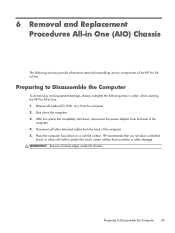
... or other soft cloth to Disassemble the Computer 29 HP recommends that you set down , disconnect the power adapter from the back of the computer. 4. 6 Removal and Replacement Procedures All-in One (AIO) Chassis The following steps in order, when opening the HP Pro All-in-One. 1. Place the computer face down the computer. ... sections provide information about disassembling various components of sharp edges inside the chassis. Shut down on a soft flat surface. Beware of the HP Pro Allin-One. WARNING! Remove all other attached cables from the back of the computer. 5.
... or other soft cloth to Disassemble the Computer 29 HP recommends that you set down , disconnect the power adapter from the back of the computer. 4. 6 Removal and Replacement Procedures All-in One (AIO) Chassis The following steps in order, when opening the HP Pro All-in-One. 1. Place the computer face down the computer. ... sections provide information about disassembling various components of sharp edges inside the chassis. Shut down on a soft flat surface. Beware of the HP Pro Allin-One. WARNING! Remove all other attached cables from the back of the computer. 5.

Maintenance & Service Guide HP 100B All-in-One
Page 72
... board 5. Remove the board from the power button board (1) and the system board (2). 64 Chapter 6 Removal and Replacement Procedures All-in One (AIO) Chassis Remove the rear cover (see Preparing to damage the cables when disconnecting them from the board (3). Disconnect the cable from the computer. Prepare the computer for disassembly (see Rear Cover on...
... board 5. Remove the board from the power button board (1) and the system board (2). 64 Chapter 6 Removal and Replacement Procedures All-in One (AIO) Chassis Remove the rear cover (see Preparing to damage the cables when disconnecting them from the board (3). Disconnect the cable from the computer. Prepare the computer for disassembly (see Rear Cover on...
Maintenance & Service Guide HP 100B All-in-One
Page 74
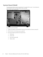
... route to the system board to Disassemble the Computer on page 30). 3. Disconnect the following cables from the system board: ● WLAN cable ● Inverter cable ● Power button board cable ● Webcam cable 66 Chapter 6 Removal and Replacement Procedures All-in One (AIO) Chassis It is secured with five screws. Prepare the computer for disassembly (see Rear...
... route to the system board to Disassemble the Computer on page 30). 3. Disconnect the following cables from the system board: ● WLAN cable ● Inverter cable ● Power button board cable ● Webcam cable 66 Chapter 6 Removal and Replacement Procedures All-in One (AIO) Chassis It is secured with five screws. Prepare the computer for disassembly (see Rear...


