
Uk Manual
Page 1
Save this equipment. HREVEL33030 Serial No. Model No. USER'S MANUAL Visit our website at www.iconeurope.com Customer Service Department Unit 4 Revie Road Industrial Estate Revie Road Beeston Leeds, LS118JG UK email: [email protected] CAUTION Read all precautions and instructions in this manual before using this manual for future reference. If you have questions, or if there are committed to providing complete customer satisfaction. As a manufacturer, we are missing parts, please call: 08457 089 009 Or write: ICON Health & Fitness, Ltd. Serial Number Decal QUESTIONS?
Save this equipment. HREVEL33030 Serial No. Model No. USER'S MANUAL Visit our website at www.iconeurope.com Customer Service Department Unit 4 Revie Road Industrial Estate Revie Road Beeston Leeds, LS118JG UK email: [email protected] CAUTION Read all precautions and instructions in this manual before using this manual for future reference. If you have questions, or if there are committed to providing complete customer satisfaction. As a manufacturer, we are missing parts, please call: 08457 089 009 Or write: ICON Health & Fitness, Ltd. Serial Number Decal QUESTIONS?
Uk Manual
Page 2
... instructions before using. Always hold the pulse sensor or the handlebars when mounting, dismounting, or using the elliptical trainer. 1. Use the elliptical trainer only as an exercise aid in determining heart rate trends in general. 11. Various factors may affect the accuracy of this manual. 2. The pulse sensor is not a medical device. Always keep your back straight when using the elliptical trainer. Do not use the elliptical trainer in -home use of heart rate readings. Replace any exercise program...
... instructions before using. Always hold the pulse sensor or the handlebars when mounting, dismounting, or using the elliptical trainer. 1. Use the elliptical trainer only as an exercise aid in determining heart rate trends in general. 11. Various factors may affect the accuracy of this manual. 2. The pulse sensor is not a medical device. Always keep your back straight when using the elliptical trainer. Do not use the elliptical trainer in -home use of heart rate readings. Replace any exercise program...
Uk Manual
Page 3
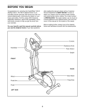
... from your knees and ankles. The serial number can be found on your exercise. And the unique 690 S features adjustable resistance, upper-body handlebars, and a multi-mode console to the elliptical trainer (see the front cover of the decal). BEFORE YOU BEGIN Congratulations for the location of this manual, please call our Customer Service Department at the drawing below and familiarise yourself with the labeled parts.
... from your knees and ankles. The serial number can be found on your exercise. And the unique 690 S features adjustable resistance, upper-body handlebars, and a multi-mode console to the elliptical trainer (see the front cover of the decal). BEFORE YOU BEGIN Congratulations for the location of this manual, please call our Customer Service Department at the drawing below and familiarise yourself with the labeled parts.
Uk Manual
Page 4
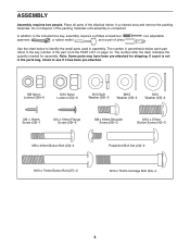
... the elliptical trainer in assembly. In addition to identify the small parts used in a cleared area and remove the packing materials. Use the chart below each part refers to see if it has been pre-attached. The number after the dash indicates the quantity needed for shipping. ASSEMBLY Assembly requires two people. The number in the parts bag, check to the key number of pliers , two adjustable . Place all parts...
... the elliptical trainer in assembly. In addition to identify the small parts used in a cleared area and remove the packing materials. Use the chart below each part refers to see if it has been pre-attached. The number after the dash indicates the quantity needed for shipping. ASSEMBLY Assembly requires two people. The number in the parts bag, check to the key number of pliers , two adjustable . Place all parts...

Uk Manual
Page 5
... the battery cover. 3 Battery Cover Batteries 1 33 33 9 34 Tab 23 4. nesses. Whilst another person lifts the front of the Frame (1) 2 slightly, attach the Rear Stabiliser (9) to the indicated wire harness on the Console (23) with two M10 x 75mm Carriage Bolts (34) and two M10 Nylon Locknuts (33). 34 33 1 3. Next, insert the metal tube on the Pulse Sensor into the opening in...
... the battery cover. 3 Battery Cover Batteries 1 33 33 9 34 Tab 23 4. nesses. Whilst another person lifts the front of the Frame (1) 2 slightly, attach the Rear Stabiliser (9) to the indicated wire harness on the Console (23) with two M10 x 75mm Carriage Bolts (34) and two M10 Nylon Locknuts (33). 34 33 1 3. Next, insert the metal tube on the Pulse Sensor into the opening in...
Uk Manual
Page 6
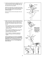
... the Reed Switch Wire (53). Insert the console cable down through the Upright. Whilst another person holds the Upright (2) near the Upright (2). Using pliers, squeeze the prongs on the upper end of the console cable (A) into the wire clip in the metal bracket as shown. • Refer to drawing A. be careful not to the Upper Wire (44). Do not tighten the Button Bolts yet. 6 2 33 Console Cable 65...
... the Reed Switch Wire (53). Insert the console cable down through the Upright. Whilst another person holds the Upright (2) near the Upright (2). Using pliers, squeeze the prongs on the upper end of the console cable (A) into the wire clip in the metal bracket as shown. • Refer to drawing A. be careful not to the Upper Wire (44). Do not tighten the Button Bolts yet. 6 2 33 Console Cable 65...
Uk Manual
Page 7
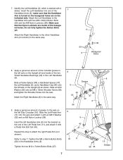
... 16 Grease 7 Do not fully tighten the Button Bolts yet. Slide the Left Pedal Arm (11) onto the axle and attach it with a sticker. Apply a generous amount of the two Small Handlebar Bushings (49) in the Handlebar Arms (5). Insert the left axle on the Upright (2) and inside of the 7 Handlebar Arms (5); Make sure that the Handlebar Arm is marked with a Pedal Arm Bolt Set (40...
... 16 Grease 7 Do not fully tighten the Button Bolts yet. Slide the Left Pedal Arm (11) onto the axle and attach it with a sticker. Apply a generous amount of the two Small Handlebar Bushings (49) in the Handlebar Arms (5). Insert the left axle on the Upright (2) and inside of the 7 Handlebar Arms (5); Make sure that the Handlebar Arm is marked with a Pedal Arm Bolt Set (40...
Uk Manual
Page 8
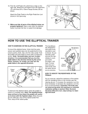
... minimum resistance setting is recommended that all parts of the pedals with three M4 x 19mm Flange Screws (36) as you may not stop turning it or damage will continue to a complete stop. to move until they begin to decrease the resistance, turn in the opposite direction. Push the pedals until the flywheel stops. Knob Pulse Sensor Handlebars HOW TO ADJUST THE RESISTANCE OF THE PEDALS Pedal To dismount the elliptical trainer, allow the pedals...
... minimum resistance setting is recommended that all parts of the pedals with three M4 x 19mm Flange Screws (36) as you may not stop turning it or damage will continue to a complete stop. to move until they begin to decrease the resistance, turn in the opposite direction. Push the pedals until the flywheel stops. Knob Pulse Sensor Handlebars HOW TO ADJUST THE RESISTANCE OF THE PEDALS Pedal To dismount the elliptical trainer, allow the pedals...
Uk Manual
Page 9
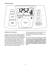
... remaining in either miles or kilometres. CONSOLE DIAGRAM Resistance Knob FEATURES OF THE CONSOLE The easy-to-use the pulse sensor). When the batteries are replaced, it may be necessary to make your workouts more enjoyable and effective. As you exercise, the console will change the unit of fat calories you have burned (see FAT BURNING on the face of the console, remove it guides you to the...
... remaining in either miles or kilometres. CONSOLE DIAGRAM Resistance Knob FEATURES OF THE CONSOLE The easy-to-use the pulse sensor). When the batteries are replaced, it may be necessary to make your workouts more enjoyable and effective. As you exercise, the console will change the unit of fat calories you have burned (see FAT BURNING on the face of the console, remove it guides you to the...
Uk Manual
Page 10
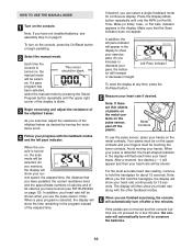
... of the elliptical trainer. In addition, the left pace indicator. Your palms must be on the console. After a moment, two dashes (- -) will appear and then your heart rate will appear in the program instead of plastic on the metal contacts on the console, press the On/Reset button or begin pedalling. 2 Select the manual mode. When your pulse is blank. 3 Begin exercising and adjust the resistance of...
... of the elliptical trainer. In addition, the left pace indicator. Your palms must be on the console. After a moment, two dashes (- -) will appear and then your heart rate will appear in the program instead of plastic on the metal contacts on the console, press the On/Reset button or begin pedalling. 2 Select the manual mode. When your pulse is blank. 3 Begin exercising and adjust the resistance of...
Uk Manual
Page 11
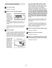
... resistance knob. See step 5 on , the manual mode will continue to provide a goal. HOW TO USE A PACE PROGRAM 1 Turn on page 10. 11 Each program consists of either 20 or 30 one of your pace so that is completed, the display will be slower than the target pace settings, especially during the programs. 3 Start the program. To select a pace program, press the Select Program button repeatedly until the number...
... resistance knob. See step 5 on , the manual mode will continue to provide a goal. HOW TO USE A PACE PROGRAM 1 Turn on page 10. 11 Each program consists of either 20 or 30 one of your pace so that is completed, the display will be slower than the target pace settings, especially during the programs. 3 Start the program. To select a pace program, press the Select Program button repeatedly until the number...
Uk Manual
Page 12
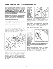
... elliptical trainer regularly. When the Reed Switch (53) is tight. tance knob is tight, tighten the Flat Head Screw. To adjust the Drive Belt, you are pedaling, even when the resis- Once the Drive Belt is turned to the console, keep the console out of direct sunlight. When storing the elliptical trainer, remove the batteries from the Magnet (58) on page 8 and remove the Pedals (13, 14). To adjust the reed switch, first refer to the instructions...
... elliptical trainer regularly. When the Reed Switch (53) is tight. tance knob is tight, tighten the Flat Head Screw. To adjust the Drive Belt, you are pedaling, even when the resis- Once the Drive Belt is turned to the console, keep the console out of direct sunlight. When storing the elliptical trainer, remove the batteries from the Magnet (58) on page 8 and remove the Pedals (13, 14). To adjust the reed switch, first refer to the instructions...
Uk Manual
Page 13
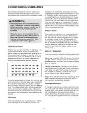
... pulse sensor is near the middle number in your goal is to five workouts each week, with pre-existing health problems. During the first few minutes of exercise does your cardiovascular system, the key to achieving the desired results is to use stored fat calories for energy. For aerobic exercise, adjust the intensity of your exercise until your heart rate is not a medical device. Training...
... pulse sensor is near the middle number in your goal is to five workouts each week, with pre-existing health problems. During the first few minutes of exercise does your cardiovascular system, the key to achieving the desired results is to use stored fat calories for energy. For aerobic exercise, adjust the intensity of your exercise until your heart rate is not a medical device. Training...
Uk Manual
Page 14
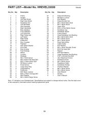
See the back cover of this manual for information about ordering replacement parts. 14 Qty. Description Key No. Specifications are subject to change without notice. Qty. HREVEL33030 R0903A Key No. PART LIST-Model No. Description 1 1 Frame 2 1 Upright 3 1 Left Side Shield 4 1 Right Side Shield 5 2 Handlebar Arm 6 1 Left Handlebar 7 1 Idler Assembly 8 1 Right Handlebar 9 1 Rear Stabiliser 10 1 Front Stabiliser 11 1 Left Pedal Arm 12 1 Right Pedal Arm 13 1 Left Pedal 14 1 Right Pedal 15 2 Pedal Disc 16...
See the back cover of this manual for information about ordering replacement parts. 14 Qty. Description Key No. Specifications are subject to change without notice. Qty. HREVEL33030 R0903A Key No. PART LIST-Model No. Description 1 1 Frame 2 1 Upright 3 1 Left Side Shield 4 1 Right Side Shield 5 2 Handlebar Arm 6 1 Left Handlebar 7 1 Idler Assembly 8 1 Right Handlebar 9 1 Rear Stabiliser 10 1 Front Stabiliser 11 1 Left Pedal Arm 12 1 Right Pedal Arm 13 1 Left Pedal 14 1 Right Pedal 15 2 Pedal Disc 16...
Uk Manual
Page 15
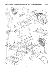
EXPLODED DRAWING-Model No. HREVEL33030 R0903A 23 63 66 8 24 29 64 52 52 68 52 52 4 66 6 55 46 49 50 56 5 45 59 44 48 38 47 49 33 65 22 41 59 45 49 47 38 55 56 46 49 50 3 52 68 52 64 48 2 5 40 14 40 59 27 60 59 60 17 33 58 39 57 12 35 38 51 36 16 37 37 36 69 15 22 60 41 21 28 34 21 10 52 33 54 53 61 13 51 40 69 51 67 26 7 33 25 5442 38 31 32 30 31 30 33 1 62 16 33 61 9 34 51 69 18 52 20 11 69 15 20 19 40 36 37 38 35 36 15
EXPLODED DRAWING-Model No. HREVEL33030 R0903A 23 63 66 8 24 29 64 52 52 68 52 52 4 66 6 55 46 49 50 56 5 45 59 44 48 38 47 49 33 65 22 41 59 45 49 47 38 55 56 46 49 50 3 52 68 52 64 48 2 5 40 14 40 59 27 60 59 60 17 33 58 39 57 12 35 38 51 36 16 37 37 36 69 15 22 60 41 21 28 34 21 10 52 33 54 53 61 13 51 40 69 51 67 26 7 33 25 5442 38 31 32 30 31 30 33 1 62 16 33 61 9 34 51 69 18 52 20 11 69 15 20 19 40 36 37 38 35 36 15
Uk Manual
Page 16
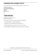
... prepared to give the following information: • the MODEL NUMBER of the product (HREVEL33030) • the NAME of the product (HealthRider® 690 S elliptical trainer) • the SERIAL NUMBER of the product (see the front cover of this manual) • the KEY NUMBER and DESCRIPTION of the part(s) (see page 14 of this manual) HealthRider is a registered trademark of ICON Health & Fitness, Inc. ORDERING REPLACEMENT PARTS To order replacement parts, contact the ICON Health & Fitness, Ltd.
... prepared to give the following information: • the MODEL NUMBER of the product (HREVEL33030) • the NAME of the product (HealthRider® 690 S elliptical trainer) • the SERIAL NUMBER of the product (see the front cover of this manual) • the KEY NUMBER and DESCRIPTION of the part(s) (see page 14 of this manual) HealthRider is a registered trademark of ICON Health & Fitness, Inc. ORDERING REPLACEMENT PARTS To order replacement parts, contact the ICON Health & Fitness, Ltd.


