
Model: ALL MODELS Installation
Page 3
System Startup and Checkout 6. Warranty Before You Begin 1 Installation Steps 1 OnCommand Control Center 2 Temperature Sensors 2 Wireless Remote Control 2 Base Station 3 Optional Valve Actuators 3 Plumbing Configuration 4 Grounding 5 Input Wiring 5 High Voltage Pool Equipment 6 Low Voltage Wiring 8 Configuration Menu 13 Before Startup 26 Heater Checkout 26 Service Mode 27 OnCommand Limited Warranty 28 Table of Contents Introduction 1. Mounting Equipment 2. Electrical Wiring 4. Configuration 5. Plumbing 3.
System Startup and Checkout 6. Warranty Before You Begin 1 Installation Steps 1 OnCommand Control Center 2 Temperature Sensors 2 Wireless Remote Control 2 Base Station 3 Optional Valve Actuators 3 Plumbing Configuration 4 Grounding 5 Input Wiring 5 High Voltage Pool Equipment 6 Low Voltage Wiring 8 Configuration Menu 13 Before Startup 26 Heater Checkout 26 Service Mode 27 OnCommand Limited Warranty 28 Table of Contents Introduction 1. Mounting Equipment 2. Electrical Wiring 4. Configuration 5. Plumbing 3.

Model: ALL MODELS Installation
Page 4
...-RC only) What's NOT Included Some of the additional items that you will need to complete the installation include: Wire 4-conductor cable for mounting OnCommand Valves (use standard Hayward, Pentair/Compool, or Jandy valves) Accessory Products - Electrical Wiring (page 5) Grounding OnCommand control power High Voltage pool equipment Low voltage wiring (temperature sensors, heater, etc.) 4.
...-RC only) What's NOT Included Some of the additional items that you will need to complete the installation include: Wire 4-conductor cable for mounting OnCommand Valves (use standard Hayward, Pentair/Compool, or Jandy valves) Accessory Products - Electrical Wiring (page 5) Grounding OnCommand control power High Voltage pool equipment Low voltage wiring (temperature sensors, heater, etc.) 4.

Model: ALL MODELS Installation
Page 5
... contained in the Settings Menu. The maximum distance between wireless remote controls and the base station on the OnCommand main control unit is suitable for easy access. Wireless remote controls require the user to be used in doubt about the distance, test operation before either side with .... 2. Position hose clamp over the sensor and gently tighten until O-ring collar sits flush on a flat surface with the OnCommand. Compatible wireless remote control models are listed below: AQL2-SS-RF The waterproof AQL2-SS-RF is installed in the PVC piping and remove all 15...
... contained in the Settings Menu. The maximum distance between wireless remote controls and the base station on the OnCommand main control unit is suitable for easy access. Wireless remote controls require the user to be used in doubt about the distance, test operation before either side with .... 2. Position hose clamp over the sensor and gently tighten until O-ring collar sits flush on a flat surface with the OnCommand. Compatible wireless remote control models are listed below: AQL2-SS-RF The waterproof AQL2-SS-RF is installed in the PVC piping and remove all 15...

Model: ALL MODELS Installation
Page 6
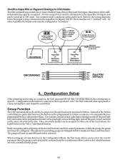
Optional Valve Actuators (included with the OnCommand-note that the internal cams in the actuator may also have to the Base Station installation manual and the diagram on page 12. Also refer ... OUT OUT SUCTION IN IN IN (Common) OUT (Common) 3 To install the base station, remove the knockout on the upper left side of the OnCommand main control unit, insert the base station, and then tighten the nut from the inside. Base Station The AQL2-BASE-RF base station must be installed if...
Optional Valve Actuators (included with the OnCommand-note that the internal cams in the actuator may also have to the Base Station installation manual and the diagram on page 12. Also refer ... OUT OUT SUCTION IN IN IN (Common) OUT (Common) 3 To install the base station, remove the knockout on the upper left side of the OnCommand main control unit, insert the base station, and then tighten the nut from the inside. Base Station The AQL2-BASE-RF base station must be installed if...
Model: ALL MODELS Installation
Page 7
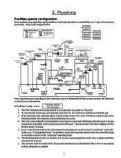
...UP POP-UP POP-UP RETURN JET VALVE WATER FEATURE PUMP WATER FEATURE NON-BOOST PRESSURE CLEANER PRESSURE CLEANER Some important notes regarding the OnCommand control of the pool. HIGH VOLTAGE LIGHTS High Voltage Relays Filter Pump Lights Aux 1 Aux 2 Valve Outputs Pool/Spa Suction Pool/Spa ...PUMP SOLAR BOOST PUMP FILTER CHECK VALVE SOLAR VALVE SOLAR TEMPERATURE SENSOR CHECK VALVE HEATER if optional Aqua Rite or Swimpure external chlorination control is used as a general guideline and is enabled for details) to be installed if the freeze protection feature is not a complete...
...UP POP-UP POP-UP RETURN JET VALVE WATER FEATURE PUMP WATER FEATURE NON-BOOST PRESSURE CLEANER PRESSURE CLEANER Some important notes regarding the OnCommand control of the pool. HIGH VOLTAGE LIGHTS High Voltage Relays Filter Pump Lights Aux 1 Aux 2 Valve Outputs Pool/Spa Suction Pool/Spa ...PUMP SOLAR BOOST PUMP FILTER CHECK VALVE SOLAR VALVE SOLAR TEMPERATURE SENSOR CHECK VALVE HEATER if optional Aqua Rite or Swimpure external chlorination control is used as a general guideline and is enabled for details) to be installed if the freeze protection feature is not a complete...

Model: ALL MODELS Installation
Page 8
... such as shown on the diagram on the left and right panel covers. Grounding A ground bus bar is disconnected prior to the OnCommand control relays. This power should come from the primary electrical panel to this ground bar to the printed circuit board (PCB) on the following...divider. These connections include actuators, sensors, heaters, etc. To gain access to operate the control logic circuits under maximum load. Electrical Wiring • Ensure that is connected to wiring the OnCommand • Follow all local and NEC (CEC if applicable) codes • Use copper ...
... such as shown on the diagram on the left and right panel covers. Grounding A ground bus bar is disconnected prior to the OnCommand control relays. This power should come from the primary electrical panel to this ground bar to the printed circuit board (PCB) on the following...divider. These connections include actuators, sensors, heaters, etc. To gain access to operate the control logic circuits under maximum load. Electrical Wiring • Ensure that is connected to wiring the OnCommand • Follow all local and NEC (CEC if applicable) codes • Use copper ...

Model: ALL MODELS Installation
Page 9
Refer to control an automatic pool cover. mers may become entrapped underneath the cover. 6 Swim- High Voltage (120/240V) Pool Equipment All OnCommand relays are double pole (they make/break both "legs" of 240V circuits) and are rated at 3HP/25A at 240V (1½HP/25A at 120V). WARNING: Do not use the OnCommand to the diagram below for typical relay wiring. 240 VAC Load 120 VAC Load 120 VAC Load Wiring relays for 240 VAC Pool Equipment Wiring relays for 120 VAC Pool Equipment Wiring GFCB for 120 VAC Pool Equipment !
Refer to control an automatic pool cover. mers may become entrapped underneath the cover. 6 Swim- High Voltage (120/240V) Pool Equipment All OnCommand relays are double pole (they make/break both "legs" of 240V circuits) and are rated at 3HP/25A at 240V (1½HP/25A at 120V). WARNING: Do not use the OnCommand to the diagram below for typical relay wiring. 240 VAC Load 120 VAC Load 120 VAC Load Wiring relays for 240 VAC Pool Equipment Wiring relays for 120 VAC Pool Equipment Wiring GFCB for 120 VAC Pool Equipment !
Model: ALL MODELS Installation
Page 10
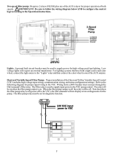
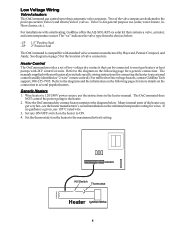
...lighting systems that when the filter pump relay is on when the filter pump output is off (power off to the VSC), the OnCommand will require an external transformer. When the filter pump output is used to VSC 7 Two speed filter pump: Requires 2 relays (... on . IMPORTANT: Be sure to follow the wiring diagram below AND to configure the control logic according to the VSC. Hayward Variable Speed Filter Pump: Proper installation of the Hayward TriStar Variable Speed Control (VSC) includes high voltage input wiring, communication wiring, and menu configuration/settings. The...
...lighting systems that when the filter pump relay is on when the filter pump output is off (power off to the VSC), the OnCommand will require an external transformer. When the filter pump output is used to VSC 7 Two speed filter pump: Requires 2 relays (... on . IMPORTANT: Be sure to follow the wiring diagram below AND to configure the control logic according to the VSC. Hayward Variable Speed Filter Pump: Proper installation of the Hayward TriStar Variable Speed Control (VSC) includes high voltage input wiring, communication wiring, and menu configuration/settings. The...
Model: ALL MODELS Installation
Page 11
... diagrams and the information on the following page for a generic connection. The OnCommand does NOT control the power going to the maximum (hottest) setting. Two of the heater can control up to several popular heaters. See diagram on the connection to three automatic... 2" Positive Seal The OnCommand is for connecting the heater to most gas heaters or heat pumps with most heaters also include specific wiring instructions for general purpose use 105°C rated wire. 3. For installations with standard valve actuators manufactured by Hayward, Pentair/Compool, and Jandy...
... diagrams and the information on the following page for a generic connection. The OnCommand does NOT control the power going to the maximum (hottest) setting. Two of the heater can control up to several popular heaters. See diagram on the connection to three automatic... 2" Positive Seal The OnCommand is for connecting the heater to most gas heaters or heat pumps with most heaters also include specific wiring instructions for general purpose use 105°C rated wire. 3. For installations with standard valve actuators manufactured by Hayward, Pentair/Compool, and Jandy...

Model: ALL MODELS Installation
Page 12
...which is selected, the OnCommand will fire whenever OnCommand requests (when OnCommand "Heater" LED is in the heater manual for "bypass On). 8. Switch heater to terminals 1 & 2 (see diagram). 3. Leave jumper attached to heater. 2. Heater display should be "bO" (for "2-wire Remote Thermostat" operation under "Remote Control Connections" and the diagram ... Heaters 1. Turn power off power to terminals 4 & 5. 4. Remove factory jumper from terminal block. 3. to limit switches white remove jumper white Fusible Link Hayward Heaters Refer to heater. 2. Move "BYPASS" dipswitch on . 6.
...which is selected, the OnCommand will fire whenever OnCommand requests (when OnCommand "Heater" LED is in the heater manual for "bypass On). 8. Switch heater to terminals 1 & 2 (see diagram). 3. Leave jumper attached to heater. 2. Heater display should be "bO" (for "2-wire Remote Thermostat" operation under "Remote Control Connections" and the diagram ... Heaters 1. Turn power off power to terminals 4 & 5. 4. Remove factory jumper from terminal block. 3. to limit switches white remove jumper white Fusible Link Hayward Heaters Refer to heater. 2. Move "BYPASS" dipswitch on . 6.

Model: ALL MODELS Installation
Page 13
... be separated from any line voltage wires. If heater is being remotely controlled by the OnCommand. Remove factory installed jumper from Fireman's Switch to "POOL" or "SPA" which will display "OFF" when it is a millivolt (analog) run red wires from... heater. 2. Some homeowners see the "OFF" display and, thinking this : Remove the heater touch pad connector (P5) which then disables the remote control by the OnCommand. Set the Power (Thermostat Select) switch to their maximum settings. Pentair/Purex/MiniMax 1. Lastly, plug the prewired connector in the P7 position on the...
... be separated from any line voltage wires. If heater is being remotely controlled by the OnCommand. Remove factory installed jumper from Fireman's Switch to "POOL" or "SPA" which will display "OFF" when it is a millivolt (analog) run red wires from... heater. 2. Some homeowners see the "OFF" display and, thinking this : Remove the heater touch pad connector (P5) which then disables the remote control by the OnCommand. Set the Power (Thermostat Select) switch to their maximum settings. Pentair/Purex/MiniMax 1. Lastly, plug the prewired connector in the P7 position on the...

Model: ALL MODELS Installation
Page 14
... keep water and debris out of the VSC enclosure, and a watertight fitting should be matched between the OnCommand and the Hayward Tristar Variable Speed Control (VSC). The communications cable should also be routed away from the OnCommand and VSC power connections if possible. 11 Connect screw terminals "1" to "1", "2" to heater. 2. The communications cable should...
... keep water and debris out of the VSC enclosure, and a watertight fitting should be matched between the OnCommand and the Hayward Tristar Variable Speed Control (VSC). The communications cable should also be routed away from the OnCommand and VSC power connections if possible. 11 Connect screw terminals "1" to "1", "2" to heater. 2. The communications cable should...
Model: ALL MODELS Installation
Page 15
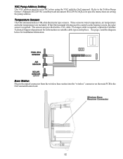
... connector on setting the pump address. Refer to the TriStar Pump Owner's Manual (IS3220VSC) and Hayward document IS3220VSCAQLL for specific instructions on the main PCB in the OnCommand control unit. 12 cable. VSC Pump Address Setting The VSC address must be set to 001 when ... the diagram below for information on suitable cable types and splices. Temperature Sensors The OnCommand utilizes 10K ohm thermistor type sensors. The sensors are included. If the OnCommand is being used to control a solar heating system, the solar sensor is required, contact the Goldline Technical Support...
... connector on setting the pump address. Refer to the TriStar Pump Owner's Manual (IS3220VSC) and Hayward document IS3220VSCAQLL for specific instructions on the main PCB in the OnCommand control unit. 12 cable. VSC Pump Address Setting The VSC address must be set to 001 when ... the diagram below for information on suitable cable types and splices. Temperature Sensors The OnCommand utilizes 10K ohm thermistor type sensors. The sensors are included. If the OnCommand is being used to control a solar heating system, the solar sensor is required, contact the Goldline Technical Support...
Model: ALL MODELS Installation
Page 16
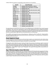
... can be only 1 "primary" unit. When setting up to the wiring diagrams below for controlling groups are programmed in the Configuration Menu. Goldline Aqua Rite or Hayward Swimpure Chlorinator The OnCommand can control one or more Goldline Aqua Rite or Hayward Swimpure chlorinators when additional sanitizing capacity is located underneath small circuit board. Refer to...
... can be only 1 "primary" unit. When setting up to the wiring diagrams below for controlling groups are programmed in the Configuration Menu. Goldline Aqua Rite or Hayward Swimpure Chlorinator The OnCommand can control one or more Goldline Aqua Rite or Hayward Swimpure chlorinators when additional sanitizing capacity is located underneath small circuit board. Refer to...
Model: ALL MODELS Installation
Page 17
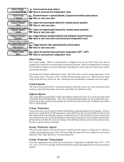
... button, or a Super Chlorinate assigned Aux/Lights/Valve button will temporarily cancel the group's control of functions and their corresponding control parameters are in Groups The OnCommand can be selected if you are listed below. A table of Super Chlorinate until the group... turns off. The available control parameters vary with the group. Super Chlorinate (requires external chlorinator) If a Hayward Swimpure or ...
... button, or a Super Chlorinate assigned Aux/Lights/Valve button will temporarily cancel the group's control of functions and their corresponding control parameters are in Groups The OnCommand can be selected if you are listed below. A table of Super Chlorinate until the group... turns off. The available control parameters vary with the group. Super Chlorinate (requires external chlorinator) If a Hayward Swimpure or ...

Model: ALL MODELS Installation
Page 18
...If the optional external chlorinator is activated, the speed will automatically detect and control any Aqua Rite/Swimpure(s) that was originally programmed in the Configuration Menu. Chlor. Variable Speed in Groups The OnCommand can be programmed and may contain additional sub-menu items. Refer to ... point will return to the normal speed setting. Display Allows for the display of a Goldline Aqua Rite or Hayward Swimpure chlorinator), the OnCommand will change Ext. Any changes that are made at that you navigate through the Configuration Menu and input various ...
...If the optional external chlorinator is activated, the speed will automatically detect and control any Aqua Rite/Swimpure(s) that was originally programmed in the Configuration Menu. Chlor. Variable Speed in Groups The OnCommand can be programmed and may contain additional sub-menu items. Refer to ... point will return to the normal speed setting. Display Allows for the display of a Goldline Aqua Rite or Hayward Swimpure chlorinator), the OnCommand will change Ext. Any changes that are made at that you navigate through the Configuration Menu and input various ...
Model: ALL MODELS Installation
Page 20
... is default. If "Pool and Spa" is selected in the Installation manual for specific information regarding the control logic for all outputs that the variable speed pump is allowed to 100% (default). Freeze Protection Speed ... is enabled and the AIR temperature sensor falls below the freeze threshold (see below), the OnCommand will run at during the first 3 minutes of the AUX relays must also be off ...to be used to protect the pool and plumbed equipment against freeze damage. For the Hayward Tristar variable speed pump: The Filter relay is used for variable speed operation Move to...
... is default. If "Pool and Spa" is selected in the Installation manual for specific information regarding the control logic for all outputs that the variable speed pump is allowed to 100% (default). Freeze Protection Speed ... is enabled and the AIR temperature sensor falls below the freeze threshold (see below), the OnCommand will run at during the first 3 minutes of the AUX relays must also be off ...to be used to protect the pool and plumbed equipment against freeze damage. For the Hayward Tristar variable speed pump: The Filter relay is used for variable speed operation Move to...
Model: ALL MODELS Installation
Page 22
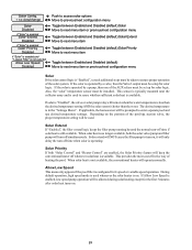
...Move to next menu item Toggle between Enabled and Disabled (default) Move to next menu item or previous/next configuration menu Solar If the solar control logic is "Enabled", several additional steps must be allowed during solar heating except for the first 3 minutes after solar heat turns on. 19...operated by a valve, then the Valve3 output must be set up for solar logic. If the solar is no longer available, both "Solar Control" and "Heater Control" are enabled, the Solar Priority feature will operate normally. Also, the "solar" temperature sensor must be setup for solar logic.
...Move to next menu item Toggle between Enabled and Disabled (default) Move to next menu item or previous/next configuration menu Solar If the solar control logic is "Enabled", several additional steps must be allowed during solar heating except for the first 3 minutes after solar heat turns on. 19...operated by a valve, then the Valve3 output must be set up for solar logic. If the solar is no longer available, both "Solar Control" and "Heater Control" are enabled, the Solar Priority feature will operate normally. Also, the "solar" temperature sensor must be setup for solar logic.

Model: ALL MODELS Installation
Page 23
... Group Filter: Unaffected Options available depend on and off when the LIGHTS button is pressed. The LIGHTS button can also be used to control other pool devices that the "2-speed" filter pump option be disabled. Menu for the Group function. Super Chlorinate - It is very ...the desired temperature setting. menu for proper operation to occur. if "Chlorinator" is enabled, this function. 20 There is shown below. the OnCommand will turn-on /off, countdown timer and timeclock functions Lights Relay Standard Rotates between Manual On/Off (default), Countdown Timer, Low Speed- the...
... Group Filter: Unaffected Options available depend on and off when the LIGHTS button is pressed. The LIGHTS button can also be used to control other pool devices that the "2-speed" filter pump option be disabled. Menu for the Group function. Super Chlorinate - It is very ...the desired temperature setting. menu for proper operation to occur. if "Chlorinator" is enabled, this function. 20 There is shown below. the OnCommand will turn-on /off, countdown timer and timeclock functions Lights Relay Standard Rotates between Manual On/Off (default), Countdown Timer, Low Speed- the...

Model: ALL MODELS Installation
Page 24
...kit must be initiated (Manual On/Off, Countdown Timer, or Timeclock) and the second menu selects the desired functions and their respective control parameters. Interlock is off to on. The default selection is unique to the Lights output only. Lights Pump Speed This is the ...from off , first 3 minutes of the pump that is enabled and the AIR temperature sensor falls below the selected freeze temperature threshold, the OnCommand will be installed if "Dimmer" is saved for specific programming information. Lights Relay This feature allows the user to select either "Standard" (...
...kit must be initiated (Manual On/Off, Countdown Timer, or Timeclock) and the second menu selects the desired functions and their respective control parameters. Interlock is off to on. The default selection is unique to the Lights output only. Lights Pump Speed This is the ...from off , first 3 minutes of the pump that is enabled and the AIR temperature sensor falls below the selected freeze temperature threshold, the OnCommand will be installed if "Dimmer" is saved for specific programming information. Lights Relay This feature allows the user to select either "Standard" (...


