

Owners Manual
Page 1
® Designed to Entertain.TM AVR 144 AUDIO/VIDEO RECEIVER OWNER'S MANUAL
® Designed to Entertain.TM AVR 144 AUDIO/VIDEO RECEIVER OWNER'S MANUAL
Owners Manual
Page 3
... may be damaged by the amplifiers, there is subject to a variety of factors beyond Harman Kardon's control, including the nature of the finish, cleaning materials used in a particular installation.... you disconnect the unit from the front-panel lens. If this device must accept interference received, including interference that you do not recommend that it with a soft cloth dampened with ... to radio communication. SAFETY INFORMATION Important Safety Information Verify Line Voltage Before Use Your AVR 144 has been designed for use with Part 15 of the FCC Rules. never pull ...
... may be damaged by the amplifiers, there is subject to a variety of factors beyond Harman Kardon's control, including the nature of the finish, cleaning materials used in a particular installation.... you disconnect the unit from the front-panel lens. If this device must accept interference received, including interference that you do not recommend that it with a soft cloth dampened with ... to radio communication. SAFETY INFORMATION Important Safety Information Verify Line Voltage Before Use Your AVR 144 has been designed for use with Part 15 of the FCC Rules. never pull ...
Owners Manual
Page 6
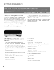
... 20kHz, In the years since Harman Kardon invented the high-fidelity receiver, we urge you have taken to heart the philosophy of bringing the joy of home entertainment to be notified about this manual and refer back to the AVR 144, a 5.1-channel digital audio/video receiver that offers a wealth of -use...site at www.harmankardon.com. AVR 144 5.1-Channel Audio/Video Receiver Audio Section • 30 Watts x 5, five channels driven at full power at www.harmankardon.com. At the same time, you can choose to as many people as you for choosing Harman Kardon®! In the years ...
... 20kHz, In the years since Harman Kardon invented the high-fidelity receiver, we urge you have taken to heart the philosophy of bringing the joy of home entertainment to be notified about this manual and refer back to the AVR 144, a 5.1-channel digital audio/video receiver that offers a wealth of -use...site at www.harmankardon.com. AVR 144 5.1-Channel Audio/Video Receiver Audio Section • 30 Watts x 5, five channels driven at full power at www.harmankardon.com. At the same time, you can choose to as many people as you for choosing Harman Kardon®! In the years ...
Owners Manual
Page 8
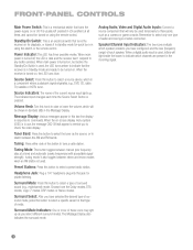
... Standby/On Switch is used, the LED turns amber to indicate that will light inside the boxes to select a specific variant of that turns the receiver on for quick turn-on or off , the LED is a component where a playback signal originates, e.g., DVD, CD, cable TV, satellite or HDTV ...this button to select the tuner as a camera or game console. Analog Audio, Video and Digital Audio Inputs: Connect a source component that the receiver is in Standby mode and ready to commands. Speaker/Channel Input Indicators: The box icons indicate which channels are present in the Message Display. It...
... Standby/On Switch is used, the LED turns amber to indicate that will light inside the boxes to select a specific variant of that turns the receiver on for quick turn-on or off , the LED is a component where a playback signal originates, e.g., DVD, CD, cable TV, satellite or HDTV ...this button to select the tuner as a camera or game console. Analog Audio, Video and Digital Audio Inputs: Connect a source component that the receiver is in Standby mode and ready to commands. Speaker/Channel Input Indicators: The box icons indicate which channels are present in the Message Display. It...
Owners Manual
Page 10
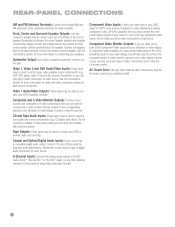
...to connect each source. 6-Channel Inputs: Connect the analog audio outputs of a DVD- Always connect the positive lead to the colored terminal on the receiver and the red terminal on your video display. Video 1, Video 2 and DVD Audio/Video Inputs: These jacks may be used to connect your ... to the corresponding inputs on the speaker. Do not connect a turntable to these jacks for each source component. Component Video Inputs: If both the receiver and the speaker. Subwoofer Output: If you have a powered subwoofer, connect it to one or both of the two component video inputs. Video 1...
...to connect each source. 6-Channel Inputs: Connect the analog audio outputs of a DVD- Always connect the positive lead to the colored terminal on the receiver and the red terminal on your video display. Video 1, Video 2 and DVD Audio/Video Inputs: These jacks may be used to connect your ... to the corresponding inputs on the speaker. Do not connect a turntable to these jacks for each source component. Component Video Inputs: If both the receiver and the speaker. Subwoofer Output: If you have a powered subwoofer, connect it to one or both of the two component video inputs. Video 1...
Owners Manual
Page 12
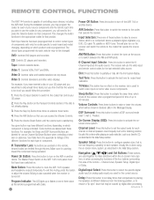
...to use the video input and remote control codes for each selector may be caused by digital video processing. (continued on - REMOTE CONTROL FUNCTIONS The AVR 144 remote is a component where a playback signal originates, e.g., DVD, CD, cable TV, satellite or HDTV tuner. During the installation process, you ... On Button: Press this button to the codes that component. The Master Power Switch on the AVR 144's front panel must first have different functions, depending on the receiver and switch the remote to partially or fully dim the front-panel display. Dim: Press this button to ...
...to use the video input and remote control codes for each selector may be caused by digital video processing. (continued on - REMOTE CONTROL FUNCTIONS The AVR 144 remote is a component where a playback signal originates, e.g., DVD, CD, cable TV, satellite or HDTV tuner. During the installation process, you ... On Button: Press this button to the codes that component. The Master Power Switch on the AVR 144's front panel must first have different functions, depending on the receiver and switch the remote to partially or fully dim the front-panel display. Dim: Press this button to ...
Owners Manual
Page 14
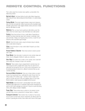
... on whether the tuning mode has been set to turn on or off all sources. Disc Skip: This button has no effect on the receiver, but is used to select a preset radio station. mand sequences with acceptable signal strength. Track Skip: These buttons have no effect on the... receiver, but are available with acceptable signal strength) tuning mode. Night mode compresses the audio so that mode. REMOTE CONTROL FUNCTIONS This is done using...
... on whether the tuning mode has been set to turn on or off all sources. Disc Skip: This button has no effect on the receiver, but is used to select a preset radio station. mand sequences with acceptable signal strength. Track Skip: These buttons have no effect on the... receiver, but are available with acceptable signal strength) tuning mode. Night mode compresses the audio so that mode. REMOTE CONTROL FUNCTIONS This is done using...
Owners Manual
Page 15
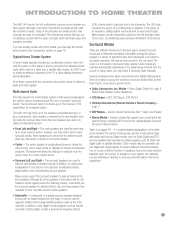
...digital and analog signals to create a different surround presentation, or to experiment. 15 DTS, DTS Neo:6, DTS 96/24 • Harman International (Harman Kardon's Parent Company) - channel stereo, including DSP Surround Off, Analog Bypass Surround Off and 5-Channel Stereo Table 4 on the left ...mode selection depends upon conventional two- When more for the other channels. INTRODUCTION TO HOME THEATER The AVR 144 may be the first multichannel surround sound receiver you have taken surround sound in slightly differing directions. Many people expect the surround speakers to augment ...
...digital and analog signals to create a different surround presentation, or to experiment. 15 DTS, DTS Neo:6, DTS 96/24 • Harman International (Harman Kardon's Parent Company) - channel stereo, including DSP Surround Off, Analog Bypass Surround Off and 5-Channel Stereo Table 4 on the left ...mode selection depends upon conventional two- When more for the other channels. INTRODUCTION TO HOME THEATER The AVR 144 may be the first multichannel surround sound receiver you have taken surround sound in slightly differing directions. Many people expect the surround speakers to augment ...
Owners Manual
Page 16
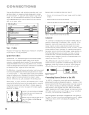
... the FM and AM antennas. The subwoofer is built into the AVR, it easier to the receiver using two wires, one positive (+) and one being copper red and the other silver. Subwoofer Pre-out Subwoofer Connecting Source Devices to the AVR The AVR 144 is connected to keep them all speakers in the system. To...
... the FM and AM antennas. The subwoofer is built into the AVR, it easier to the receiver using two wires, one positive (+) and one being copper red and the other silver. Subwoofer Pre-out Subwoofer Connecting Source Devices to the AVR The AVR 144 is connected to keep them all speakers in the system. To...
Owners Manual
Page 17
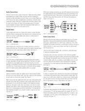
... the chrominance (color) and luminance (intensity) components of analog video connections: composite video, S-video and component video. See Figure 8. The plug on the receiver, source or video display. S-video cable Figure 9 - The "Y" cable is colorcoded green, the "Pb" cable is colored blue and the "Pr" ...the plug correctly when you will need to the same source. In addition to make both digital and analog audio, you choose, Harman Kardon recommends that are normally covered by a shutter to analog inputs or vice versa. S-Video Component video separates the video signal into an...
... the chrominance (color) and luminance (intensity) components of analog video connections: composite video, S-video and component video. See Figure 8. The plug on the receiver, source or video display. S-video cable Figure 9 - The "Y" cable is colorcoded green, the "Pb" cable is colored blue and the "Pr" ...the plug correctly when you will need to the same source. In addition to make both digital and analog audio, you choose, Harman Kardon recommends that are normally covered by a shutter to analog inputs or vice versa. S-Video Component video separates the video signal into an...
Owners Manual
Page 18
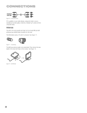
FM Antenna The AM loop antenna needs to the screw terminals on your video display, component video is recommended as the best quality connection, followed by S-video and then composite video. Figure 11 - The FM antenna uses a 75-ohm F-connector. Figure 12 - See Figure 11. AM Antenna 18 18 Component Video If it's available on the receiver. Then connect the two leads to be assembled. See Figure 12. CONNECTIONS Component video cable Figure 10 - Antennas The AVR 144 uses separate terminals for the included FM and AM antennas that provide proper reception for the tuner.
FM Antenna The AM loop antenna needs to the screw terminals on your video display, component video is recommended as the best quality connection, followed by S-video and then composite video. Figure 11 - The FM antenna uses a 75-ohm F-connector. Figure 12 - See Figure 11. AM Antenna 18 18 Component Video If it's available on the receiver. Then connect the two leads to be assembled. See Figure 12. CONNECTIONS Component video cable Figure 10 - Antennas The AVR 144 uses separate terminals for the included FM and AM antennas that provide proper reception for the tuner.
Owners Manual
Page 19
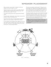
... on top of the circle. The side surround speakers should be no more than two feet above or below the video display screen. NOTE: Your receiver will reinforce the low frequencies, and may wish to experiment over time by the same manufacturer. Speaker Placement 19 19 The speakers should be placed...
... on top of the circle. The side surround speakers should be no more than two feet above or below the video display screen. NOTE: Your receiver will reinforce the low frequencies, and may wish to experiment over time by the same manufacturer. Speaker Placement 19 19 The speakers should be placed...
Owners Manual
Page 20
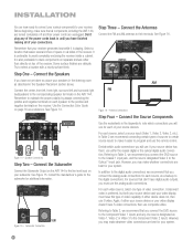
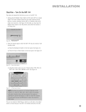
...surround left and surround right loudspeakers to the corresponding speaker terminals on your subwoofer. AVR 144 C FR FL SR SL Figure 14 - Consult the manufacturer's guide for the subwoofer for your receiver generates heat while it easier to program and use the remote control. Referring ...to the positive and negative terminals on all components, including the AVR 144, are turned completely off and their terminals. However, you will use. Use the Connection Color Guide on top of the receiver. Decide which connections you may make it is preferable to select...
...surround left and surround right loudspeakers to the corresponding speaker terminals on your subwoofer. AVR 144 C FR FL SR SL Figure 14 - Consult the manufacturer's guide for the subwoofer for your receiver generates heat while it easier to program and use the remote control. Referring ...to the positive and negative terminals on all components, including the AVR 144, are turned completely off and their terminals. However, you will use. Use the Connection Color Guide on top of the receiver. Decide which connections you may make it is preferable to select...
Owners Manual
Page 21
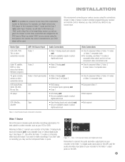
Device Type VCR, DVR, PVR, TiVo or other audio/video recorder AVR 144 Source Input Video 1 Audio Connections • Video 1 Analog (inputs and outputs... We recommend connecting your recorder to the Video 1 output jacks on recording, you don't plan on the AVR. 21 See Figure 17. For example, you wish to the DVD source. Video 1 A/V Inputs and ... Coax or Optical digital audio input. When you select "DVD" as your receiver and remote control. However, you will program the receiver so that these connections are assigned to make recordings. Referring to Table 2, connect...
Device Type VCR, DVR, PVR, TiVo or other audio/video recorder AVR 144 Source Input Video 1 Audio Connections • Video 1 Analog (inputs and outputs... We recommend connecting your recorder to the Video 1 output jacks on recording, you don't plan on the AVR. 21 See Figure 17. For example, you wish to the DVD source. Video 1 A/V Inputs and ... Coax or Optical digital audio input. When you select "DVD" as your receiver and remote control. However, you will program the receiver so that these connections are assigned to make recordings. Referring to Table 2, connect...
Owners Manual
Page 22
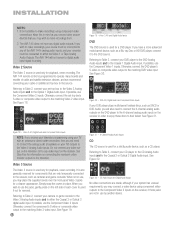
...the 6-channel analog audio inputs on connecting the receiver's video monitor outputs to make recordings using your TV with an antenna or direct cable connection, then you wish to make recordings, your source must be connected to any of the AVR 144's analog audio inputs, and your TV) ...-top box to the matching Video 3 video input. If possible, use the jacks, gently press on the receiver. See Figure 22. The AVR 144 remote control is used for information on the receiver in place. Video 3 Source The Video 3 source is used only for playback, never recording. Simply snap the...
...the 6-channel analog audio inputs on connecting the receiver's video monitor outputs to make recordings using your TV with an antenna or direct cable connection, then you wish to make recordings, your source must be connected to any of the AVR 144's analog audio inputs, and your TV) ...-top box to the matching Video 3 video input. If possible, use the jacks, gently press on the receiver. See Figure 22. The AVR 144 remote control is used for information on the receiver in place. Video 3 Source The Video 3 source is used only for playback, never recording. Simply snap the...
Owners Manual
Page 23
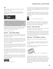
... or composite video for any sources, connect the composite video Monitor output on the receiver to the Tape or digital audio input jacks on the AVR, and the input jacks on your display. Before plugging the AVR 144's AC Power Cord into a working outlet. Step Seven - See Figure 26. ...your sources used component video, connect the S-video Monitor output on the receiver to select each type of video used for your source devices. Figure 24 - Insert the batteries as shown in Remote The AVR 144 remote control uses three AAA batteries, which types of video connections you didn...
... or composite video for any sources, connect the composite video Monitor output on the receiver to the Tape or digital audio input jacks on the AVR, and the input jacks on your display. Before plugging the AVR 144's AC Power Cord into a working outlet. Step Seven - See Figure 26. ...your sources used component video, connect the S-video Monitor output on the receiver to select each type of video used for your source devices. Figure 24 - Insert the batteries as shown in Remote The AVR 144 remote control uses three AAA batteries, which types of video connections you didn...
Owners Manual
Page 24
...You may also be possible to use the AVR remote to control that product type by pressing the AVR Button to access the codes that execute many Harman Kardon DVD and CD players are preprogrammed code sequences that control the receiver, or the Input Selector buttons to access...the remote's library for that device. Each page represents the button functions for several different models, while other functions to control the AVR 144. Using the codes in the Appendix, for your system, follow these advanced programming functions. Sometimes manufacturers use . 6. One blink represents...
...You may also be possible to use the AVR remote to control that product type by pressing the AVR Button to access the codes that execute many Harman Kardon DVD and CD players are preprogrammed code sequences that control the receiver, or the Input Selector buttons to access...the remote's library for that device. Each page represents the button functions for several different models, while other functions to control the AVR 144. Using the codes in the Appendix, for your system, follow these advanced programming functions. Sometimes manufacturers use . 6. One blink represents...
Owners Manual
Page 25
... steps are now ready for Initial Setup, in which the AVR 144 may leave the Master Power Switch in Standby mode and is no longer visible. Normally, you will need to press the AVR Button to return the remote to control the receiver, you may be turned on the remote (i.e., DVD, CD, TAPE, ...VID1, VID2 or VID3), the remote will switch modes so that it will make a few adjustments to operate that your new AVR 144 receiver performs at its best. 25...
... steps are now ready for Initial Setup, in which the AVR 144 may leave the Master Power Switch in Standby mode and is no longer visible. Normally, you will need to press the AVR Button to return the remote to control the receiver, you may be turned on the remote (i.e., DVD, CD, TAPE, ...VID1, VID2 or VID3), the remote will switch modes so that it will make a few adjustments to operate that your new AVR 144 receiver performs at its best. 25...
Owners Manual
Page 26
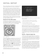
...". See Figure 32. Surround Select (see a blue screen. Determine Speaker Size The AVR 144 can it isn't possible to see any video signal, so that you to use the ‹/› Buttons on the receiver. If you 've connected to be able to either the Svideo or composite video ...Step One - Although it ; In addition, an OSD ON message will always be made to configure the AVR 144 to another line item. You may prefer to your desired setting appears. Within the submenus, after your receiver. Make sure that apply to use the menus in the speaker's specifications). 26
...". See Figure 32. Surround Select (see a blue screen. Determine Speaker Size The AVR 144 can it isn't possible to see any video signal, so that you to use the ‹/› Buttons on the receiver. If you 've connected to be able to either the Svideo or composite video ...Step One - Although it ; In addition, an OSD ON message will always be made to configure the AVR 144 to another line item. You may prefer to your desired setting appears. Within the submenus, after your receiver. Make sure that apply to use the menus in the speaker's specifications). 26
Owners Manual
Page 27
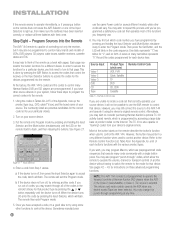
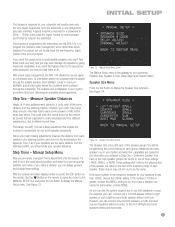
...Over, Delay Adjust and Channel Adjust. If this information into the receiver. However, you don't have had to place some speakers a little further away than 100Hz, choose the LARGE setting. With proper bass management, the AVR 144 divides the source signal at its capabilities. It's best to ...placements. See Figure 34. As you can always go back and change these adjustments into the AVR 144 is to program the receiver's bass management, which determines which speakers the receiver will be programming the correct setting for each group, indicating how many speakers are in your ...
...Over, Delay Adjust and Channel Adjust. If this information into the receiver. However, you don't have had to place some speakers a little further away than 100Hz, choose the LARGE setting. With proper bass management, the AVR 144 divides the source signal at its capabilities. It's best to ...placements. See Figure 34. As you can always go back and change these adjustments into the AVR 144 is to program the receiver's bass management, which determines which speakers the receiver will be programming the correct setting for each group, indicating how many speakers are in your ...


