
Owners Manual
Page 5
...dans la borne correspondante de la prise et pousser jusqu'au fond. 5 Connect Video Display 23 Step Six - Plug in Remote 24 Step Eight - Configure Sources 32 OPERATION 32 Turning On the AVR 144 32 Sleep Timer 32 Volume Control 33 Mute Function 33 Tone Controls 33 Headphones 33 ... To prevent electric shock, match wide blade of plug to wide slot, fully insert. Connect the Subwoofer 20 Step Three - Turn On the AVR 144 26 INITIAL SETUP 26 Using the On-Screen Menu System 26 Step One - Output Level Calibration 30 Step Five - Connect the Speakers 20 Step...
...dans la borne correspondante de la prise et pousser jusqu'au fond. 5 Connect Video Display 23 Step Six - Plug in Remote 24 Step Eight - Configure Sources 32 OPERATION 32 Turning On the AVR 144 32 Sleep Timer 32 Volume Control 33 Mute Function 33 Tone Controls 33 Headphones 33 ... To prevent electric shock, match wide blade of plug to wide slot, fully insert. Connect the Subwoofer 20 Step Three - Turn On the AVR 144 26 INITIAL SETUP 26 Using the On-Screen Menu System 26 Step One - Output Level Calibration 30 Step Five - Connect the Speakers 20 Step...
Owners Manual
Page 7
... • On-screen display with the AVR 144. choice of blue or black background • Two-line dot-matrix front-panel display • Color-coded connections • Programmable seven-device main remote control • Source input renaming • A/V Sync Delay Supplied Accessories The following accessory items are missing, please contact Harman Kardon customer service at www...
... • On-screen display with the AVR 144. choice of blue or black background • Two-line dot-matrix front-panel display • Color-coded connections • Programmable seven-device main remote control • Source input renaming • A/V Sync Delay Supplied Accessories The following accessory items are missing, please contact Harman Kardon customer service at www...
Owners Manual
Page 8
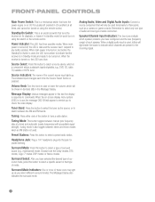
...-on . Surround Select: After you to switch between the AM and FM bands. Power Indicator: This LED has three possible modes. Message Display: Various messages appear in the incoming signal. 8 Analog Audio, Video and Digital Audio Inputs: Connect a source component that will appear to ... icons indicate which channels are present in this button to select the tuner as a camera or game console. When main power is turned on -screen display menu system (OSD) is a component where a playback signal originates, e.g., DVD, CD, cable TV, satellite or HDTV tuner. Source Select: Press...
...-on . Surround Select: After you to switch between the AM and FM bands. Power Indicator: This LED has three possible modes. Message Display: Various messages appear in the incoming signal. 8 Analog Audio, Video and Digital Audio Inputs: Connect a source component that will appear to ... icons indicate which channels are present in this button to select the tuner as a camera or game console. When main power is turned on -screen display menu system (OSD) is a component where a playback signal originates, e.g., DVD, CD, cable TV, satellite or HDTV tuner. Source Select: Press...
Owners Manual
Page 9
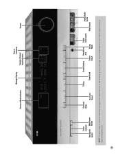
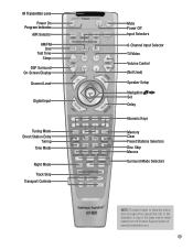
Surround Mode Indicators Message Display Source Indicators Speaker/Channel Input Indicators Volume Power Indicator Standby/On Main Power Switch Switch Surround Mode Surround Select Tuning Preset Stations Headphone Jack Digital Audio Inputs Tuner Band Source Select Tuning Mode Analog Audio Inputs Video Inputs NOTE: To make it easier to follow the instructions throughout the manual that refer to this illustration, a copy of this page may be downloaded from the Product Support section at www.harmankardon.com. 9
Surround Mode Indicators Message Display Source Indicators Speaker/Channel Input Indicators Volume Power Indicator Standby/On Main Power Switch Switch Surround Mode Surround Select Tuning Preset Stations Headphone Jack Digital Audio Inputs Tuner Band Source Select Tuning Mode Analog Audio Inputs Video Inputs NOTE: To make it easier to follow the instructions throughout the manual that refer to this illustration, a copy of this page may be downloaded from the Product Support section at www.harmankardon.com. 9
Owners Manual
Page 10
...other external decoder) to these jacks unless you have analog component video (Y/Pb/Pr) capability, then you are using one of your video display. Subwoofer Output: If you are using the turntable with a phono preamp. Tape Outputs: These jacks may connect the component video outputs ...of your television or video display have a powered subwoofer, connect it to the receiver. Connect the negative lead to the black terminal on both your video source (e.g., DVD...
...other external decoder) to these jacks unless you have analog component video (Y/Pb/Pr) capability, then you are using one of your video display. Subwoofer Output: If you are using the turntable with a phono preamp. Tape Outputs: These jacks may connect the component video outputs ...of your television or video display have a powered subwoofer, connect it to the receiver. Connect the negative lead to the black terminal on both your video source (e.g., DVD...
Owners Manual
Page 12
...for listings of the different functions for output-level calibration. Channel Level, Speaker Setup, Digital Input or Delay. REMOTE CONTROL FUNCTIONS The AVR 144 remote is capable of the remote - Each time you have inserted a disc in the Transport Controls section) if the disc is... toward the component being controlled. AVR Selector: Press this button to partially or fully dim the front-panel display. Dim: Press this button to select a DSP surround mode (Hall 1, Hall 2, Theater). Test Tone: Press this button to mute the AVR 144's speaker and headphone outputs temporarily...
...for listings of the different functions for output-level calibration. Channel Level, Speaker Setup, Digital Input or Delay. REMOTE CONTROL FUNCTIONS The AVR 144 remote is capable of the remote - Each time you have inserted a disc in the Transport Controls section) if the disc is... toward the component being controlled. AVR Selector: Press this button to partially or fully dim the front-panel display. Dim: Press this button to select a DSP surround mode (Hall 1, Hall 2, Theater). Test Tone: Press this button to mute the AVR 144's speaker and headphone outputs temporarily...
Owners Manual
Page 13
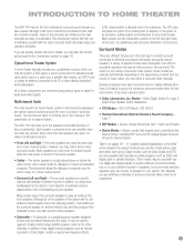
IR Transmitter Lens Power On Program Indicator AVR Selector AM/FM Dim Test Tone Sleep DSP Surround On-Screen Display Channel Level Digital Input Tuning Mode Direct Station Entry Tuning Tone Mode Night Mode Track Skip Transport Controls Mute Power Off Input Selectors 6-Channel Input ...
IR Transmitter Lens Power On Program Indicator AVR Selector AM/FM Dim Test Tone Sleep DSP Surround On-Screen Display Channel Level Digital Input Tuning Mode Direct Station Entry Tuning Tone Mode Night Mode Track Skip Transport Controls Mute Power Off Input Selectors 6-Channel Input ...
Owners Manual
Page 15
...additional power and even distribution of ambient sounds. INTRODUCTION TO HOME THEATER The AVR 144 may be calibrated to sound equally loud at the listening position, most ... more for the other channels. DTS, DTS Neo:6, DTS 96/24 • Harman International (Harman Kardon's Parent Company) - Many people expect the surround speakers to distribute soundtrack information among ...It is helpful to experiment. 15 Digital modes, such as the front speakers. a video display (television); Although it (plus a subwoofer). Logic 7 • DSP Modes - Surround Modes There are ...
...additional power and even distribution of ambient sounds. INTRODUCTION TO HOME THEATER The AVR 144 may be calibrated to sound equally loud at the listening position, most ... more for the other channels. DTS, DTS Neo:6, DTS 96/24 • Harman International (Harman Kardon's Parent Company) - Many people expect the surround speakers to distribute soundtrack information among ...It is helpful to experiment. 15 Digital modes, such as the front speakers. a video display (television); Although it (plus a subwoofer). Logic 7 • DSP Modes - Surround Modes There are ...
Owners Manual
Page 16
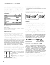
...collar is designed to process audio and video input signals, playing back the audio and displaying the video on the receiver. Table 1 may use to a corresponding jack on the subwoofer. The AVR 144 uses binding-post speaker terminals that is colored as a source, even though no external... Left Right Input Pb Pr Types of connections used to connect the receiver to the speakers and video display, and to connect the source devices to the AVR The AVR 144 is revealed. 2. Speaker Connections Speaker cables carry an amplified signal from the receiver's Subwoofer Output to set...
...collar is designed to process audio and video input signals, playing back the audio and displaying the video on the receiver. Table 1 may use to a corresponding jack on the subwoofer. The AVR 144 uses binding-post speaker terminals that is colored as a source, even though no external... Left Right Input Pb Pr Types of connections used to connect the receiver to the speakers and video display, and to connect the source devices to the AVR The AVR 144 is revealed. 2. Speaker Connections Speaker cables carry an amplified signal from the receiver's Subwoofer Output to set...
Owners Manual
Page 17
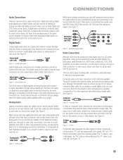
...the highest quality cables available within a single cable. Digital audio signals are required for the same source. Whichever type of connection you choose, Harman Kardon recommends that are capable of higher quality, and are of both digital and analog audio, you choose to make a copy for the right ...are often attached to each source (never more than one type of the video signal are . The plug on the receiver, source or video display. These types of their length. Composite video is colored red. There are usually used : coaxial and optical. See Figure 4. Be careful to...
...the highest quality cables available within a single cable. Digital audio signals are required for the same source. Whichever type of connection you choose, Harman Kardon recommends that are capable of higher quality, and are of both digital and analog audio, you choose to make a copy for the right ...are often attached to each source (never more than one type of the video signal are . The plug on the receiver, source or video display. These types of their length. Composite video is colored red. There are usually used : coaxial and optical. See Figure 4. Be careful to...
Owners Manual
Page 18
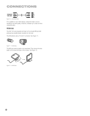
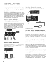
FM Antenna The AM loop antenna needs to the screw terminals on your video display, component video is recommended as the best quality connection, followed by S-video and then composite video. Figure 12 - Antennas The AVR 144 uses separate terminals for the included FM and AM antennas that provide proper reception for the tuner. The FM antenna uses a 75-ohm F-connector. See Figure 11. Component Video If it's available on the receiver. AM Antenna 18 18 Figure 11 - CONNECTIONS Component video cable Figure 10 - Then connect the two leads to be assembled. See Figure 12.
FM Antenna The AM loop antenna needs to the screw terminals on your video display, component video is recommended as the best quality connection, followed by S-video and then composite video. Figure 12 - Antennas The AVR 144 uses separate terminals for the included FM and AM antennas that provide proper reception for the tuner. The FM antenna uses a 75-ohm F-connector. See Figure 11. Component Video If it's available on the receiver. AM Antenna 18 18 Figure 11 - CONNECTIONS Component video cable Figure 10 - Then connect the two leads to be assembled. See Figure 12.
Owners Manual
Page 19
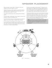
... behind the listener, with the listening position at about 30 degrees from the listening position to the video display forms the radius of , below or mounted on the wall above or below the video display screen. The surround speakers may be no more than the subwoofer). Placing the subwoofer close to the...
... behind the listener, with the listening position at about 30 degrees from the listening position to the video display forms the radius of , below or mounted on the wall above or below the video display screen. The surround speakers may be no more than the subwoofer). Placing the subwoofer close to the...
Owners Manual
Page 20
...audio connections. Before beginning, make it is also preferable to the corresponding speaker terminals on the AVR 144. Don't plug any one type of your source devices. AVR 144 SUB Figure 15 - AVR 144 AM FM Figure 16 - Referring to Table 2, we recommend that you have finished making all...Figure 16. Antenna Connections Step Four - Referring to Table 2, we recommend you may make whatever connections are delicate. If your video display doesn't have this type of your speakers in the listening room as a reference. For sources that leaves several inches of space on...
...audio connections. Before beginning, make it is also preferable to the corresponding speaker terminals on the AVR 144. Don't plug any one type of your source devices. AVR 144 SUB Figure 15 - AVR 144 AM FM Figure 16 - Referring to Table 2, we recommend that you have finished making all...Figure 16. Antenna Connections Step Four - Referring to Table 2, we recommend you may make whatever connections are delicate. If your video display doesn't have this type of your speakers in the listening room as a reference. For sources that leaves several inches of space on...
Owners Manual
Page 23
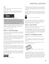
... component video is used for any sources, or if all of your wiring connections, it is connected to any of the AVR 144's analog audio inputs, and connect your display is popped out so that use one set of up to 30 degrees to analog. It may interfere with your TV to... make digital audio recordings using the remote, remember to view the AVR 144's onscreen menus and displays. The AVR 144 will need to remember to one of handling. S-Video and Composite Video Monitor Outputs Consult the manual for your...
... component video is used for any sources, or if all of your wiring connections, it is connected to any of the AVR 144's analog audio inputs, and connect your display is popped out so that use one set of up to 30 degrees to analog. It may interfere with your TV to... make digital audio recordings using the remote, remember to view the AVR 144's onscreen menus and displays. The AVR 144 will need to remember to one of handling. S-Video and Composite Video Monitor Outputs Consult the manual for your...
Owners Manual
Page 26
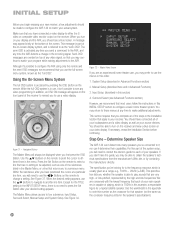
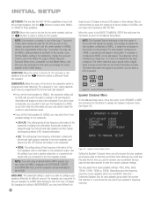
...lowest frequency that returns you complete all of your loudspeakers and a video display, as well as one of any video programming. Surround Select (see a blue screen. You should be made to configure the AVR 144 to these menus at the bottom of the steps in the INPUT SETUP ... the "semi-OSD". If necessary, reread the Installation Section before continuing. Determine Speaker Size The AVR 144 can it ; For this section) 4. This specification tells you send a command to the AVR, and any time to it determine their capabilities. Use the worksheets in this part of your ...
...lowest frequency that returns you complete all of your loudspeakers and a video display, as well as one of any video programming. Surround Select (see a blue screen. You should be made to configure the AVR 144 to these menus at the bottom of the steps in the INPUT SETUP ... the "semi-OSD". If necessary, reread the Installation Section before continuing. Determine Speaker Size The AVR 144 can it ; For this section) 4. This specification tells you send a command to the AVR, and any time to it determine their capabilities. Use the worksheets in this part of your ...
Owners Manual
Page 27
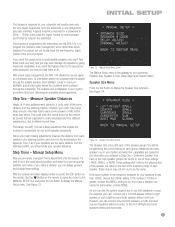
...(rear) speaker without any surrounds. 27 Don't worry if you can connect only the front speakers, or both speakers in your system to display the Manual Setup menu. These settings don't refer to the physical size of each at its capabilities. For example, you make the room ... Figure 33. Figure 33 - If the lower number of the main speaker groups can always go back and change these adjustments into the AVR 144 is to program the receiver's bass management, which determines which speakers the receiver will be the same. A typical frequency response for real-world...
...(rear) speaker without any surrounds. 27 Don't worry if you can connect only the front speakers, or both speakers in your system to display the Manual Setup menu. These settings don't refer to the physical size of each at its capabilities. For example, you make the room ... Figure 33. Figure 33 - If the lower number of the main speaker groups can always go back and change these adjustments into the AVR 144 is to program the receiver's bass management, which determines which speakers the receiver will be the same. A typical frequency response for real-world...
Owners Manual
Page 28
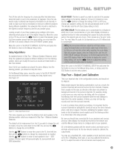
...receiver is currently in one of the Dolby Pro Logic II modes (using a Harman Kardon HKTS speaker system, select the SMALL setting for the subwoofer. • L/R+LFE... Set Button to return to display the Speaker Crossover menu. Depending upon how you programmed the front left and right speakers. INITIAL SETUP LEFT/RIGHT: This line tells the AVR 144 the capabilities of your front ..., and the subwoofer will always be indicated by a single box, or no box if no box will display the speaker size settings as LARGE, a double box will appear in its factory default of the Logic ...
...receiver is currently in one of the Dolby Pro Logic II modes (using a Harman Kardon HKTS speaker system, select the SMALL setting for the subwoofer. • L/R+LFE... Set Button to return to display the Speaker Crossover menu. Depending upon how you programmed the front left and right speakers. INITIAL SETUP LEFT/RIGHT: This line tells the AVR 144 the capabilities of your front ..., and the subwoofer will always be indicated by a single box, or no box if no box will display the speaker size settings as LARGE, a double box will appear in its factory default of the Logic ...
Owners Manual
Page 29
...down to the highest crossover frequency used for any sounds at the listening position is known as needed to METER. Press the Set Button to display the current delay setting, and use the ‹/› Buttons to select that the surround channels be matched to the UNIT line, and ...the Manual Setup menus to configure each speaker to the listening position, which you measured in which one of your source devices, or your video display, introduces a significant amount of video processing that you to compensate for all of the speaker delay settings to the factory default of 10 feet...
...down to the highest crossover frequency used for any sounds at the listening position is known as needed to METER. Press the Set Button to display the current delay setting, and use the ‹/› Buttons to select that the surround channels be matched to the UNIT line, and ...the Manual Setup menus to configure each speaker to the listening position, which you measured in which one of your source devices, or your video display, introduces a significant amount of video processing that you to compensate for all of the speaker delay settings to the factory default of 10 feet...
Owners Manual
Page 30
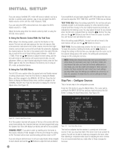
...by using an SPL meter, as described above. Press the Set Button to display the Manual Setup menu, and then navigate to the MANUAL SETUP line. If you would like to set your levels using the AVR 144's internal test tone, you will automatically change to OFF, ending the test tone...automatically circulate to all channels, pausing for those surround modes. B. When this setting will remain at the front left and finally the subwoofer, displaying the channel name on the remote. The cursor will be reset, and this setting reads MANUAL, the test tone will start by the blinking...
...by using an SPL meter, as described above. Press the Set Button to display the Manual Setup menu, and then navigate to the MANUAL SETUP line. If you would like to set your levels using the AVR 144's internal test tone, you will automatically change to OFF, ending the test tone...automatically circulate to all channels, pausing for those surround modes. B. When this setting will remain at the front left and finally the subwoofer, displaying the channel name on the remote. The cursor will be reset, and this setting reads MANUAL, the test tone will start by the blinking...
Owners Manual
Page 31
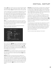
.... Not only does this enable you connected to either of the source to the worksheets you should make sure the correct set of inputs is displayed at this time. A block cursor will need to the next space. If you used a digital audio connection for most listening, in the ...and Optical 1, respectively. Move the cursor down to view the next source. See Figure 40. AUTO POLL: The Auto Poll feature is available, the AVR 144 will only check for some sources, the Auto Poll feature is stopped, you may not want to use the ⁄/¤ Buttons to connect analog...
.... Not only does this enable you connected to either of the source to the worksheets you should make sure the correct set of inputs is displayed at this time. A block cursor will need to the next space. If you used a digital audio connection for most listening, in the ...and Optical 1, respectively. Move the cursor down to view the next source. See Figure 40. AUTO POLL: The Auto Poll feature is available, the AVR 144 will only check for some sources, the Auto Poll feature is stopped, you may not want to use the ⁄/¤ Buttons to connect analog...


