User Manual
Page 1
... adjacent to change without notice. AUTOMOBILE, SPACE HEATER, WATER HEATER,ETC.) INSURE THAT THE ENCLOSED AREA IS PROPERLY VENTILATED. IN THE ABSENCE OF LOCAL CODES REFER TO : NATIONAL ELECTRICAL CODE NFPA 70 NFPA 90A & 90B UNIFORM MECHANICAL CODE READ THESE INSTRUCTIONS COMPLETELY BEFORE ATTEMPTING TO INSTALL OR SERVICE THIS APPLIANCE. IF IN DOUBT CONTACT YOUR LOCAL AUTHORITIES. No. 0010578632A Installation & Operation Manual Air Handler 13...
... adjacent to change without notice. AUTOMOBILE, SPACE HEATER, WATER HEATER,ETC.) INSURE THAT THE ENCLOSED AREA IS PROPERLY VENTILATED. IN THE ABSENCE OF LOCAL CODES REFER TO : NATIONAL ELECTRICAL CODE NFPA 70 NFPA 90A & 90B UNIFORM MECHANICAL CODE READ THESE INSTRUCTIONS COMPLETELY BEFORE ATTEMPTING TO INSTALL OR SERVICE THIS APPLIANCE. IF IN DOUBT CONTACT YOUR LOCAL AUTHORITIES. No. 0010578632A Installation & Operation Manual Air Handler 13...

User Manual
Page 2
... questions arise contact the local EPA office. INDEX TOPIC Index Physical dimensions Replacement Parts Source Installation Requirements Air Flow Orientation Horizontal Left-Hand Instructions Refrigerant Tubing Condensate Removal Electrical Connections Thermostat Wiring Orifice Change Circulating Air Duct Blower Performance Start-up Regular Maintenance Model Number Explanation PAGE 2 3 6 6 7 8 9 10 10 11 13 13 14 15 15 16 The United States Environmental Protection Agency (EPA) has issued various regulations regarding the...
... questions arise contact the local EPA office. INDEX TOPIC Index Physical dimensions Replacement Parts Source Installation Requirements Air Flow Orientation Horizontal Left-Hand Instructions Refrigerant Tubing Condensate Removal Electrical Connections Thermostat Wiring Orifice Change Circulating Air Duct Blower Performance Start-up Regular Maintenance Model Number Explanation PAGE 2 3 6 6 7 8 9 10 10 11 13 13 14 15 15 16 The United States Environmental Protection Agency (EPA) has issued various regulations regarding the...
User Manual
Page 4
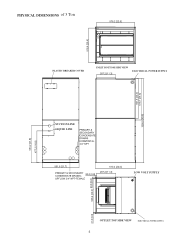
PHYSICAL DIMENSIONS of 3 Ton PLASTIC BREAKER COVER INLET BOTTOM SIDE VIEW ELECTRICAL POWER SUPPLY SUCTION LINE LIQUID LINE LOW VOLT SUPPLY OUTLET TOP SIDE VIEW ELECTRICAL POWER SUPPLY 4
PHYSICAL DIMENSIONS of 3 Ton PLASTIC BREAKER COVER INLET BOTTOM SIDE VIEW ELECTRICAL POWER SUPPLY SUCTION LINE LIQUID LINE LOW VOLT SUPPLY OUTLET TOP SIDE VIEW ELECTRICAL POWER SUPPLY 4
User Manual
Page 5
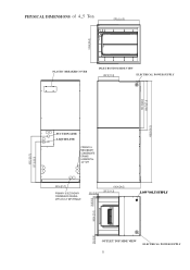
PHYSICAL DIMENSIONS of 4,5 Ton PLASTIC BREAKER COVER INLET BOTTOM SIDE VIEW ELECTRICAL POWER SUPPLY SUCTION LINE LIQUID LINE LOW VOLT SUPPLY OUTLET TOP SIDE VIEW 5 ELECTRICAL POWER SUPPLY
PHYSICAL DIMENSIONS of 4,5 Ton PLASTIC BREAKER COVER INLET BOTTOM SIDE VIEW ELECTRICAL POWER SUPPLY SUCTION LINE LIQUID LINE LOW VOLT SUPPLY OUTLET TOP SIDE VIEW 5 ELECTRICAL POWER SUPPLY
User Manual
Page 6
... unit can be installed in the vertical or right horizontal position without removing permanent structure. When installed on the rating plate. REPLACEMENT PARTS SOURCE Replacement parts are available through local distributors.When ordering replacement parts, give the COMPLETE model and serial numbers shown on a base, the base must be installed with a separate drain line properly sloped and terminated in an area visible to the owner. INSTALLATION REQUIREMENTS Before installing...
... unit can be installed in the vertical or right horizontal position without removing permanent structure. When installed on the rating plate. REPLACEMENT PARTS SOURCE Replacement parts are available through local distributors.When ordering replacement parts, give the COMPLETE model and serial numbers shown on a base, the base must be installed with a separate drain line properly sloped and terminated in an area visible to the owner. INSTALLATION REQUIREMENTS Before installing...
User Manual
Page 7
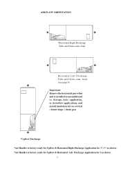
front Horizontal Left Discharge Tube and Drain conn. front (see page 6) Important: Remove the horizontal pan when unit is installed in unconditioned i.e. (Garage, Attic ) application, or downflow applications, and install insulation kit on vertical ( donut shape ) drain pan. *Upflow Discharge *Air Handler is factory ready for Upflow & Horizontal Right Discharge Application for 3*4*5 as shown. *Air Handler is factory ready for Upflow & Horizontal Left Discharge Application for 2 as shown. 7 AIR FLOW ORIENTATION *Horizontal Right Discharge Tube and Drain conn.
front Horizontal Left Discharge Tube and Drain conn. front (see page 6) Important: Remove the horizontal pan when unit is installed in unconditioned i.e. (Garage, Attic ) application, or downflow applications, and install insulation kit on vertical ( donut shape ) drain pan. *Upflow Discharge *Air Handler is factory ready for Upflow & Horizontal Right Discharge Application for 3*4*5 as shown. *Air Handler is factory ready for Upflow & Horizontal Left Discharge Application for 2 as shown. 7 AIR FLOW ORIENTATION *Horizontal Right Discharge Tube and Drain conn.

User Manual
Page 8
... used. 8) In all cooling applications, a secondary drain pan must be installed on the primary drain and on the lower access panel. 10) Failure to the user. 9) WARNING: The "A" coil contains 150 p.s.i. Traps must be leveled and then pitched 1/4" toward drain side. Note: Push the assembly completely to over torque screws. Snap in the drain cover on horizontal drain pan. of the cavity. 6) Replace...
... used. 8) In all cooling applications, a secondary drain pan must be installed on the primary drain and on the lower access panel. 10) Failure to the user. 9) WARNING: The "A" coil contains 150 p.s.i. Traps must be leveled and then pitched 1/4" toward drain side. Note: Push the assembly completely to over torque screws. Snap in the drain cover on horizontal drain pan. of the cavity. 6) Replace...
User Manual
Page 9
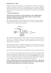
... a lubricant. Therefore a removal pump or float switch must be used not to the plastic drain pan during the soldering process. NOTE: AFTER INSTALLATION AND POSITIONING THE UNIT , THE DRAIN PAN BEING USED SHOULD BE TESTED BY FILLING IT WITH WATER TO ENSURE PROPER DRAINAGE AND CHECK FOR LEAKS. 9 The total workable height of this precaution will dissolve Styrofoam and certain types of these...
... a lubricant. Therefore a removal pump or float switch must be used not to the plastic drain pan during the soldering process. NOTE: AFTER INSTALLATION AND POSITIONING THE UNIT , THE DRAIN PAN BEING USED SHOULD BE TESTED BY FILLING IT WITH WATER TO ENSURE PROPER DRAINAGE AND CHECK FOR LEAKS. 9 The total workable height of this precaution will dissolve Styrofoam and certain types of these...
User Manual
Page 10
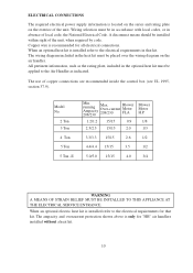
... code, the National Electrical Code. The wiring diagram included in absence of the unit. The use of the unit, when required by code. When an optional heat kit is recommended for that kit. Copper wire is installed refer to the Air Handler as indicated. A disconnect means should be applied to the electrical requirements in the optional heat kit must be installed within sight of copper connections are recommended inside the control...
... code, the National Electrical Code. The wiring diagram included in absence of the unit. The use of the unit, when required by code. When an optional heat kit is recommended for that kit. Copper wire is installed refer to the Air Handler as indicated. A disconnect means should be applied to the electrical requirements in the optional heat kit must be installed within sight of copper connections are recommended inside the control...

User Manual
Page 11
... can adopt different power switch show diagram 2. Note: Thermostat C : COM. R : AC24V THERMOSTAT Y : COMPRESSOR G O Y R C G : FAN O : 4 -WAY VALVE TO INDOOR For detailed Thermostat, please connect FAN RELAY CONTROL corresponding terminal according to above control specification. This mode is RUN SWITCH MODE SWITCH Open for heating Close for cooling control the indoor unit & heat pump outdoor unit at the same time no air supply mode. If need select the air supply mode, switch can adopt multi-connect switch or select switch. HEAT HEAT PUMP COOLING TO FAN RELAY CONTROL YL RD...
... can adopt different power switch show diagram 2. Note: Thermostat C : COM. R : AC24V THERMOSTAT Y : COMPRESSOR G O Y R C G : FAN O : 4 -WAY VALVE TO INDOOR For detailed Thermostat, please connect FAN RELAY CONTROL corresponding terminal according to above control specification. This mode is RUN SWITCH MODE SWITCH Open for heating Close for cooling control the indoor unit & heat pump outdoor unit at the same time no air supply mode. If need select the air supply mode, switch can adopt multi-connect switch or select switch. HEAT HEAT PUMP COOLING TO FAN RELAY CONTROL YL RD...

User Manual
Page 12
... different power switch show diagram 5. This mode is control the indoor unit & cooling only outdoor unit at the same time no air supply mode. Note: Thermostat C: COM. TO FAN RELAY CONTROL RD BL CY RD BL 24V COM For Thermostat only control Air TO OUTDOOR UNIT C,Y TRANSFORMER Conditioning open /stop , hot Diagram 4 control Environment temperature, SWITCH can be mechanical type or programmable type. R : AC24V TERMOSTAT Y : COMPRESSOR G Y R C G : FAN For detailed Thermostat, please connect corresponding terminal according to above control specification. The...
... different power switch show diagram 5. This mode is control the indoor unit & cooling only outdoor unit at the same time no air supply mode. Note: Thermostat C: COM. TO FAN RELAY CONTROL RD BL CY RD BL 24V COM For Thermostat only control Air TO OUTDOOR UNIT C,Y TRANSFORMER Conditioning open /stop , hot Diagram 4 control Environment temperature, SWITCH can be mechanical type or programmable type. R : AC24V TERMOSTAT Y : COMPRESSOR G Y R C G : FAN For detailed Thermostat, please connect corresponding terminal according to above control specification. The...

User Manual
Page 13
... kit table 1 in manual. 4) Use a torch to remove the spin closure on the suction line . 5) Use a torch to minimize the possibility of noise transmission. The use of flexible duct connectors is greater in this unit match the comparable capacity of the ducts to prevent condensation. THE CAPACITY OF THE OUTDOOR UNIT SHOULD NEVER EXCEED THE CAPACITY OF THE INDOOR UNIT. or tighten 1/6 turn. 10) Replace...
... kit table 1 in manual. 4) Use a torch to remove the spin closure on the suction line . 5) Use a torch to minimize the possibility of noise transmission. The use of flexible duct connectors is greater in this unit match the comparable capacity of the ducts to prevent condensation. THE CAPACITY OF THE OUTDOOR UNIT SHOULD NEVER EXCEED THE CAPACITY OF THE INDOOR UNIT. or tighten 1/6 turn. 10) Replace...
User Manual
Page 14
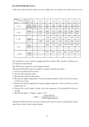
... terminal block/circuit breaker. 7) The BTUH output = (Voltage x Amps x 3.41) output (BTUH) CFM = 1.08 X temperature rise Should the CFM need to obtain an average. 5) Subtract the return temperature from the supply temperature. This is referred to as shown on the wiring diagram. 14 The CFM can be in place. 2) Start the unit in the heat mode. 3) Measure the return air temperature. 4) Measure the supply temperature. Model Static...
... terminal block/circuit breaker. 7) The BTUH output = (Voltage x Amps x 3.41) output (BTUH) CFM = 1.08 X temperature rise Should the CFM need to obtain an average. 5) Subtract the return temperature from the supply temperature. This is referred to as shown on the wiring diagram. 14 The CFM can be in place. 2) Start the unit in the heat mode. 3) Measure the return air temperature. 4) Measure the supply temperature. Model Static...

User Manual
Page 15
... serious personal injury or death. Low voltage wiring is installed, when necessary, and pitched to insure that the circulating air filter(s) is elevated when installed in place and secured. Drain pans and drain tubing were leak checked with water. Unit is cleaned or replaced. REGULAR MAINTENANCE WARNING DISCONNECT ALL POWER SUPPLIES BEFORE PERFORMING ANY SERVICE. Unit is recommended that all electrical connections are sealed. It is protected...
... serious personal injury or death. Low voltage wiring is installed, when necessary, and pitched to insure that the circulating air filter(s) is elevated when installed in place and secured. Drain pans and drain tubing were leak checked with water. Unit is cleaned or replaced. REGULAR MAINTENANCE WARNING DISCONNECT ALL POWER SUPPLIES BEFORE PERFORMING ANY SERVICE. Unit is recommended that all electrical connections are sealed. It is protected...


