Haier HB6000VD1M22-E Support and Manuals
Get Help and Manuals for this Haier item
View All Support Options Below
Free Haier HB6000VD1M22-E manuals!
Problems with Haier HB6000VD1M22-E?
Ask a Question
Free Haier HB6000VD1M22-E manuals!
Problems with Haier HB6000VD1M22-E?
Ask a Question
Popular Haier HB6000VD1M22-E Manual Pages
User Manual - Page 1
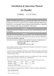
... change without notice. AUTOMOBILE, SPACE HEATER, WATER HEATER,ETC.) INSURE THAT THE ENCLOSED AREA IS PROPERLY VENTILATED. IN THE ABSENCE OF LOCAL CODES REFER TO : NATIONAL ELECTRICAL CODE NFPA 70 NFPA 90A & 90B UNIFORM MECHANICAL CODE
READ THESE INSTRUCTIONS COMPLETELY BEFORE ATTEMPTING TO INSTALL OR SERVICE THIS APPLIANCE. SOME LOCALITIES MAY REQUIRE THE INSTALLER/SERVICER TO BE LICENSED.
User Manual - Page 2
.... This appliance is approved for connection to air distribution ductwork.
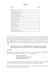
2 INDEX
TOPIC
General Physical dimensions Replacement Parts Source Installation Requirements Air Flow Orientation Horizontal Left-Hand Instructions Refrigerant Tubing Condensate Removal Electrical Connections Thermostat Wiring Orifice Change Circulating Air Duct Blower Performance Start-up Regular Maintenance Model Number...
User Manual - Page 4

PHYSICAL DIMENSIONS of 3 Ton
PLASTIC BREAKER COVER
INLET BOTTOM SIDE VIEW ELECTRICAL POWER SUPPLY
SUCTION LINE LIQUID LINE
LOW VOLT SUPPLY
ELECTRICAL POWER SUPPLY
4
User Manual - Page 5

PHYSICAL DIMENSIONS of 4,5 Ton
PLASTIC BREAKER COVER
INLET BOTTOM SIDE VIEW ELECTRICAL POWER SUPPLY
SUCTION LINE LIQUID LINE
LOW VOLT SUPPLY
ELECTRICAL POWER SUPPLY
5
User Manual - Page 6
..., must also be provided by similar means. Appliances installed in garages, ware houses or other areas where they may be subjected to mechanical damage must be suitably guarded against such damage by that it is properly sized and adequate power is designed for service or replacement must be considered without modification. This product is...
User Manual - Page 7
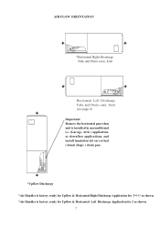
front (see page 6) Important: Remove the horizontal pan when unit is installed in unconditioned i.e. (Garage, Attic ) application, or downflow applications, and install insulation kit on vertical ( donut shape ) drain pan.
*Upflow Discharge *Air Handler is factory ready for Upflow & Horizontal Right Discharge Application for 3*4*5 as shown. *Air ...
User Manual - Page 8

...setting up flowrator assembly for proper drainage by the installer and placed under the entire unit with the horizontal drain pan on the left horizontal position as shown in Fig.2. HORIZONTAL LEFT-HAND INSTRUCTIONS
Important: Read instructions...cavity.
6) Replace the J-shape metal bracket or brackets on the vertical drain pan and place the plastic oval gasket on the right lower service panel.
...
User Manual - Page 9
...should a blocked drain occur.
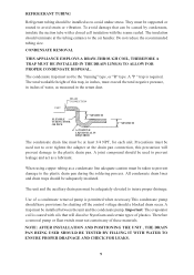
Therefore a removal pump or float switch must be supported or routed to insure proper drainage. They must not contain any of a condensate...must be adequately elevated to avoid strain or vibration. CONDENSATE REMOVAL
THIS APPLIANCE EMPLOYS A DRAW-THROUGH COIL, THEREFORE A TRAP MUST BE INSTALLED IN THE DRAIN LINE(S) TO ALLOW FOR PROPER CONDENSATE DISPOSAL. A ...
User Manual - Page 10
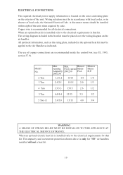
... kit is installed refer to the electrical requirements in that kit. Model No.
2 Ton 3 Ton 4 Ton 5 Ton
5 Ton -E
Min. When an optional electric heat kit is installed refer to the Air Handler as the rating plate, included in absence of copper connections are recommended inside the control box (see UL 1995, section 37.9). The use of local code, the National Electrical Code. Copper...
User Manual - Page 11
...YL
RD
BL
BL
OY C R
TO OUTDOOR UNIT R,C,Y,O
24V
COM
TRANSFORMER
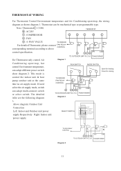
Diagram 3
11 R : AC24V
TERMOSTAT
Y : COMPRESSOR
G
O
Y
R
C
G : FAN
O : 4 -WAY VALUE
TO INDOOR
For detailed Thermostat, please connect FAN RELAY
CONTROL
corresponding terminal according to above
control specification.
This mode is
RUN SWITCH
MODE SWITCH
Open for heating Close for cooling
control the indoor...
User Manual - Page 12

... Respectively Right: Indoor unit power supply.
1 2
SELECT SWITCH 3 4 5 6
TO FAN RELAY CONTROL
RD BL
RD
BL
CY
24V
COM
TO OUTDOOR UNIT C,Y TRANSFORMER
Diagram 6
12
... AC24V
TERMOSTAT
Y : COMPRESSOR
G
Y
R
C
G : FAN
For detailed Thermostat, please connect corresponding terminal according to above control specification.
If need select the air supply mode, switch can adopt ...
User Manual - Page 13
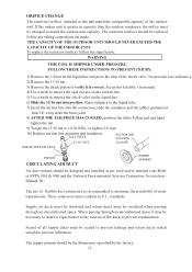
...10) Replace suction line grommet and insulation.
If the indoor unit is correct. The supply plenum should be designed and installed as per local and/or national code.Refer ...Manual "K". Braze tailpiece to the liquid tube.
7) Insert the suction line into position. THE CAPACITY OF THE OUTDOOR UNIT SHOULD NEVER EXCEED THE CAPACITY OF THE INDOOR UNIT. standards. FOLLOW THESE INSTRUCTIONS...
User Manual - Page 14

... heat mode. 3) Measure the return air temperature. 4) Measure the supply temperature.
This can be done in installations. This is referred to obtain an average. 5) Subtract the return temperature from the supply temperature. Model
Static Pressure
0.1
CFM
0.15 0.2
2 Ton
High 900 877 856 Middle 630 614 599
0.25 0.3 0.35 0.4 0.5
835 816 795 766 737...
User Manual - Page 15

... Unit is elevated when installed in place and secured.
A certified service technician should perform other physical damage. Low voltage wiring is connected. Auxiliary drain is installed, when necessary, and...air filter(s) is cleaned or replaced. Retrun and supply ducts are properly sized and tightened. START-UP Prior to insure that all electrical connections are sealed. Tubing should...
Haier HB6000VD1M22-E Reviews
We have not received any reviews for Haier yet.