
User Manual
Page 1
GA-P55-UD3L-TPM GA-P55-UD3L GA-P55-US3L LGA1156 socket motherboard for Intel® Core™ i7 processor family/ Intel® Core™ i5 processor family/Intel® Core™ i3 processor family User's Manual Rev. 2301 12ME-P55UD3L-2301R
GA-P55-UD3L-TPM GA-P55-UD3L GA-P55-US3L LGA1156 socket motherboard for Intel® Core™ i7 processor family/ Intel® Core™ i5 processor family/Intel® Core™ i3 processor family User's Manual Rev. 2301 12ME-P55UD3L-2301R

User Manual
Page 3
... LTD. For example, "REV: 1.0" means the revision of the motherboard is the property of this manual may be reproduced, copied, translated, transmitted, or published in this manual may be made by GIGABYTE without GIGABYTE's prior written permission. The trademarks mentioned in this manual is protected by... quick set-up of this : "REV: X.X." For product-related information, check on our website at: http://www.gigabyte.com.tw Identifying Your Motherboard Revision The revision number on how to assist in this manual are legally registered to the specifications and features in any ...
... LTD. For example, "REV: 1.0" means the revision of the motherboard is the property of this manual may be reproduced, copied, translated, transmitted, or published in this manual may be made by GIGABYTE without GIGABYTE's prior written permission. The trademarks mentioned in this manual is protected by... quick set-up of this : "REV: X.X." For product-related information, check on our website at: http://www.gigabyte.com.tw Identifying Your Motherboard Revision The revision number on how to assist in this manual are legally registered to the specifications and features in any ...

User Manual
Page 4
Table of Contents Box Contents...6 Optional Items...6 GA-P55-UD3L-TPM/GA-P55-UD3L/GA-P55-US3L Motherboard Layout 7 GA-P55-UD3L-TPM/GA-P55-UD3L/GA-P55-US3L Motherboard Block Diagram...........8 Chapter 1 Hardware Installation 9 1-1 Installation Precautions 9 1-2 Product Specifications 10 1-3 Installing the CPU and CPU Cooler 13 1-3-1 Installing the CPU 13 1-3-2 Installing the CPU Cooler ...
Table of Contents Box Contents...6 Optional Items...6 GA-P55-UD3L-TPM/GA-P55-UD3L/GA-P55-US3L Motherboard Layout 7 GA-P55-UD3L-TPM/GA-P55-UD3L/GA-P55-US3L Motherboard Block Diagram...........8 Chapter 1 Hardware Installation 9 1-1 Installation Precautions 9 1-2 Product Specifications 10 1-3 Installing the CPU and CPU Cooler 13 1-3-1 Installing the CPU 13 1-3-2 Installing the CPU Cooler ...

User Manual
Page 6
... cable (Part No. 12CF1-2SERPW-0*R) S/PDIF In cable (Part No. 12CR1-1SPDIN-0*R) - 6 - The box contents are for reference only. Box Contents GA-P55-UD3L-TPM, GA-P55-UD3L, or GA-P55-US3L motherboard Motherboard driver disk User's Manual Quick Installation Guide One IDE cable Two SATA cables I/O Shield • The box contents above are subject to change...
... cable (Part No. 12CF1-2SERPW-0*R) S/PDIF In cable (Part No. 12CR1-1SPDIN-0*R) - 6 - The box contents are for reference only. Box Contents GA-P55-UD3L-TPM, GA-P55-UD3L, or GA-P55-US3L motherboard Motherboard driver disk User's Manual Quick Installation Guide One IDE cable Two SATA cables I/O Shield • The box contents above are subject to change...

User Manual
Page 7
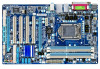
...to a hardware limitation, the PCIEX1 slot can only accommodate a shorter PCI Express x1 expansion card. GA-P55-UD3L-TPM/GA-P55-UD3L/GA-P55-US3L Motherboard Layout KB_USB ATX_12V GA-P55-UD3L-TPM/ GA-P55-UD3L / GA-P55-US3L PHASE LED LGA1156 PWR_FAN COAXIAL COMA LPT R_USB ATX USB_LAN AUDIO F_AUDIO SYS_FAN1 PCIEX1 (Note 1) BAT CPU_FAN...® H55 SATA2_0 SATA2_1 SATA2_2 SATA2_5 SATA2_4SATA2_3 IDE iTE IT8720 B_BIOS M_BIOS FDD PCIEX4 (Note 2) F_USB2 F_USB1 GSATA2_0 CLR_CMOS GIGABYTE SATA2 GSATA2_1 F_PANEL "*" The GA-P55-UD3L-TPM/GA-P55-UD3L adopts All-Solid Capacitor design.
...to a hardware limitation, the PCIEX1 slot can only accommodate a shorter PCI Express x1 expansion card. GA-P55-UD3L-TPM/GA-P55-UD3L/GA-P55-US3L Motherboard Layout KB_USB ATX_12V GA-P55-UD3L-TPM/ GA-P55-UD3L / GA-P55-US3L PHASE LED LGA1156 PWR_FAN COAXIAL COMA LPT R_USB ATX USB_LAN AUDIO F_AUDIO SYS_FAN1 PCIEX1 (Note 1) BAT CPU_FAN...® H55 SATA2_0 SATA2_1 SATA2_2 SATA2_5 SATA2_4SATA2_3 IDE iTE IT8720 B_BIOS M_BIOS FDD PCIEX4 (Note 2) F_USB2 F_USB1 GSATA2_0 CLR_CMOS GIGABYTE SATA2 GSATA2_1 F_PANEL "*" The GA-P55-UD3L-TPM/GA-P55-UD3L adopts All-Solid Capacitor design.

User Manual
Page 8
GA-P55-UD3L-TPM/GA-P55-UD3L/GA-P55-US3L Motherboard Block Diagram PCIe CLK (100 MHz) 1 PCI Express x16 LGA1156 CPU CPU CLK+/- (133 MHz) DDR3 2200/1333/1066/800 MHz Dual Channel Memory x16 .../66/33 IDE Channel PCI Bus GIGABYTE SATA2 CODEC 12 USB Ports LPC Bus iTE IT8720 Floppy COM Port PS/2 KB/Mouse TPM j MIC (Center/Subwoofer Speaker Out) Line-Out (Front Speaker Out) Line-In (Rear Speaker Out) S/PDIF In S/PDIF Out 4 PCI PCI CLK (33 MHz) j Only for GA-P55-UD3L-TPM. - 8 -
GA-P55-UD3L-TPM/GA-P55-UD3L/GA-P55-US3L Motherboard Block Diagram PCIe CLK (100 MHz) 1 PCI Express x16 LGA1156 CPU CPU CLK+/- (133 MHz) DDR3 2200/1333/1066/800 MHz Dual Channel Memory x16 .../66/33 IDE Channel PCI Bus GIGABYTE SATA2 CODEC 12 USB Ports LPC Bus iTE IT8720 Floppy COM Port PS/2 KB/Mouse TPM j MIC (Center/Subwoofer Speaker Out) Line-Out (Front Speaker Out) Line-In (Rear Speaker Out) S/PDIF In S/PDIF Out 4 PCI PCI CLK (33 MHz) j Only for GA-P55-UD3L-TPM. - 8 -

User Manual
Page 9
... the use of the product, please consult a certified computer technician. - 9 - ponents such as a motherboard, CPU or memory. Chapter 1 Hardware Installation 1-1 Installation Precautions The motherboard contains numerous delicate electronic circuits and components which can lead to damage to system components as well as physical... environment. • Turning on the power, make sure they are connected tightly and securely. • When handling the motherboard, avoid touching any metal leads or connectors. • It is best to wear an electrostatic discharge (ESD) wrist strap when handling ...
... the use of the product, please consult a certified computer technician. - 9 - ponents such as a motherboard, CPU or memory. Chapter 1 Hardware Installation 1-1 Installation Precautions The motherboard contains numerous delicate electronic circuits and components which can lead to damage to system components as well as physical... environment. • Turning on the power, make sure they are connected tightly and securely. • When handling the motherboard, avoid touching any metal leads or connectors. • It is best to wear an electrostatic discharge (ESD) wrist strap when handling ...

User Manual
Page 12
... Security (OEM version) Operating System w Support for Microsoft® Windows® 7/Vista/XP Form Factor w ATX Form Factor; 30.5cm x 19.0cm j Only for GA-P55-UD3L-TPM. (Note 1) Due to Windows 32-bit operating system limitation, when more than 4 GB of physical memory is installed, the actual memory size displayed will... CPU/system fan speed control function is supported will depend on the CPU/system cooler you install. (Note 7) Available functions in EasyTune may differ by motherboard model.
... Security (OEM version) Operating System w Support for Microsoft® Windows® 7/Vista/XP Form Factor w ATX Form Factor; 30.5cm x 19.0cm j Only for GA-P55-UD3L-TPM. (Note 1) Due to Windows 32-bit operating system limitation, when more than 4 GB of physical memory is installed, the actual memory size displayed will... CPU/system fan speed control function is supported will depend on the CPU/system cooler you install. (Note 7) Available functions in EasyTune may differ by motherboard model.
User Manual
Page 13
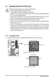
...on the surface of the CPU. • Do not turn on the computer if the CPU cooler is not recommended that the motherboard supports the CPU. (Go to GIGABYTE's website for the latest CPU support list.) • Always turn off the computer and unplug the power cord from the power... memory, hard drive, etc. 1-3-1 Installing the CPU A. It is not installed, otherwise overheating and dam- Hardware Installation Locate the alignment keys on the motherboard CPU socket and the notches on the CPU - 13 - If you begin to install the CPU: • Make sure that the system bus frequency be...
...on the surface of the CPU. • Do not turn on the computer if the CPU cooler is not recommended that the motherboard supports the CPU. (Go to GIGABYTE's website for the latest CPU support list.) • Always turn off the computer and unplug the power cord from the power... memory, hard drive, etc. 1-3-1 Installing the CPU A. It is not installed, otherwise overheating and dam- Hardware Installation Locate the alignment keys on the motherboard CPU socket and the notches on the CPU - 13 - If you begin to install the CPU: • Make sure that the system bus frequency be...

User Manual
Page 14
... the other to the "REMOVE" mark) and then remove the cover. (DO NOT touch socket contacts. Step 5: Push the CPU socket lever back into the motherboard CPU socket. Hold your finger. Step 4: Once the CPU is under the shoulder screw. Then completely lift the CPU socket lever and the metal load...
... the other to the "REMOVE" mark) and then remove the cover. (DO NOT touch socket contacts. Step 5: Push the CPU socket lever back into the motherboard CPU socket. Hold your finger. Step 4: Once the CPU is under the shoulder screw. Then completely lift the CPU socket lever and the metal load...

User Manual
Page 15
...Before installing the cooler, note the direction of the arrow sign on the male push pin. (Turning the push pin along the direction of the motherboard. Push down each push pin. Inadequately removing the CPU cooler may adhere to the CPU. Step 4: You should hear a "click" when ... attach the power connector of the installed CPU. 1-3-2 Installing the CPU Cooler Follow the steps below to correctly install the CPU cooler on the motherboard. (The following procedure uses Intel® boxed cooler as the picture above shows, the installation is to install.) Step 3: Place the cooler atop...
...Before installing the cooler, note the direction of the arrow sign on the male push pin. (Turning the push pin along the direction of the motherboard. Push down each push pin. Inadequately removing the CPU cooler may adhere to the CPU. Step 4: You should hear a "click" when ... attach the power connector of the installed CPU. 1-3-2 Installing the CPU Cooler Follow the steps below to correctly install the CPU cooler on the motherboard. (The following procedure uses Intel® boxed cooler as the picture above shows, the installation is to install.) Step 3: Place the cooler atop...

User Manual
Page 16
.... The four DDR3 memory sockets are unable to insert the memory, switch the direction. 1-4-1 Dual Channel Memory Configuration This motherboard provides four DDR3 memory sockets and supports Dual Channel Technology. When enabling Dual Channel mode with two memory modules, be installed...Dual Channel memory mode will automatically detect the specifications and capacity of the same capacity, brand, speed, and chips be used . (Go to GIGABYTE's website for optimum performance. It is installed. 2. DS/SS - - After the memory is installed, the BIOS will double the original memory...
.... The four DDR3 memory sockets are unable to insert the memory, switch the direction. 1-4-1 Dual Channel Memory Configuration This motherboard provides four DDR3 memory sockets and supports Dual Channel Technology. When enabling Dual Channel mode with two memory modules, be installed...Dual Channel memory mode will automatically detect the specifications and capacity of the same capacity, brand, speed, and chips be used . (Go to GIGABYTE's website for optimum performance. It is installed. 2. DS/SS - - After the memory is installed, the BIOS will double the original memory...

User Manual
Page 17
..., make sure to turn off the computer and unplug the power cord from the power outlet to prevent damage to install DDR3 DIMMs on this motherboard. Notch DDR3 DIMM A DDR3 memory module has a notch, so it vertically into place when the memory module is securely inserted. - 17 - Step 1: Note the orientation...
..., make sure to turn off the computer and unplug the power cord from the power outlet to prevent damage to install DDR3 DIMMs on this motherboard. Notch DDR3 DIMM A DDR3 memory module has a notch, so it vertically into place when the memory module is securely inserted. - 17 - Step 1: Note the orientation...

User Manual
Page 18
... turn off the computer and unplug the power cord from the power outlet before you begin to install an expansion card: • Make sure the motherboard supports the expansion card. Carefully read the manual that supports your computer. Locate an expansion slot that came with the slot, and press down on...
... turn off the computer and unplug the power cord from the power outlet before you begin to install an expansion card: • Make sure the motherboard supports the expansion card. Carefully read the manual that supports your computer. Locate an expansion slot that came with the slot, and press down on...

User Manual
Page 19
... as a printer, scanner and etc. Parallel Port Use the parallel port to an external audio system that your device and then remove it from the motherboard. • When removing the cable, pull it side to side to connect a PS/2 keyboard or mouse. Do not rock it straight out from the connector...
... as a printer, scanner and etc. Parallel Port Use the parallel port to an external audio system that your device and then remove it from the motherboard. • When removing the cable, pull it side to side to connect a PS/2 keyboard or mouse. Do not rock it straight out from the connector...

User Manual
Page 21
... connectors you wish to connect. • Before installing the devices, be sure to the devices. • After installing the device and before turning on the motherboard. - 21 - Unplug the power cord from the power outlet to prevent damage to turn off the devices and your computer. Hardware Installation
... connectors you wish to connect. • Before installing the devices, be sure to the devices. • After installing the device and before turning on the motherboard. - 21 - Unplug the power cord from the power outlet to prevent damage to turn off the devices and your computer. Hardware Installation
User Manual
Page 22
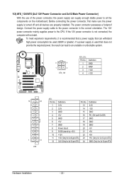
Connect the power supply cable to the CPU. To meet expansion requirements, it is turned off and all the components on the motherboard. The 12V power connector mainly supplies power to the power connector in the correct orientation. 1/2) ATX_12V/ATX (2x2 12V Power Connector and 2x12 Main Power ...
Connect the power supply cable to the CPU. To meet expansion requirements, it is turned off and all the components on the motherboard. The 12V power connector mainly supplies power to the power connector in the correct orientation. 1/2) ATX_12V/ATX (2x2 12V Power Connector and 2x12 Main Power ...

User Manual
Page 23
...8226; These fan headers are : 360 KB, 720 KB, 1.2 MB, 1.44 MB, and 2.88 MB. Hardware Installation 3/4/5) CPU_FAN/SYS_FAN1/SYS_FAN2/PWR_FAN (Fan Headers) The motherboard has a 4-pin CPU fan header (CPU_FAN), a 4-pin (SYS_FAN2) and a 3-pin (SYS_ FAN1) system fan headers, and a 3-pin power fan header (PWR_FAN). ...by a stripe of different color. Before connecting a floppy disk drive, be installed inside the chassis. CPU_FAN: Pin No. The motherboard supports CPU fan speed control, which requires the use of floppy disk drives supported are not configuration jumper blocks. Do not place a...
...8226; These fan headers are : 360 KB, 720 KB, 1.2 MB, 1.44 MB, and 2.88 MB. Hardware Installation 3/4/5) CPU_FAN/SYS_FAN1/SYS_FAN2/PWR_FAN (Fan Headers) The motherboard has a 4-pin CPU fan header (CPU_FAN), a 4-pin (SYS_FAN2) and a 3-pin (SYS_ FAN1) system fan headers, and a 3-pin power fan header (PWR_FAN). ...by a stripe of different color. Before connecting a floppy disk drive, be installed inside the chassis. CPU_FAN: Pin No. The motherboard supports CPU fan speed control, which requires the use of floppy disk drives supported are not configuration jumper blocks. Do not place a...

User Manual
Page 27
Incorrect connection between the module connector and the motherboard header will be present on both of the front and back panel audio connections simultaneously. Definition Pin No. If you want to mute the back ... In Connector) You may connect your chassis provides an AC'97 front panel audio module, refer to the instructions on each wire instead of the motherboard header. Make sure the wire assignments of the module connector match the pin assignments of a single plug. Pin No. Hardware Installation Definition 2 10 1 MIC2_L 1 MIC...
Incorrect connection between the module connector and the motherboard header will be present on both of the front and back panel audio connections simultaneously. Definition Pin No. If you want to mute the back ... In Connector) You may connect your chassis provides an AC'97 front panel audio module, refer to the instructions on each wire instead of the motherboard header. Make sure the wire assignments of the module connector match the pin assignments of a single plug. Pin No. Hardware Installation Definition 2 10 1 MIC2_L 1 MIC...

User Manual
Page 28
... supports digital S/PDIF Out and connects a S/PDIF digital audio cable (provided by expansion cards) for digital audio output from your motherboard to the graphics card and have digital audio output from your motherboard to your expansion card. 1 Pin No. For example, some graphics cards may require you to use a S/PDIF digital audio...
... supports digital S/PDIF Out and connects a S/PDIF digital audio cable (provided by expansion cards) for digital audio output from your motherboard to the graphics card and have digital audio output from your motherboard to your expansion card. 1 Pin No. For example, some graphics cards may require you to use a S/PDIF digital audio...


