User Manual
Page 7
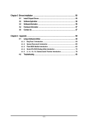
Chapter 3 Drivers Installation 55 3-1 Install Chipset Drivers 55 3-2 SoftwareApplication 56 3-3 Software Information 56 3-4 Hardware Information 57 3-5 Contact Us ...57 Chapter 4 Appendix 59 4-1 Unique Software Utilities 59 4-1-1 EasyTune 5 Introduction 59 4-1-2 Xpress Recovery2 Introduction 60 4-1-3 Flash BIOS Method Introduction 62 4-1-4 Serial ATA BIOS Setting Utility Introduction 73 4-1-5 2- / 4- / 6- / 8- Channel Audio Function Introduction 79 4-2 Troubleshooting 85 - 7 -
Chapter 3 Drivers Installation 55 3-1 Install Chipset Drivers 55 3-2 SoftwareApplication 56 3-3 Software Information 56 3-4 Hardware Information 57 3-5 Contact Us ...57 Chapter 4 Appendix 59 4-1 Unique Software Utilities 59 4-1-1 EasyTune 5 Introduction 59 4-1-2 Xpress Recovery2 Introduction 60 4-1-3 Flash BIOS Method Introduction 62 4-1-4 Serial ATA BIOS Setting Utility Introduction 73 4-1-5 2- / 4- / 6- / 8- Channel Audio Function Introduction 79 4-2 Troubleshooting 85 - 7 -
User Manual
Page 12
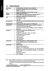
Center/Subwoofer Speaker Out ; Only for GA-K8N Pro-SLI. Only for GA-K8N Ultra-SLI. K8 nForce4 SLI Series Motherboard - 12 - Line Out (Front Speaker Out) ; MIC ; Surround Speaker Out (Rear Speaker Out) ; For example, 4 GB... function Š Supports 2 / 4 / 6 / 8 channel audio Š Supports Line In ; English 1-2 Feature Summary Motherboard CPU Chipset Memory Slots IDE Connections FDD Connections Onboard SATA Peripherals Onboard LAN Onboard Audio Š GA-K8N Ultra-SLI or GA-K8N Pro-SLI or GA-K8N-SLI Š Socket 939 for system usage and therefore the actual memory...
Center/Subwoofer Speaker Out ; Only for GA-K8N Pro-SLI. Only for GA-K8N Ultra-SLI. K8 nForce4 SLI Series Motherboard - 12 - Line Out (Front Speaker Out) ; MIC ; Surround Speaker Out (Rear Speaker Out) ; For example, 4 GB... function Š Supports 2 / 4 / 6 / 8 channel audio Š Supports Line In ; English 1-2 Feature Summary Motherboard CPU Chipset Memory Slots IDE Connections FDD Connections Onboard SATA Peripherals Onboard LAN Onboard Audio Š GA-K8N Ultra-SLI or GA-K8N Pro-SLI or GA-K8N-SLI Š Socket 939 for system usage and therefore the actual memory...

User Manual
Page 22
... your OS does not support USB controller, please contact OS vendor for GA-K8N Ultra-SLI. Only for possible patch or driver upgrade. Parallel Port The parallel port allows connection of providing digital audio to external speakers or compressed AC3 data to the lower port (purple). Also...speakers to MIC In jack. SPDIF_O (SPDIF Out) The SPDIF output is Gigabit Ethernet, providing data transfer speeds of 10/100/1000Mbps. K8 nForce4 SLI Series Motherboard - 22 - English 1-7 I/O Back Panel Introduction PS/2 Keyboard and PS/2 Mouse Connector To install a PS/2 port keyboard and mouse,...
... your OS does not support USB controller, please contact OS vendor for GA-K8N Ultra-SLI. Only for possible patch or driver upgrade. Parallel Port The parallel port allows connection of providing digital audio to external speakers or compressed AC3 data to the lower port (purple). Also...speakers to MIC In jack. SPDIF_O (SPDIF Out) The SPDIF output is Gigabit Ethernet, providing data transfer speeds of 10/100/1000Mbps. K8 nForce4 SLI Series Motherboard - 22 - English 1-7 I/O Back Panel Introduction PS/2 Keyboard and PS/2 Mouse Connector To install a PS/2 port keyboard and mouse,...
User Manual
Page 23
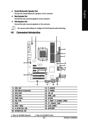
... Out Connect the rear surround speakers to configure 2-/4-/6-/8-channel audio functioning. 1-8 Connectors Introduction 13 8 11 13 1) ATX_12V 2) ATX (Power Connector) 3) CPU_FAN 4) SYS_FAN 5) PWR_FAN 6) NB_FAN 7) FDD 8) IDE1 / IDE2 9) S_ATA0/1/2/3_SB 10) SATA0/1/2/3_SII Only for GA-K8N Ultra-SLI. 2 5 7 19 6 18 9 12 14 ... IR/CIR 16) F_USB1 / F_USB2/F_USB3 17) F1_1394/F2_1394 18) CLR_CMOS 19) BATTERY Only for GA-K8N Pro-SLI. - 23 - You can use audio software to this connector. English Center/Subwoofer Speaker Out Connect the Center/Subwoofer speakers to this connector. Side Speaker...
... Out Connect the rear surround speakers to configure 2-/4-/6-/8-channel audio functioning. 1-8 Connectors Introduction 13 8 11 13 1) ATX_12V 2) ATX (Power Connector) 3) CPU_FAN 4) SYS_FAN 5) PWR_FAN 6) NB_FAN 7) FDD 8) IDE1 / IDE2 9) S_ATA0/1/2/3_SB 10) SATA0/1/2/3_SII Only for GA-K8N Ultra-SLI. 2 5 7 19 6 18 9 12 14 ... IR/CIR 16) F_USB1 / F_USB2/F_USB3 17) F1_1394/F2_1394 18) CLR_CMOS 19) BATTERY Only for GA-K8N Pro-SLI. - 23 - You can use audio software to this connector. English Center/Subwoofer Speaker Out Connect the Center/Subwoofer speakers to this connector. Side Speaker...
User Manual
Page 27
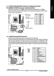
... up to 150MB/s transfer rate. Please refer to the BIOS setting for GA-K8N Ultra-SLI. - 27 - To find out if the chassis you are buying support front audio connector, please contact your chassis must remove 5-6, 9-10 Jumper. Hardware Installation English...2 3 4 5 6 7 8 9 10 Definition MIC GND MIC_BIAS Power Front Audio (R) Rear Audio (R)/ Return R NC No Pin Front Audio (L) Rear Audio (L)/ Return L Only for the Serial ATA controller(s)and install the proper driver in order to work properly. 7 1 S_ATA_SB (Controlled by nForce4 SLI) 7 1 Pin No. 1 2 3 4 5 6 7 Definition GND TXP...
... up to 150MB/s transfer rate. Please refer to the BIOS setting for GA-K8N Ultra-SLI. - 27 - To find out if the chassis you are buying support front audio connector, please contact your chassis must remove 5-6, 9-10 Jumper. Hardware Installation English...2 3 4 5 6 7 8 9 10 Definition MIC GND MIC_BIAS Power Front Audio (R) Rear Audio (R)/ Return R NC No Pin Front Audio (L) Rear Audio (L)/ Return L Only for the Serial ATA controller(s)and install the proper driver in order to work properly. 7 1 S_ATA_SB (Controlled by nForce4 SLI) 7 1 Pin No. 1 2 3 4 5 6 7 Definition GND TXP...

User Manual
Page 29
Definition 1 1 CD-L 2 GND 3 GND 4 CD-R 14) PWR_LED PWR_LED is connect with the system power indicator to the connector. English 13) CD_IN (CD In Connector) Connect CD-ROM or DVD-ROM audio out to indicate whether the system is on/off. Pin No. Definition 1 MPD+ 2 MPD- 1 3 MPD- - 29 - Pin No. Hardware Installation It will blink when the system enters suspend mode.
Definition 1 1 CD-L 2 GND 3 GND 4 CD-R 14) PWR_LED PWR_LED is connect with the system power indicator to the connector. English 13) CD_IN (CD In Connector) Connect CD-ROM or DVD-ROM audio out to indicate whether the system is on/off. Pin No. Definition 1 MPD+ 2 MPD- 1 3 MPD- - 29 - Pin No. Hardware Installation It will blink when the system enters suspend mode.
User Manual
Page 40
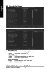
Only for GA-K8N Ultra-SLI. F1: General Help Only for GA-K8N Pro-SLI. English 2-3 Integrated Peripherals CMOS Setup Utility-Copyright (C) 1984-2005 Award Software Integrated Peripherals On-Chip IDE Channel0 On-Chip IDE Channel1 IDE DMA ...: Save ESC: Exit F7: Optimized Defaults F1: General Help CMOS Setup Utility-Copyright (C) 1984-2005 Award Software Integrated Peripherals USB Memory Type AC97 Audio Onboard 139412 Onboard LAN control1 OnBoard LAN Boot ROM1 SATA RAID-5/ATA controller1 SATA controller Function1 Onboard Serial Port 1 Onboard IrDA Port Onboard Parallel Port...
Only for GA-K8N Ultra-SLI. F1: General Help Only for GA-K8N Pro-SLI. English 2-3 Integrated Peripherals CMOS Setup Utility-Copyright (C) 1984-2005 Award Software Integrated Peripherals On-Chip IDE Channel0 On-Chip IDE Channel1 IDE DMA ...: Save ESC: Exit F7: Optimized Defaults F1: General Help CMOS Setup Utility-Copyright (C) 1984-2005 Award Software Integrated Peripherals USB Memory Type AC97 Audio Onboard 139412 Onboard LAN control1 OnBoard LAN Boot ROM1 SATA RAID-5/ATA controller1 SATA controller Function1 Onboard Serial Port 1 Onboard IrDA Port Onboard Parallel Port...
User Manual
Page 42
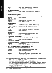
...connector , please set "NV SATA1/NV SATA 2 class code" from 0101 to enable or disable the Sil3114 controller. Only for GA-K8N Ultra-SLI. SATA controller Function (Controlled by Sil3114 chip) This option is connected to the SATA0 or SATA1 connector , please set "NV SATA1 ...to 0104. on the RAID drive. If your SATA hard drive is to 0104. K8 nForce4 SLI Series Motherboard - 42 - Only for GA-K8N Pro-SLI. AC97 Audio Auto Disabled Enable onboard AC'97 audio function. (Default value) Disable this function. Enabled Enable onboard Serial ATA Chip.(Default value) ...
...connector , please set "NV SATA1/NV SATA 2 class code" from 0101 to enable or disable the Sil3114 controller. Only for GA-K8N Ultra-SLI. SATA controller Function (Controlled by Sil3114 chip) This option is connected to the SATA0 or SATA1 connector , please set "NV SATA1 ...to 0104. on the RAID drive. If your SATA hard drive is to 0104. K8 nForce4 SLI Series Motherboard - 42 - Only for GA-K8N Pro-SLI. AC97 Audio Auto Disabled Enable onboard AC'97 audio function. (Default value) Disable this function. Enabled Enable onboard Serial ATA Chip.(Default value) ...
User Manual
Page 79
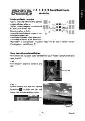
... channels to Cen- Line Out STEP 2 : Following installation of audio connectors: You may connect CD-ROM/DVD-ROM, walkman or others audio input to Line In. Appendix Channel Audio Function Introduction Introduction of the audio driver, you use the speaker with amplifier to "Line Out". ... Connect microphone to select the function. - 79 - Click the icon to Mic In. English 4-1-5 2- / 4- / 6- / 8- The installation of audio software is applied. STEP 1: Connect the stereo speakers or earphone to acquire the best sound effect if the stereo output is very simple.
... channels to Cen- Line Out STEP 2 : Following installation of audio connectors: You may connect CD-ROM/DVD-ROM, walkman or others audio input to Line In. Appendix Channel Audio Function Introduction Introduction of the audio driver, you use the speaker with amplifier to "Line Out". ... Connect microphone to select the function. - 79 - Click the icon to Mic In. English 4-1-5 2- / 4- / 6- / 8- The installation of audio software is applied. STEP 1: Connect the stereo speakers or earphone to acquire the best sound effect if the stereo output is very simple.
User Manual
Page 80
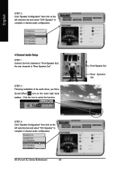
...bar and select "4CH Speaker" to complete 4 channel audio configuration. Click the icon to "Rear Speaker Out". STEP 3: Click "Speaker Configuration" then click on the lower right hand taskbar. STEP 2 : Following installation of the audio driver, you find a Sound Effect icon on the left... selection bar and select "2CH Speaker" to complete 2 channel audio configuration. 4 Channel Audio Setup STEP 1 : Connect the front channels to "Front Speaker Out", the ...
...bar and select "4CH Speaker" to complete 4 channel audio configuration. Click the icon to "Rear Speaker Out". STEP 3: Click "Speaker Configuration" then click on the lower right hand taskbar. STEP 2 : Following installation of the audio driver, you find a Sound Effect icon on the left... selection bar and select "2CH Speaker" to complete 2 channel audio configuration. 4 Channel Audio Setup STEP 1 : Connect the front channels to "Front Speaker Out", the ...

User Manual
Page 81
Appendix Click the icon to complete 6 channel audio configuration. STEP 3: Click "Speaker Configuration" then click on the lower right hand taskbar. English 6 Channel Audio Setup STEP 1 : Connect the front channels to "Front Speaker Out", the rear channels to "Rear Speaker Out", and the Center/Subwoofer channels to "Center/Subwoofer Speaker Out". STEP 2 : Following installation of the audio driver, you find a Sound Effect icon on the left selection bar and select "6CH Speaker" to select the function. Front Speaker Out Center/Subwoofer Speaker Out Rear Speaker Out - 81 -
Appendix Click the icon to complete 6 channel audio configuration. STEP 3: Click "Speaker Configuration" then click on the lower right hand taskbar. English 6 Channel Audio Setup STEP 1 : Connect the front channels to "Front Speaker Out", the rear channels to "Rear Speaker Out", and the Center/Subwoofer channels to "Center/Subwoofer Speaker Out". STEP 2 : Following installation of the audio driver, you find a Sound Effect icon on the left selection bar and select "6CH Speaker" to select the function. Front Speaker Out Center/Subwoofer Speaker Out Rear Speaker Out - 81 -

User Manual
Page 82
Front Speaker Out Center/Subwoofer Speaker Out Rear Speaker Out Side Speaker Out K8 nForce4 SLI Series Motherboard - 82 - Click the icon to complete 8 channel audio configuration. STEP 2 : Following installation of the audio driver, you find a Sound Effect icon on the left selection bar and select "...8CH Speaker" to select the function. STEP 3: Click "Speaker Configuration" then click on the lower right hand taskbar. English 8 Channel Audio Setup STEP 1 : Connect the front channels to "Front Speaker Out", the rear channels to "Rear Speaker Out", the Center/Subwoofer channels ...
Front Speaker Out Center/Subwoofer Speaker Out Rear Speaker Out Side Speaker Out K8 nForce4 SLI Series Motherboard - 82 - Click the icon to complete 8 channel audio configuration. STEP 2 : Following installation of the audio driver, you find a Sound Effect icon on the left selection bar and select "...8CH Speaker" to select the function. STEP 3: Click "Speaker Configuration" then click on the lower right hand taskbar. English 8 Channel Audio Setup STEP 1 : Connect the front channels to "Front Speaker Out", the rear channels to "Rear Speaker Out", the Center/Subwoofer channels ...
User Manual
Page 83
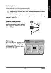
... will appear as above. Jack-Sensing includes 2 parts: AUTO and MANUAL. A window will only appear when 3D audio inputs. - 83 - Following is an example for Windows 98/ 98SE/ 2000/ ME. Install Microsoft DirectX8.1 or later version before to enable Jack-Sensing support ...for 2 channels (Following pictures are in Windows XP): Introduction of audio connectors You may connect CDROM, Walkman or others audio input devices to Line In jack, speakers, earphone or others output devices to Line Out jack, and microphone to the right...
... will appear as above. Jack-Sensing includes 2 parts: AUTO and MANUAL. A window will only appear when 3D audio inputs. - 83 - Following is an example for Windows 98/ 98SE/ 2000/ ME. Install Microsoft DirectX8.1 or later version before to enable Jack-Sensing support ...for 2 channels (Following pictures are in Windows XP): Introduction of audio connectors You may connect CDROM, Walkman or others audio input devices to Line In jack, speakers, earphone or others output devices to Line Out jack, and microphone to the right...


