Manual
Page 7
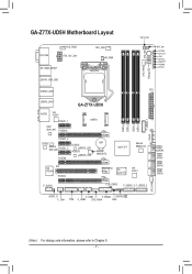
... LED (Note) ATX USB30_LAN1 AUDIO VIA VL810 PCIEX1_1 Intel® GbE LAN PCIEX16 GA-Z77X-UD5H mSATA PCIEX1_2 CODEC Atheros GbE LAN PCIEX1_3 PCIEX8 B_BIOS BBIOS_LED M_BIOS MBIOS_LED BAT Marvell 88SE9172 Intel® Z77 Marvell 88SE9172 VIA PCI VT6308 PCIEX4 PCIe to PCI Bridge iTE Super I/O VIA VL810 F_AUDIO CLR_CMOS F_USB30_3 F_USB30_2 DDR3_4 DDR3_2...
... LED (Note) ATX USB30_LAN1 AUDIO VIA VL810 PCIEX1_1 Intel® GbE LAN PCIEX16 GA-Z77X-UD5H mSATA PCIEX1_2 CODEC Atheros GbE LAN PCIEX1_3 PCIEX8 B_BIOS BBIOS_LED M_BIOS MBIOS_LED BAT Marvell 88SE9172 Intel® Z77 Marvell 88SE9172 VIA PCI VT6308 PCIEX4 PCIe to PCI Bridge iTE Super I/O VIA VL810 F_AUDIO CLR_CMOS F_USB30_3 F_USB30_2 DDR3_4 DDR3_2...
Manual
Page 8
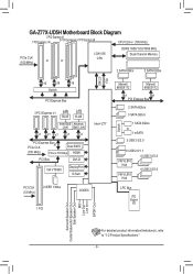
GA-Z77X-UD5H Motherboard Block Diagram 2 PCI Express x8 1 PCI Express x16 2 PCI Express x4+1 PCI Express x8 CPU CLK+/- (100 MHz) PCIe CLK (100 MHz) or or LGA1155 CPU DDR3 1600/1333/1066 MHz Dual Channel Memory 2 SATA 6Gb/s 2 SATA 6Gb/s DMI 2.0 FDI x16 x16 x16 Switch ... Express Bus 3 PCI Express x1 LAN LAN RJ45 RJ45 Intel GbE Atheros LAN GbE LAN x1 x1 x1 x1 x1 PCI Express Busx1 PCIe CLK Dual BIOS (100 MHz) PCIe to PCI Bridge HDMI PCI Bus DVI-D VIA VT6308 DisplayPort D-Sub Intel® Z77 PCI CLK (33 MHz) 2 IEEE 1394a CODEC 1 PCI...
GA-Z77X-UD5H Motherboard Block Diagram 2 PCI Express x8 1 PCI Express x16 2 PCI Express x4+1 PCI Express x8 CPU CLK+/- (100 MHz) PCIe CLK (100 MHz) or or LGA1155 CPU DDR3 1600/1333/1066 MHz Dual Channel Memory 2 SATA 6Gb/s 2 SATA 6Gb/s DMI 2.0 FDI x16 x16 x16 Switch ... Express Bus 3 PCI Express x1 LAN LAN RJ45 RJ45 Intel GbE Atheros LAN GbE LAN x1 x1 x1 x1 x1 PCI Express Busx1 PCIe CLK Dual BIOS (100 MHz) PCIe to PCI Bridge HDMI PCI Bus DVI-D VIA VT6308 DisplayPort D-Sub Intel® Z77 PCI CLK (33 MHz) 2 IEEE 1394a CODEC 1 PCI...
Manual
Page 11
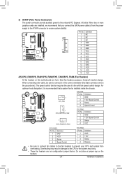
... 3.0/2.0 ports (4 ports on the back panel, 4 ports available through the internal IEEE 1394a header) 1 x 24-pin ATX main power connector 1 x 8-pin ATX 12V power connector 1 x PCIe power connector 5 x SATA 6Gb/s connectors 4 x SATA 3Gb/s connectors 1 x mSATA connector 1 x CPU fan header 4 x system fan headers 1 x front panel header 1 x front panel audio header 1 x S/PDIF Out...
... 3.0/2.0 ports (4 ports on the back panel, 4 ports available through the internal IEEE 1394a header) 1 x 24-pin ATX main power connector 1 x 8-pin ATX 12V power connector 1 x PCIe power connector 5 x SATA 6Gb/s connectors 4 x SATA 3Gb/s connectors 1 x mSATA connector 1 x CPU fan header 4 x system fan headers 1 x front panel header 1 x front panel audio header 1 x S/PDIF Out...

Manual
Page 24
... 1 23 DIP 1 23 DIP 1 23 DIP 1 23 2 GND Voltage measurement points(G1.Sniper 3) VSA BIOS Switcher (SW4) PCIe power connector (SATA)(X58A-OC) Pin 1 Voltage measurement points(G1.Sniper 3) CPUPLL BIOS Switcher (SW4) Pin 1 Voltage measurement points(... Voltage Measurement PointsTwP/hMousing VoltDagBe_PmOeRasTurement module(X58A-OC) VoltDagBe_PmOeRasTurement module(X58A-OC) PCIe power connector (SATA)(X58A-OC) VoltDagBe_PmOeRasTurement module(X58A-OC) PCIe power connector (SATA)(X58A-OC) VoltDagBe_PmOeRasTurement module(X58A-OC) PCIe power connector (SATA)(X58A-OC) DIP 1 23 1 DIP 1 23 ...
... 1 23 DIP 1 23 DIP 1 23 DIP 1 23 2 GND Voltage measurement points(G1.Sniper 3) VSA BIOS Switcher (SW4) PCIe power connector (SATA)(X58A-OC) Pin 1 Voltage measurement points(G1.Sniper 3) CPUPLL BIOS Switcher (SW4) Pin 1 Voltage measurement points(... Voltage Measurement PointsTwP/hMousing VoltDagBe_PmOeRasTurement module(X58A-OC) VoltDagBe_PmOeRasTurement module(X58A-OC) PCIe power connector (SATA)(X58A-OC) VoltDagBe_PmOeRasTurement module(X58A-OC) PCIe power connector (SATA)(X58A-OC) VoltDagBe_PmOeRasTurement module(X58A-OC) PCIe power connector (SATA)(X58A-OC) DIP 1 23 1 DIP 1 23 ...
Manual
Page 27
.... •• These fan headers are 4-pin. BIOS Switcher (X58A-OC) 1 M_SATA F_PANEL(NH) PWM Switch (X58A-OC) DIP 1 23 PCIe power connector (SATA)(X58A-OC) DIP 1 23 1 DIP 1 23 1 3) ATX4P (PCIe Power Connector) The power connector provide auxiliary powDeIPr to connect it is the ground wire). CPU_FAN: Pin No. Overheating may...
.... •• These fan headers are 4-pin. BIOS Switcher (X58A-OC) 1 M_SATA F_PANEL(NH) PWM Switch (X58A-OC) DIP 1 23 PCIe power connector (SATA)(X58A-OC) DIP 1 23 1 DIP 1 23 1 3) ATX4P (PCIe Power Connector) The power connector provide auxiliary powDeIPr to connect it is the ground wire). CPU_FAN: Pin No. Overheating may...

Manual
Page 33
...optional USB bracket, please contact the local dealer. Hardware Installation Voltage measurement points(G1.Sniper 3) BIOS Switcher (SW4) F_AUDIO(H) DB_PORT Voltage measurement module(X58A-OC) PCIe power connector (SATA)(X58A-O Definition 1 VBUS 11 D2+ 2 SSRX1- 11 3 SSRX1+ 12 D213 GND 4 GND 14 SSTX2+ 5 SSTX1- 15 SSTX2-... 11 F_USB30 TPM w/housing BIOS Switcher (X58A-O 1 PWM Switch (X58A-O DIP 1 23 1 DIP 1 23 1 DIP 1 23 1 DIP 1 23 PCIe power connector (SATA)(X58A-OC) •• Do not plug the IEEE 1394 bracket (2x5-pin) cable into a free 3.5" drive bay of your computer...
...optional USB bracket, please contact the local dealer. Hardware Installation Voltage measurement points(G1.Sniper 3) BIOS Switcher (SW4) F_AUDIO(H) DB_PORT Voltage measurement module(X58A-OC) PCIe power connector (SATA)(X58A-O Definition 1 VBUS 11 D2+ 2 SSRX1- 11 3 SSRX1+ 12 D213 GND 4 GND 14 SSTX2+ 5 SSTX1- 15 SSTX2-... 11 F_USB30 TPM w/housing BIOS Switcher (X58A-O 1 PWM Switch (X58A-O DIP 1 23 1 DIP 1 23 1 DIP 1 23 1 DIP 1 23 PCIe power connector (SATA)(X58A-OC) •• Do not plug the IEEE 1394 bracket (2x5-pin) cable into a free 3.5" drive bay of your computer...

Manual
Page 34
... sure to turn off your computer and then attach the other end of the cable to this header. Definition LCLK GND 11 LAD0 12 GND PCIe power connector (SATA)(X58A-OC) LFRAME 13 NC No Pin 14 ID LRESET 15 SB3V NC 16 SERIRQ LAD3 17 GND LAD2 18 NC VCC3...
... sure to turn off your computer and then attach the other end of the cable to this header. Definition LCLK GND 11 LAD0 12 GND PCIe power connector (SATA)(X58A-OC) LFRAME 13 NC No Pin 14 ID LRESET 15 SB3V NC 16 SERIRQ LAD3 17 GND LAD2 18 NC VCC3...

Manual
Page 42
... adjustable range is from 400 MHz to 3200 MHz. (Default: Auto) && CPU Clock Ratio Allows you to manually set the CPU base clock and PCIe bus frequency in 0.01 MHz increments. (Default: Auto) Important: It is dependent on CPU/memory frequencies/parameters. `` Advanced Frequency Settings && CPU.../PCIe Base Clock Allows you to set in accordance with the CPU specifications. && Internal Graphics Clock Allows you to alter the clock ratio for the...
... adjustable range is from 400 MHz to 3200 MHz. (Default: Auto) && CPU Clock Ratio Allows you to manually set the CPU base clock and PCIe bus frequency in 0.01 MHz increments. (Default: Auto) Important: It is dependent on CPU/memory frequencies/parameters. `` Advanced Frequency Settings && CPU.../PCIe Base Clock Allows you to set in accordance with the CPU specifications. && Internal Graphics Clock Allows you to alter the clock ratio for the...

Manual
Page 94
BIOS Version 1.0.1.0025 PCIe x2 5.0Gbps Mode: RAID [Virtual Disks] No Virtual Disk! [Physical Disks] Adapter 0 Port Disk Name S0 SATA: WDC WD800JD-22LSA0 S1 SATA: WDC WD800JD-22LSA0 ...
BIOS Version 1.0.1.0025 PCIe x2 5.0Gbps Mode: RAID [Virtual Disks] No Virtual Disk! [Physical Disks] Adapter 0 Port Disk Name S0 SATA: WDC WD800JD-22LSA0 S1 SATA: WDC WD800JD-22LSA0 ...


