User Manual
Page 2
Motherboard GA-Z77X-UD3H Mar. 16, 2012 Motherboard GA-Z77X-UD3H Mar. 16, 2012
Motherboard GA-Z77X-UD3H Mar. 16, 2012 Motherboard GA-Z77X-UD3H Mar. 16, 2012
User Manual
Page 3
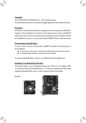
...their respective owners. For product-related information, check on our website at: http://www.gigabyte.com Identifying Your Motherboard Revision The revision number on your motherboard revision before updating motherboard BIOS, drivers, or when looking for technical information. All rights reserved. Example: ...Copyright © 2012 GIGA-BYTE TECHNOLOGY CO., LTD. For example, "REV: 1.0" means the revision of the motherboard is the property of this manual may be reproduced, copied, translated, transmitted, orpublished in this : "REV: X.X." The trademarks mentioned...
...their respective owners. For product-related information, check on our website at: http://www.gigabyte.com Identifying Your Motherboard Revision The revision number on your motherboard revision before updating motherboard BIOS, drivers, or when looking for technical information. All rights reserved. Example: ...Copyright © 2012 GIGA-BYTE TECHNOLOGY CO., LTD. For example, "REV: 1.0" means the revision of the motherboard is the property of this manual may be reproduced, copied, translated, transmitted, orpublished in this : "REV: X.X." The trademarks mentioned...
User Manual
Page 4
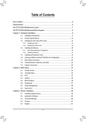
Table of Contents Box Contents...6 Optional Items...6 GA-Z77X-UD3H Motherboard Layout 7 GA-Z77X-UD3H Motherboard Block Diagram 8 Chapter 1 Hardware Installation 9 1-1 Installation Precautions 9 1-2 Product Specifications 10 1-3 Installing the CPU and CPU Cooler 13 1-3-1 Installing the CPU 13 1-3-2 Installing the CPU Cooler ...
Table of Contents Box Contents...6 Optional Items...6 GA-Z77X-UD3H Motherboard Layout 7 GA-Z77X-UD3H Motherboard Block Diagram 8 Chapter 1 Hardware Installation 9 1-1 Installation Precautions 9 1-2 Product Specifications 10 1-3 Installing the CPU and CPU Cooler 13 1-3-1 Installing the CPU 13 1-3-2 Installing the CPU Cooler ...

User Manual
Page 6
Box Contents 55 GA-Z77X-UD3H motherboard 55 Motherboard driver disk 55 User's Manual 55 Quick Installation Guide 55 Four SATA 6Gb/s cables 55 I/O Shield 55 One 2-Way SLI bridge connector 55 One GC-WB150D (including two antennas, one USB 2.0 cable, driver disk, and user's manual)j MM Only for GA-Z77X-UD3H The box contents above are subject to...
Box Contents 55 GA-Z77X-UD3H motherboard 55 Motherboard driver disk 55 User's Manual 55 Quick Installation Guide 55 Four SATA 6Gb/s cables 55 I/O Shield 55 One 2-Way SLI bridge connector 55 One GC-WB150D (including two antennas, one USB 2.0 cable, driver disk, and user's manual)j MM Only for GA-Z77X-UD3H The box contents above are subject to...
User Manual
Page 7
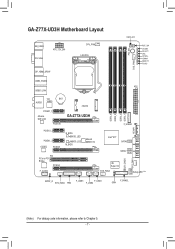
GA-Z77X-UD3H Motherboard Layout KB_USB3 DVI VGA ATX_12V_2X4 DP_HDMI_SPDIF CPU_FAN LGA1155 SYS_FAN2 PW_SW CMOS_SW RST_SW VCORE CPUVTT VSA CPUPLL VDIMM DDRVTT PCHIO USB3_ESATA ATX USB30_LAN VIA BAT AUDIO VL800 PCIEX1_1 Atheros GbE LAN PCIEX16 mSATA GA-Z77X-UD3H PCIEX1_2 PCIEX1_3 CODEC PCIEX8 B_BIOS BBIOS_LED MBIOS_LED M_BIOS Marvell 88SE9172 PCI PCIe to PCI Bridge PCIEX4 F_AUDIO DDR3_4 DDR3_2...
GA-Z77X-UD3H Motherboard Layout KB_USB3 DVI VGA ATX_12V_2X4 DP_HDMI_SPDIF CPU_FAN LGA1155 SYS_FAN2 PW_SW CMOS_SW RST_SW VCORE CPUVTT VSA CPUPLL VDIMM DDRVTT PCHIO USB3_ESATA ATX USB30_LAN VIA BAT AUDIO VL800 PCIEX1_1 Atheros GbE LAN PCIEX16 mSATA GA-Z77X-UD3H PCIEX1_2 PCIEX1_3 CODEC PCIEX8 B_BIOS BBIOS_LED MBIOS_LED M_BIOS Marvell 88SE9172 PCI PCIe to PCI Bridge PCIEX4 F_AUDIO DDR3_4 DDR3_2...
User Manual
Page 8
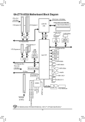
GA-Z77X-UD3H Motherboard Block Diagram PCIe CLK (100 MHz) 1 PCI Express x16 or 2 PCI Express x8 LGA1155 CPU CPU CLK+/- (100 MHz) DDR3 1600/1333/1066 MHz Dual ...
GA-Z77X-UD3H Motherboard Block Diagram PCIe CLK (100 MHz) 1 PCI Express x16 or 2 PCI Express x8 LGA1155 CPU CPU CLK+/- (100 MHz) DDR3 1600/1333/1066 MHz Dual ...
User Manual
Page 9
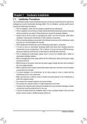
... remove the AC power by your hands dry and first touch a metal object to eliminate static electricity. •• Prior to installing the motherboard, please have a problem related to wear an electrostatic discharge (ESD) wrist strap when handling electronic components such as physical harm to the user.... it on top of an antistatic pad or within an electrostatic shielding container. •• Before unplugging the power supply cable from the motherboard, make sure the power supply has been turned off. •• Before turning on the power, make sure the power supply voltage...
... remove the AC power by your hands dry and first touch a metal object to eliminate static electricity. •• Prior to installing the motherboard, please have a problem related to wear an electrostatic discharge (ESD) wrist strap when handling electronic components such as physical harm to the user.... it on top of an antistatic pad or within an electrostatic shielding container. •• Before unplugging the power supply cable from the motherboard, make sure the power supply has been turned off. •• Before turning on the power, make sure the power supply voltage...
User Manual
Page 12
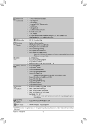
... eXtreme Hard Drive (X.H.D) Support for Auto Green Support for ON/OFF Charge Support for Q-Share Support for EasyTune * Available functions in EasyTune may differ by motherboard model.
... eXtreme Hard Drive (X.H.D) Support for Auto Green Support for ON/OFF Charge Support for Q-Share Support for EasyTune * Available functions in EasyTune may differ by motherboard model.
User Manual
Page 13
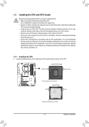
... latest CPU support list.) •• Always turn on the computer if the CPU cooler is not recommended that the motherboard supports the CPU. (Go to GIGABYTE's website for the peripherals. LGA1155 CPU Socket Alignment Key Alignment Key Pin One Corner of the CPU. It is not ...may occur. •• Set the CPU host frequency in accordance with the CPU specifications. Hardware Installation Locate the alignment keys on the motherboard CPU socket and the notches on the CPU - 13 - 1-3 Installing the CPU and CPU Cooler Read the following guidelines before installing the...
... latest CPU support list.) •• Always turn on the computer if the CPU cooler is not recommended that the motherboard supports the CPU. (Go to GIGABYTE's website for the peripherals. LGA1155 CPU Socket Alignment Key Alignment Key Pin One Corner of the CPU. It is not ...may occur. •• Set the CPU host frequency in accordance with the CPU specifications. Hardware Installation Locate the alignment keys on the motherboard CPU socket and the notches on the CPU - 13 - 1-3 Installing the CPU and CPU Cooler Read the following guidelines before installing the...
User Manual
Page 14
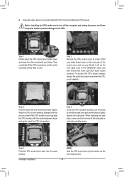
... socket lever and use your thumb to lift up the front edge (next to the CPU. Step 5: Push the CPU socket lever back into the motherboard CPU socket. Then completely lift the CPU socket lever and the metal load plate will be lifted as shown. Step 2: Remove the CPU socket cover...
... socket lever and use your thumb to lift up the front edge (next to the CPU. Step 5: Push the CPU socket lever back into the motherboard CPU socket. Then completely lift the CPU socket lever and the metal load plate will be lifted as shown. Step 2: Remove the CPU socket cover...
User Manual
Page 15
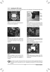
...the Male and Female push pins are joined closely. (Refer to your CPU cooler installation manual for instructions on the motherboard. Step 4: You should hear a "click" when pushing down on the motherboard. If the push pin is inserted as the example cooler.) Direction of the Arrow Sign on the Male Push ...Pin The Top of Female Push Pin Female Push Pin Step 1: Apply an even and thin layer of thermal grease on the surface of the motherboard. Inadequately removing the CPU cooler may adhere to the CPU. Use extreme care when removing the CPU cooler because the thermal grease/tape between ...
...the Male and Female push pins are joined closely. (Refer to your CPU cooler installation manual for instructions on the motherboard. Step 4: You should hear a "click" when pushing down on the motherboard. If the push pin is inserted as the example cooler.) Direction of the Arrow Sign on the Male Push ...Pin The Top of Female Push Pin Female Push Pin Step 1: Apply an even and thin layer of thermal grease on the surface of the motherboard. Inadequately removing the CPU cooler may adhere to the CPU. Use extreme care when removing the CPU cooler because the thermal grease/tape between ...
User Manual
Page 16
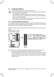
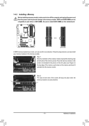
...memory mode will automatically detect the specifications and capacity of the same capacity, brand, speed, and chips be used . (Go to GIGABYTE's website for the latest supported memory speeds and memory modules.) •• Always turn off the computer and unplug the power cord ...memory sockets as following guidelines before installing the memory to insert the memory, switch the direction. 1-4-1 Dual Channel Memory Configuration This motherboard provides four DDR3 memory sockets and supports Dual Channel Technology. The four DDR3 memory sockets are unable to prevent hardware damage. &#...
...memory mode will automatically detect the specifications and capacity of the same capacity, brand, speed, and chips be used . (Go to GIGABYTE's website for the latest supported memory speeds and memory modules.) •• Always turn off the computer and unplug the power cord ...memory sockets as following guidelines before installing the memory to insert the memory, switch the direction. 1-4-1 Dual Channel Memory Configuration This motherboard provides four DDR3 memory sockets and supports Dual Channel Technology. The four DDR3 memory sockets are unable to prevent hardware damage. &#...
User Manual
Page 17
..., make sure to turn off the computer and unplug the power cord from the power outlet to prevent damage to install DDR3 DIMMs on this motherboard. Notch DDR3 DIMM A DDR3 memory module has a notch, so it vertically into place when the memory module is securely inserted. - 17...
..., make sure to turn off the computer and unplug the power cord from the power outlet to prevent damage to install DDR3 DIMMs on this motherboard. Notch DDR3 DIMM A DDR3 memory module has a notch, so it vertically into place when the memory module is securely inserted. - 17...
User Manual
Page 18
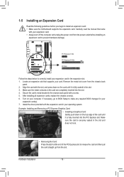
... off the computer and unplug the power cord from the power outlet before you begin to install an expansion card: •• Make sure the motherboard supports the expansion card. Locate an expansion slot that came with the expansion card in the slot and does not rock. •• Removing the...
... off the computer and unplug the power cord from the power outlet before you begin to install an expansion card: •• Make sure the motherboard supports the expansion card. Locate an expansion slot that came with the expansion card in the slot and does not rock. •• Removing the...
User Manual
Page 19
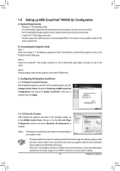
1-6 Setting up AMD CrossFireX™/NVIDIA SLI Configuration A. A CrossFireX/SLI-supported motherboard with your graphics cards for the power requirement) B. A power supply with sufficient power is recommended (Refer to the Catalyst Control Center. Step 3: Plug the display ...
1-6 Setting up AMD CrossFireX™/NVIDIA SLI Configuration A. A CrossFireX/SLI-supported motherboard with your graphics cards for the power requirement) B. A power supply with sufficient power is recommended (Refer to the Catalyst Control Center. Step 3: Plug the display ...
User Manual
Page 20
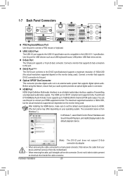
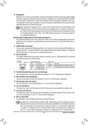
... Connectors PS/2 Keyboard/Mouse Port Use this port to a back panel connector, first remove the cable from your device and then remove it from the motherboard. •• When removing the cable, pull it side to side to an external audio system that your HDMI-supported monitor. The screenshot below is...
... Connectors PS/2 Keyboard/Mouse Port Use this port to a back panel connector, first remove the cable from your device and then remove it from the motherboard. •• When removing the cable, pull it side to side to an external audio system that your HDMI-supported monitor. The screenshot below is...
User Manual
Page 21
... for sound playback is one of the LAN port LEDs. After installing the DisplayPort device, make sure the default device for the Onboard Graphics: This motherboard provides four video output ports: D-Sub, DVI-D, HDMI, and DisplayPort. For example, in jack. Dual monitor confgurations are supported in Chapter 5, "Configuring 2/4/5.1/7.1-Channel Audio." - 21...
... for sound playback is one of the LAN port LEDs. After installing the DisplayPort device, make sure the default device for the Onboard Graphics: This motherboard provides four video output ports: D-Sub, DVI-D, HDMI, and DisplayPort. For example, in jack. Dual monitor confgurations are supported in Chapter 5, "Configuring 2/4/5.1/7.1-Channel Audio." - 21...
User Manual
Page 24
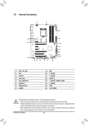
... 9) BAT 10) F_PANEL 11) F_AUDIO 12) SPDIF_O 13) F_USB1/F_USB2/F_USB3 14) F_USB30 15) TPM 16) CLR_CMOS Read the following guidelines before turning on the motherboard. Hardware Installation - 24 -
... 9) BAT 10) F_PANEL 11) F_AUDIO 12) SPDIF_O 13) F_USB1/F_USB2/F_USB3 14) F_USB30 15) TPM 16) CLR_CMOS Read the following guidelines before turning on the motherboard. Hardware Installation - 24 -
User Manual
Page 25
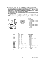
... can supply enough stable power to all devices are properly installed. To meet expansion requirements, it is turned off and all the components on the motherboard. Connect the power supply cable to the CPU. If a power supply is not connected, the computer will not start. Definition 1 GND (Only for 2x4-pin...
... can supply enough stable power to all devices are properly installed. To meet expansion requirements, it is turned off and all the components on the motherboard. Connect the power supply cable to the CPU. If a power supply is not connected, the computer will not start. Definition 1 GND (Only for 2x4-pin...

User Manual
Page 26
... the chassis. 1 CPU_FAN CPU_FAN: Pin No. Definition 1 GND 2 +12V /Speed Control 3 Sense 4 Reserve 1 SYS_FAN3/SYS_FAN4 SYS_FAN4: Pin No. Do not place a jumper cap on this motherboard are not configuration jumper blocks. Hardware Installation - 26 - For optimum heat dissipation, it in damage to ensure system stability. Definition 1 GND 2 +12V 3 Sense 4 Reserve •...
... the chassis. 1 CPU_FAN CPU_FAN: Pin No. Definition 1 GND 2 +12V /Speed Control 3 Sense 4 Reserve 1 SYS_FAN3/SYS_FAN4 SYS_FAN4: Pin No. Do not place a jumper cap on this motherboard are not configuration jumper blocks. Hardware Installation - 26 - For optimum heat dissipation, it in damage to ensure system stability. Definition 1 GND 2 +12V 3 Sense 4 Reserve •...


