
Manual
Page 1
... Technology utility to enable the Intel Smart Response Technology • The Intel Smart Response Technology requires a computer system with an Intel Z68 Chipset-based motherboard and an Intel Core series CPU. • The operating system must be installed to make it work as a cache of the hard disk. ... SATA disk 4. The actual BIOS Setup menu options you will be used for your data. 2. Enabling RAID mode in BIOS Setup: Turn on the motherboard you have and the BIOS version. - 1 - The maximum cache memory size is recommended that you enable RAID mode. If you use an SSD...
... Technology utility to enable the Intel Smart Response Technology • The Intel Smart Response Technology requires a computer system with an Intel Z68 Chipset-based motherboard and an Intel Core series CPU. • The operating system must be installed to make it work as a cache of the hard disk. ... SATA disk 4. The actual BIOS Setup menu options you will be used for your data. 2. Enabling RAID mode in BIOS Setup: Turn on the motherboard you have and the BIOS version. - 1 - The maximum cache memory size is recommended that you enable RAID mode. If you use an SSD...

Manual
Page 2
... Intel Rapid Storage Technology utility. - 2 - Installing the operating system and drivers to the SATA disk: After setting the BIOS, you can begin to install all motherboard drivers, including the Intel Rapid Storage Technology driver. After the installation is 10.5 or above and restarting your system, find the IRST icon in... Technology: Step 1: After completing the steps above . 4. Make sure the Intel Rapid Storage Technology driver version is complete, use the "Xpress Install" function of the motherboard driver disk to install the operating system. English 3.
... Intel Rapid Storage Technology utility. - 2 - Installing the operating system and drivers to the SATA disk: After setting the BIOS, you can begin to install all motherboard drivers, including the Intel Rapid Storage Technology driver. After the installation is 10.5 or above and restarting your system, find the IRST icon in... Technology: Step 1: After completing the steps above . 4. Make sure the Intel Rapid Storage Technology driver version is complete, use the "Xpress Install" function of the motherboard driver disk to install the operating system. English 3.
Manual
Page 2
Motherboard GA-Z68XP-UD3R May 27, 2011 Motherboard GA-Z68XP-UD3R May 27, 2011
Motherboard GA-Z68XP-UD3R May 27, 2011 Motherboard GA-Z68XP-UD3R May 27, 2011
Manual
Page 3
...features in this manual may be made by any form or by GIGABYTE without GIGABYTE's prior written permission. No part of this : "REV: X.X." For example, "REV: 1.0" means the revision of the motherboard is the property of the product, read the Quick Installation Guide ... For quick set-up of GIGABYTE. Example: All rights reserved. For product-related information, check on our website at: http://www.gigabyte.com Identifying Your Motherboard Revision The revision number on your motherboard revision before updating motherboard BIOS, drivers, or when looking for technical...
...features in this manual may be made by any form or by GIGABYTE without GIGABYTE's prior written permission. No part of this : "REV: X.X." For example, "REV: 1.0" means the revision of the motherboard is the property of the product, read the Quick Installation Guide ... For quick set-up of GIGABYTE. Example: All rights reserved. For product-related information, check on our website at: http://www.gigabyte.com Identifying Your Motherboard Revision The revision number on your motherboard revision before updating motherboard BIOS, drivers, or when looking for technical...
Manual
Page 4
Table of Contents Box Contents...6 Optional Items...6 GA-Z68XP-UD3R Motherboard Layout 7 GA-Z68XP-UD3R Motherboard Block Diagram 8 Chapter 1 Hardware Installation 9 1-1 Installation Precautions 9 1-2 Product Specifications 10 1-3 Installing the CPU and CPU Cooler 13 1-3-1 Installing the CPU 13 1-3-2 Installing the CPU Cooler ...
Table of Contents Box Contents...6 Optional Items...6 GA-Z68XP-UD3R Motherboard Layout 7 GA-Z68XP-UD3R Motherboard Block Diagram 8 Chapter 1 Hardware Installation 9 1-1 Installation Precautions 9 1-2 Product Specifications 10 1-3 Installing the CPU and CPU Cooler 13 1-3-1 Installing the CPU 13 1-3-2 Installing the CPU Cooler ...
Manual
Page 6
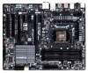
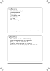
... (Part No. 12CR1-FPX582-0*R) - 6 - The box contents are for reference only and the actual items shall depend on the product package you obtain. Box Contents GA-Z68XP-UD3R motherboard Motherboard driver disk User's Manual Quick Installation Guide Four SATA cables I/O Shield One 2-Way SLI bridge connector The box contents above are subject to change without...
... (Part No. 12CR1-FPX582-0*R) - 6 - The box contents are for reference only and the actual items shall depend on the product package you obtain. Box Contents GA-Z68XP-UD3R motherboard Motherboard driver disk User's Manual Quick Installation Guide Four SATA cables I/O Shield One 2-Way SLI bridge connector The box contents above are subject to change without...
Manual
Page 7
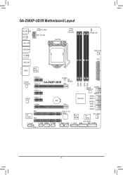
GA-Z68XP-UD3R Motherboard Layout KB_MS_USB OPTICAL USB_1394 SYS_FAN1 ATX_12V_2X4 LGA1155 CPU_FAN PHASE LED USB_HDMI R_USB30 USB_LAN AUDIO Etron EJ168 PWR_FAN ATX PCIEX1_1 B_BIOS Realtek RTL8111E CODEC VIA VT6308 PCIEX16 PCIEX1_2 PCIEX1_3 PCIEX8 PCI1 PCI2 DDR3_4 DDR3_2 DDR3_3 DDR3_1 GA-Z68XP-UD3R M_BIOS Marvell GSATA3_7 88SE9172 GSATA3_6 SATA3_1 Intel® Z68 SATA3_0 BAT SATA2_3 SATA2_2 SATA2_5 SATA2_4 PCIe to PCI Bridge Etron EJ168 iTE IT8728 SYS_FAN2 F_AUDIO CLR_CMOS F_1394 COMA F_USB3 F_USB2 F_USB1 F_USB30 TPM F_PANEL SPDIF_O - 7 -
GA-Z68XP-UD3R Motherboard Layout KB_MS_USB OPTICAL USB_1394 SYS_FAN1 ATX_12V_2X4 LGA1155 CPU_FAN PHASE LED USB_HDMI R_USB30 USB_LAN AUDIO Etron EJ168 PWR_FAN ATX PCIEX1_1 B_BIOS Realtek RTL8111E CODEC VIA VT6308 PCIEX16 PCIEX1_2 PCIEX1_3 PCIEX8 PCI1 PCI2 DDR3_4 DDR3_2 DDR3_3 DDR3_1 GA-Z68XP-UD3R M_BIOS Marvell GSATA3_7 88SE9172 GSATA3_6 SATA3_1 Intel® Z68 SATA3_0 BAT SATA2_3 SATA2_2 SATA2_5 SATA2_4 PCIe to PCI Bridge Etron EJ168 iTE IT8728 SYS_FAN2 F_AUDIO CLR_CMOS F_1394 COMA F_USB3 F_USB2 F_USB1 F_USB30 TPM F_PANEL SPDIF_O - 7 -
Manual
Page 8
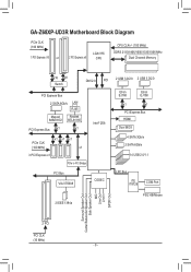
GA-Z68XP-UD3R Motherboard Block Diagram PCIe CLK (100 MHz) 1 PCI Express x16 or 2 PCI Express x8 LGA1155 CPU CPU CLK+/- (100 MHz) DDR3 2133/1866/1600/1333/1066 ...
GA-Z68XP-UD3R Motherboard Block Diagram PCIe CLK (100 MHz) 1 PCI Express x16 or 2 PCI Express x8 LGA1155 CPU CPU CLK+/- (100 MHz) DDR3 2133/1866/1600/1333/1066 ...
Manual
Page 9
... environment. •• Turning on the power, make sure they are connected tightly and securely. •• When handling the motherboard, avoid touching any installation steps or have a problem related to wear an electrostatic discharge (ESD) wrist strap when handling electronic com-... Chapter 1 Hardware Installation 1-1 Installation Precautions The motherboard contains numerous delicate electronic circuits and components which can lead to damage to system components as well as physical harm to the...
... environment. •• Turning on the power, make sure they are connected tightly and securely. •• When handling the motherboard, avoid touching any installation steps or have a problem related to wear an electrostatic discharge (ESD) wrist strap when handling electronic com-... Chapter 1 Hardware Installation 1-1 Installation Precautions The motherboard contains numerous delicate electronic circuits and components which can lead to damage to system components as well as physical harm to the...

Manual
Page 12
...;Š Support for Xpress Install ŠŠ Support for Xpress Recovery2 ŠŠ Support for EasyTune * Available functions in EasyTune may differ by motherboard model. ŠŠ Support for Dynamic Energy Saver™ 2 ŠŠ Support for Smart 6™ ŠŠ Support for Auto Green...138;Š Support for Microsoft® Windows 7/Vista/XP Form Factor ŠŠ ATX Form Factor; 30.5cm x 24.4cm * GIGABYTE reserves the right to make any changes to the integrated graphics port on the CPU/system cooler you install. Hardware ŠŠ System voltage...
...;Š Support for Xpress Install ŠŠ Support for Xpress Recovery2 ŠŠ Support for EasyTune * Available functions in EasyTune may differ by motherboard model. ŠŠ Support for Dynamic Energy Saver™ 2 ŠŠ Support for Smart 6™ ŠŠ Support for Auto Green...138;Š Support for Microsoft® Windows 7/Vista/XP Form Factor ŠŠ ATX Form Factor; 30.5cm x 24.4cm * GIGABYTE reserves the right to make any changes to the integrated graphics port on the CPU/system cooler you install. Hardware ŠŠ System voltage...

Manual
Page 13
... LGA1155 CPU Notch Notch Triangle Pin One Marking on the CPU. It is not installed, otherwise overheating and dam- Locate the alignment keys on the motherboard CPU socket and the notches on the CPU - 13 - The CPU cannot be set the frequency beyond hardware specifications since it does not meet the... standard requirements for the latest CPU support list.) •• Always turn on the computer if the CPU cooler is not recommended that the motherboard supports the CPU. (Go to GIGABYTE's website for the peripherals. age of the CPU.
... LGA1155 CPU Notch Notch Triangle Pin One Marking on the CPU. It is not installed, otherwise overheating and dam- Locate the alignment keys on the motherboard CPU socket and the notches on the CPU - 13 - The CPU cannot be set the frequency beyond hardware specifications since it does not meet the... standard requirements for the latest CPU support list.) •• Always turn on the computer if the CPU cooler is not recommended that the motherboard supports the CPU. (Go to GIGABYTE's website for the peripherals. age of the CPU.

Manual
Page 14
... the socket cover and use your index finger down and away from the power outlet to prevent damage to correctly install the CPU into the motherboard CPU socket. Hardware Installation - 14 - Step 2: Remove the CPU socket cover as well. When replacing the load plate, make sure to turn off the computer...
... the socket cover and use your index finger down and away from the power outlet to prevent damage to correctly install the CPU into the motherboard CPU socket. Hardware Installation - 14 - Step 2: Remove the CPU socket cover as well. When replacing the load plate, make sure to turn off the computer...

Manual
Page 15
..." when pushing down on the contrary, is complete. 1-3-2 Installing the CPU Cooler Follow the steps below to correctly install the CPU cooler on the motherboard. (The following procedure uses Intel® boxed cooler as the picture above shows, the installation is to install.) Step 3: Place the cooler atop the... CPU, aligning the four push pins through the pin holes on the motherboard. Push down each push pin. If the push pin is inserted as the example cooler.) Direction of the Arrow Sign on the Male Push...
..." when pushing down on the contrary, is complete. 1-3-2 Installing the CPU Cooler Follow the steps below to correctly install the CPU cooler on the motherboard. (The following procedure uses Intel® boxed cooler as the picture above shows, the installation is to install.) Step 3: Place the cooler atop the... CPU, aligning the four push pins through the pin holes on the motherboard. Push down each push pin. If the push pin is inserted as the example cooler.) Direction of the Arrow Sign on the Male Push...

Manual
Page 16
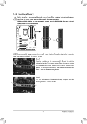
... Installation - 16 - A memory module can be used . (Go to insert the memory, switch the direction. 1-4-1 Dual Channel Memory Configuration This motherboard provides four DDR3 memory sockets and supports Dual Channel Technology. DS/SS DS/SS DDR3_2 DS/SS - DS/SS DDR3_3 - When enabling Dual Channel mode...four memory modules, it is installed, the BIOS will double the original memory bandwidth. The four DDR3 memory sockets are unable to GIGABYTE's website for the latest supported memory speeds and memory modules.) •• Always turn off the computer and unplug the power cord...
... Installation - 16 - A memory module can be used . (Go to insert the memory, switch the direction. 1-4-1 Dual Channel Memory Configuration This motherboard provides four DDR3 memory sockets and supports Dual Channel Technology. DS/SS DS/SS DDR3_2 DS/SS - DS/SS DDR3_3 - When enabling Dual Channel mode...four memory modules, it is installed, the BIOS will double the original memory bandwidth. The four DDR3 memory sockets are unable to GIGABYTE's website for the latest supported memory speeds and memory modules.) •• Always turn off the computer and unplug the power cord...
Manual
Page 17
..., make sure to turn off the computer and unplug the power cord from the power outlet to prevent damage to install DDR3 DIMMs on this motherboard. Hardware Installation DDR3 and DDR2 DIMMs are not compatible to each other or DDR DIMMs. Be sure to the memory module. Spread the retaining clips...
..., make sure to turn off the computer and unplug the power cord from the power outlet to prevent damage to install DDR3 DIMMs on this motherboard. Hardware Installation DDR3 and DDR2 DIMMs are not compatible to each other or DDR DIMMs. Be sure to the memory module. Spread the retaining clips...
Manual
Page 18
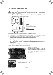
... the card and then pull the card straight up from the power outlet before you begin to install an expansion card: • Make sure the motherboard supports the expansion card.
... the card and then pull the card straight up from the power outlet before you begin to install an expansion card: • Make sure the motherboard supports the expansion card.
Manual
Page 19
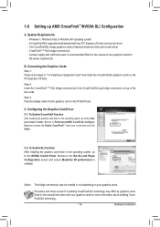
... and Physx Configuration screen and ensure Maximize 3D performance is enabled. (Note) The bridge connector(s) may differ by graphics cards. Hardware Installation A CrossFireX/SLI-supported motherboard with your graphics cards for the power requirement) B. Configuring the Graphics Card Driver C-1. To Enable SLI Function After installing the graphics card driver in the...
... and Physx Configuration screen and ensure Maximize 3D performance is enabled. (Note) The bridge connector(s) may differ by graphics cards. Hardware Installation A CrossFireX/SLI-supported motherboard with your graphics cards for the power requirement) B. Configuring the Graphics Card Driver C-1. To Enable SLI Function After installing the graphics card driver in the...

Manual
Page 21
... default speakers settings, the ~ audio jacks can be connected to the default Mic in a 7.1-channel audio configuration. Do not rock it straight out from the motherboard. •• When removing the cable, pull it side to side to prevent an electrical short inside the cable connector. - 21 - USB 3.0/2.0 Port The USB...
... default speakers settings, the ~ audio jacks can be connected to the default Mic in a 7.1-channel audio configuration. Do not rock it straight out from the motherboard. •• When removing the cable, pull it side to side to prevent an electrical short inside the cable connector. - 21 - USB 3.0/2.0 Port The USB...

Manual
Page 22
... 13) SPDIF_O 14) F_USB1/F_USB2/F_USB3 15) F_USB30 16) F_1394 17) CLR_CMOS 18) PHASE LED 19) TPM Read the following guidelines before turning on the motherboard. Hardware Installation - 22 -
... 13) SPDIF_O 14) F_USB1/F_USB2/F_USB3 15) F_USB30 16) F_1394 17) CLR_CMOS 18) PHASE LED 19) TPM Read the following guidelines before turning on the motherboard. Hardware Installation - 22 -

Manual
Page 23
... can supply enough stable power to all devices are properly installed. If the 12V power connector is turned off and all the components on the motherboard. Definition 1 GND (Only for 2x4-pin 12V) 2 GND (Only for 2x4-pin 12V) 3 GND 4 GND 5 +12V (Only for 2x4-pin 12V) 6 +12V (Only for 2x4...
... can supply enough stable power to all devices are properly installed. If the 12V power connector is turned off and all the components on the motherboard. Definition 1 GND (Only for 2x4-pin 12V) 2 GND (Only for 2x4-pin 12V) 3 GND 4 GND 5 +12V (Only for 2x4-pin 12V) 6 +12V (Only for 2x4...


