
Manual
Page 1
Enabling RAID mode in BIOS Setup: Turn on the hard disk will see shall depend on the motherboard you have installed the operating system before enabling the Smart Response Technology. 1. Enabling RAID mode in BIOS Setup 3. Set PCH SATA Control Mode under ... Storage Technology utility to enable the Intel Smart Response Technology • The Intel Smart Response Technology requires a computer system with an Intel Z68 Chipset-based motherboard and an Intel Core series CPU. • The operating system must be used for your data. 2. The actual BIOS Setup menu options you will...
Enabling RAID mode in BIOS Setup: Turn on the hard disk will see shall depend on the motherboard you have installed the operating system before enabling the Smart Response Technology. 1. Enabling RAID mode in BIOS Setup 3. Set PCH SATA Control Mode under ... Storage Technology utility to enable the Intel Smart Response Technology • The Intel Smart Response Technology requires a computer system with an Intel Z68 Chipset-based motherboard and an Intel Core series CPU. • The operating system must be used for your data. 2. The actual BIOS Setup menu options you will...

Manual
Page 2
... install the operating system. Make sure the Intel Rapid Storage Technology driver version is complete, use the "Xpress Install" function of the motherboard driver disk to install all motherboard drivers, including the Intel Rapid Storage Technology driver. Launching the Intel Rapid Storage Technology utility to enable the Intel Smart Response Technology: Step...
... install the operating system. Make sure the Intel Rapid Storage Technology driver version is complete, use the "Xpress Install" function of the motherboard driver disk to install all motherboard drivers, including the Intel Rapid Storage Technology driver. Launching the Intel Rapid Storage Technology utility to enable the Intel Smart Response Technology: Step...
Manual
Page 3
... copyright laws and is 1.0. Documentation Classifications In order to assist in this manual may be made by GIGABYTE without GIGABYTE's prior written permission. Check your motherboard looks like this manual may be reproduced, copied, translated, transmitted, or published in this manual are ...read the User's Manual. Changes to their respective owners. No part of GIGABYTE. Copyright © 2011 GIGA-BYTE TECHNOLOGY CO., LTD. All rights reserved. For example, "REV: 1.0" means the revision of the motherboard is the property of this : "REV: X.X." Example: For product-...
... copyright laws and is 1.0. Documentation Classifications In order to assist in this manual may be made by GIGABYTE without GIGABYTE's prior written permission. Check your motherboard looks like this manual may be reproduced, copied, translated, transmitted, or published in this manual are ...read the User's Manual. Changes to their respective owners. No part of GIGABYTE. Copyright © 2011 GIGA-BYTE TECHNOLOGY CO., LTD. All rights reserved. For example, "REV: 1.0" means the revision of the motherboard is the property of this : "REV: X.X." Example: For product-...
Manual
Page 4
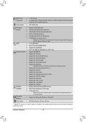
Table of Contents Box Contents...6 Optional Items...6 GA-Z68XP-UD3-iSSD/GA-Z68XP-UD3 Motherboard Layout 7 GA-Z68XP-UD3-iSSD/GA-Z68XP-UD3 Motherboard Block Diagram 8 Chapter 1 Hardware Installation 9 1-1 Installation Precautions 9 1-2 Product Specifications 10 1-3 Installing the CPU and CPU Cooler 13 1-3-1 Installing the CPU 13 1-3-2 Installing the CPU Cooler ...
Table of Contents Box Contents...6 Optional Items...6 GA-Z68XP-UD3-iSSD/GA-Z68XP-UD3 Motherboard Layout 7 GA-Z68XP-UD3-iSSD/GA-Z68XP-UD3 Motherboard Block Diagram 8 Chapter 1 Hardware Installation 9 1-1 Installation Precautions 9 1-2 Product Specifications 10 1-3 Installing the CPU and CPU Cooler 13 1-3-1 Installing the CPU 13 1-3-2 Installing the CPU Cooler ...

Manual
Page 6
Box Contents GA-Z68XP-UD3-iSSD or GA-Z68XP-UD3 motherboard Motherboard driver disk User's Manual Quick Installation Guide Four SATA cables I/O Shield One 2-Way SLI bridge connector SSD 20 GB j j Only for reference only and the ...actual items shall depend on the product package you obtain. The box contents above are subject to change without notice. The box contents are for GA-Z68XP-UD3...
Box Contents GA-Z68XP-UD3-iSSD or GA-Z68XP-UD3 motherboard Motherboard driver disk User's Manual Quick Installation Guide Four SATA cables I/O Shield One 2-Way SLI bridge connector SSD 20 GB j j Only for reference only and the ...actual items shall depend on the product package you obtain. The box contents above are subject to change without notice. The box contents are for GA-Z68XP-UD3...

Manual
Page 7
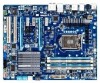
k Only for GA-Z68XP-UD3-iSSD. GA-Z68XP-UD3-iSSD/GA-Z68XP-UD3 Motherboard Layout KB_MS_USB OPTICAL USB_1394 SYS_FAN1 ATX_12V_2X4 LGA1155 CPU_FAN PHASE LED USB_HDMI R_USB30 USB_LAN PWR_FAN ATX AUDIO Etron EJ168 PCIEX1_1 mSATA+SSDj mSATAk DDR3_4 DDR3_2 DDR3_3 DDR3_1 Realtek RTL8111E PCIEX16 PCIEX1_2 CODEC PCIEX1_3 PCIEX8 PCI1 VIA VT6308 PCI2 GA-Z68XP-UD3-iSSD GA-Z68XP-UD3 BAT M_BIOS B_BIOS PCIe to PCI Bridge Intel®...
k Only for GA-Z68XP-UD3-iSSD. GA-Z68XP-UD3-iSSD/GA-Z68XP-UD3 Motherboard Layout KB_MS_USB OPTICAL USB_1394 SYS_FAN1 ATX_12V_2X4 LGA1155 CPU_FAN PHASE LED USB_HDMI R_USB30 USB_LAN PWR_FAN ATX AUDIO Etron EJ168 PCIEX1_1 mSATA+SSDj mSATAk DDR3_4 DDR3_2 DDR3_3 DDR3_1 Realtek RTL8111E PCIEX16 PCIEX1_2 CODEC PCIEX1_3 PCIEX8 PCI1 VIA VT6308 PCI2 GA-Z68XP-UD3-iSSD GA-Z68XP-UD3 BAT M_BIOS B_BIOS PCIe to PCI Bridge Intel®...

Manual
Page 8
GA-Z68XP-UD3-iSSD/GA-Z68XP-UD3 Motherboard Block Diagram PCIe CLK (100 MHz) 1 PCI Express x16 or 2 PCI Express x8 LGA1155 CPU CPU CLK+/- (100 MHz) DDR3 2133/1866/1600/1333/1066 ...
GA-Z68XP-UD3-iSSD/GA-Z68XP-UD3 Motherboard Block Diagram PCIe CLK (100 MHz) 1 PCI Express x16 or 2 PCI Express x8 LGA1155 CPU CPU CLK+/- (100 MHz) DDR3 2133/1866/1600/1333/1066 ...

Manual
Page 9
... as well as physical harm to the user. •• If you are connected tightly and securely. •• When handling the motherboard, avoid touching any installation steps or have it on top of an antistatic pad or within an electrostatic shielding container. •• Before...an ESD wrist strap, keep your hands dry and first touch a metal object to eliminate static electricity. •• Prior to installing the motherboard, please have a problem related to the local voltage standard. •• Before using the product, please verify that all cables and power ...
... as well as physical harm to the user. •• If you are connected tightly and securely. •• When handling the motherboard, avoid touching any installation steps or have it on top of an antistatic pad or within an electrostatic shielding container. •• Before...an ESD wrist strap, keep your hands dry and first touch a metal object to eliminate static electricity. •• Prior to installing the motherboard, please have a problem related to the local voltage standard. •• Before using the product, please verify that all cables and power ...
Manual
Page 12
...Center ŠŠ Support for Xpress Install ŠŠ Support for Xpress Recovery2 ŠŠ Support for EasyTune * Available functions in EasyTune may differ by motherboard model. ŠŠ Support for Dynamic Energy Saver™ 2 ŠŠ Support for Smart 6™ ŠŠ Support for Auto Green Š...for TouchBIOS ŠŠ Support for Microsoft® Windows 7/Vista/XP Form Factor ŠŠ ATX Form Factor; 30.5cm x 24.4cm * GIGABYTE reserves the right to make any changes to the integrated graphics port on the CPU/system cooler you install.
...Center ŠŠ Support for Xpress Install ŠŠ Support for Xpress Recovery2 ŠŠ Support for EasyTune * Available functions in EasyTune may differ by motherboard model. ŠŠ Support for Dynamic Energy Saver™ 2 ŠŠ Support for Smart 6™ ŠŠ Support for Auto Green Š...for TouchBIOS ŠŠ Support for Microsoft® Windows 7/Vista/XP Form Factor ŠŠ ATX Form Factor; 30.5cm x 24.4cm * GIGABYTE reserves the right to make any changes to the integrated graphics port on the CPU/system cooler you install.

Manual
Page 13
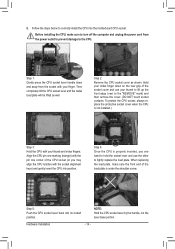
... the CPU Socket LGA1155 CPU Notch Notch Triangle Pin One Marking on the computer if the CPU cooler is not recommended that the motherboard supports the CPU. (Go to GIGABYTE's website for the peripherals. Hardware Installation The CPU cannot be set the frequency beyond hardware specifications since it does not meet the...
... the CPU Socket LGA1155 CPU Notch Notch Triangle Pin One Marking on the computer if the CPU cooler is not recommended that the motherboard supports the CPU. (Go to GIGABYTE's website for the peripherals. Hardware Installation The CPU cannot be set the frequency beyond hardware specifications since it does not meet the...
Manual
Page 14
... to lift up the front edge (next to lightly replace the load plate. Hardware Installation - 14 - Step 5: Push the CPU socket lever back into the motherboard CPU socket. B. Follow the steps below to the CPU. Hold your finger.
... to lift up the front edge (next to lightly replace the load plate. Hardware Installation - 14 - Step 5: Push the CPU socket lever back into the motherboard CPU socket. B. Follow the steps below to the CPU. Hold your finger.

Manual
Page 15
...the CPU cooler may adhere to install.) Step 3: Place the cooler atop the CPU, aligning the four push pins through the pin holes on the motherboard. Step 4: You should hear a "click" when pushing down on the push pins diagonally. Hardware Installation Step 2: Before installing the cooler, note... check the back of the CPU cooler to the CPU fan header (CPU_FAN) on the motherboard. 1-3-2 Installing the CPU Cooler Follow the steps below to correctly install the CPU cooler on the motherboard. (The following procedure uses Intel® boxed cooler as the picture above shows, the ...
...the CPU cooler may adhere to install.) Step 3: Place the cooler atop the CPU, aligning the four push pins through the pin holes on the motherboard. Step 4: You should hear a "click" when pushing down on the push pins diagonally. Hardware Installation Step 2: Before installing the cooler, note... check the back of the CPU cooler to the CPU fan header (CPU_FAN) on the motherboard. 1-3-2 Installing the CPU Cooler Follow the steps below to correctly install the CPU cooler on the motherboard. (The following procedure uses Intel® boxed cooler as the picture above shows, the ...
Manual
Page 16
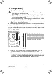
...capacity of the same capacity, brand, speed, and chips be enabled if only one direction. Dual Channel mode cannot be used . (Go to GIGABYTE's website for the latest supported memory speeds and memory modules.) •• Always turn off the computer and unplug the power cord from the ...used and installed in the same colored DDR3 sockets. If you install them in the DDR3_1 and DDR3_2 sockets. It is recommended that the motherboard supports the memory. For optimum performance, when enabling Dual Channel mode with two or four memory modules, it is recommended that you are ...
...capacity of the same capacity, brand, speed, and chips be enabled if only one direction. Dual Channel mode cannot be used . (Go to GIGABYTE's website for the latest supported memory speeds and memory modules.) •• Always turn off the computer and unplug the power cord from the ...used and installed in the same colored DDR3 sockets. If you install them in the DDR3_1 and DDR3_2 sockets. It is recommended that the motherboard supports the memory. For optimum performance, when enabling Dual Channel mode with two or four memory modules, it is recommended that you are ...

Manual
Page 17
..., make sure to turn off the computer and unplug the power cord from the power outlet to prevent damage to install DDR3 DIMMs on this motherboard.
..., make sure to turn off the computer and unplug the power cord from the power outlet to prevent damage to install DDR3 DIMMs on this motherboard.
Manual
Page 18
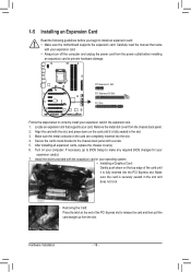
... turn off the computer and unplug the power cord from the power outlet before you begin to install an expansion card: • Make sure the motherboard supports the expansion card. Hardware Installation - 18 - Carefully read the manual that supports your computer.
... turn off the computer and unplug the power cord from the power outlet before you begin to install an expansion card: • Make sure the motherboard supports the expansion card. Hardware Installation - 18 - Carefully read the manual that supports your computer.

Manual
Page 19
...\AMD CrossFireX Configurations and ensure the Enable CrossFireX™ check box is enabled. (Note) The bridge connector(s) may differ by graphics cards. A CrossFireX/SLI-supported motherboard with your graphics cards. Step 3: Plug the display cable into the graphics card on the PCI Express x16 slots. To Enable CrossFireX Function After installing...
...\AMD CrossFireX Configurations and ensure the Enable CrossFireX™ check box is enabled. (Note) The bridge connector(s) may differ by graphics cards. A CrossFireX/SLI-supported motherboard with your graphics cards. Step 3: Plug the display cable into the graphics card on the PCI Express x16 slots. To Enable CrossFireX Function After installing...
Manual
Page 20
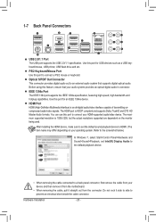
... and DTS HD Master Audio formats. Hardware Installation - 20 - Use this port for an IEEE 1394a device. Do not rock it straight out from the motherboard. •• When removing the cable, pull it side to side to HDMI. (The item name may differ depending on the monitor being used. 1-7 Back...
... and DTS HD Master Audio formats. Hardware Installation - 20 - Use this port for an IEEE 1394a device. Do not rock it straight out from the motherboard. •• When removing the cable, pull it side to side to HDMI. (The item name may differ depending on the monitor being used. 1-7 Back...

Manual
Page 22
... 14) F_AUDIO 15) SPDIF_O 16) F_USB1/F_USB2/F_USB3 17) F_USB30 18) F_1394 19) PHASE LED 20) TPM Read the following guidelines before turning on the motherboard. Hardware Installation - 22 -
... 14) F_AUDIO 15) SPDIF_O 16) F_USB1/F_USB2/F_USB3 17) F_USB30 18) F_1394 19) PHASE LED 20) TPM Read the following guidelines before turning on the motherboard. Hardware Installation - 22 -

Manual
Page 23
...-pin ATX) - 23 - Connect the power supply cable to the CPU. If the 12V power connector is turned off and all the components on the motherboard. Hardware Installation Before connecting the power connector, first make sure the power supply is not connected, the computer will not start. 1/2) ATX_12V_2X4/ATX (2x2 12V...
...-pin ATX) - 23 - Connect the power supply cable to the CPU. If the 12V power connector is turned off and all the components on the motherboard. Hardware Installation Before connecting the power connector, first make sure the power supply is not connected, the computer will not start. 1/2) ATX_12V_2X4/ATX (2x2 12V...

Manual
Page 24
...battery, note the orientation of the positive side (+) and the negative side (-) of a CPU fan with local environmental regulations. The motherboard supports CPU fan speed control, which requires the use of the battery (the positive side should face up). •• Used ... battery: 111 Turn off your computer and unplug the power cord. 222 Gently remove the battery from overheating. 3/4/5) CPU_FAN/SYS_FAN1/SYS_FAN2/PWR_FAN (Fan Headers) The motherboard has a 4-pin CPU fan header (CPU_FAN), a 4-pin (SYS_FAN2) and a 3-pin (SYS_FAN1) system fan headers, and a 3-pin power fan header (...
...battery, note the orientation of the positive side (+) and the negative side (-) of a CPU fan with local environmental regulations. The motherboard supports CPU fan speed control, which requires the use of the battery (the positive side should face up). •• Used ... battery: 111 Turn off your computer and unplug the power cord. 222 Gently remove the battery from overheating. 3/4/5) CPU_FAN/SYS_FAN1/SYS_FAN2/PWR_FAN (Fan Headers) The motherboard has a 4-pin CPU fan header (CPU_FAN), a 4-pin (SYS_FAN2) and a 3-pin (SYS_FAN1) system fan headers, and a 3-pin power fan header (...


