
Manual
Page 1
...utility to enable the Intel Smart Response Technology • The Intel Smart Response Technology requires a computer system with an Intel Z68 Chipset-based motherboard and an Intel Core series CPU. • The operating system must be used for your data. 2. Then save changes and exit BIOS ... ESC: Exit F1: General Help F7: Optimized Defaults The BIOS Setup menus described here may differ from the exact settings for storing your motherboard. Installing the operating system and drivers to make it work as a cache of the hard disk. Installing a conventional SATA hard disk and...
...utility to enable the Intel Smart Response Technology • The Intel Smart Response Technology requires a computer system with an Intel Z68 Chipset-based motherboard and an Intel Core series CPU. • The operating system must be used for your data. 2. Then save changes and exit BIOS ... ESC: Exit F1: General Help F7: Optimized Defaults The BIOS Setup menus described here may differ from the exact settings for storing your motherboard. Installing the operating system and drivers to make it work as a cache of the hard disk. Installing a conventional SATA hard disk and...

Manual
Page 2
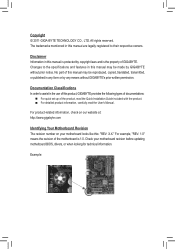
Make sure the Intel Rapid Storage Technology driver version is complete, use the "Xpress Install" function of the motherboard driver disk to open the Intel Rapid Storage Technology utility. - 2 - Launching the Intel Rapid Storage Technology utility to enable the Intel Smart Response Technology... or above and restarting your system, find the IRST icon in the notification area and double-click it to install all motherboard drivers, including the Intel Rapid Storage Technology driver. Installing the operating system and drivers to the SATA disk: After setting the BIOS, you ...
Make sure the Intel Rapid Storage Technology driver version is complete, use the "Xpress Install" function of the motherboard driver disk to open the Intel Rapid Storage Technology utility. - 2 - Launching the Intel Rapid Storage Technology utility to enable the Intel Smart Response Technology... or above and restarting your system, find the IRST icon in the notification area and double-click it to install all motherboard drivers, including the Intel Rapid Storage Technology driver. Installing the operating system and drivers to the SATA disk: After setting the BIOS, you ...
Manual
Page 3
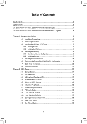
...Changes to the specifications and features in any form or by GIGABYTE without GIGABYTE's prior written permission. For example, "REV: 1.0" means the revision of the motherboard is the property of GIGABYTE. Check your motherboard looks like this manual may be reproduced, copied, translated, ... Manual. For product-related information, check on our website at: http://www.gigabyte.com Identifying Your Motherboard Revision The revision number on your motherboard revision before updating motherboard BIOS, drivers, or when looking for technical information. All rights reserved. Copyright...
...Changes to the specifications and features in any form or by GIGABYTE without GIGABYTE's prior written permission. For example, "REV: 1.0" means the revision of the motherboard is the property of GIGABYTE. Check your motherboard looks like this manual may be reproduced, copied, translated, ... Manual. For product-related information, check on our website at: http://www.gigabyte.com Identifying Your Motherboard Revision The revision number on your motherboard revision before updating motherboard BIOS, drivers, or when looking for technical information. All rights reserved. Copyright...
Manual
Page 4
Table of Contents Box Contents...6 Optional Items...6 GA-Z68XP-UD3-iSSD/GA-Z68XP-UD3 Motherboard Layout 7 GA-Z68XP-UD3-iSSD/GA-Z68XP-UD3 Motherboard Block Diagram 8 Chapter 1 Hardware Installation 9 1-1 Installation Precautions 9 1-2 Product Specifications 10 1-3 Installing the CPU and CPU Cooler 13 1-3-1 Installing the CPU 13 1-3-2 Installing the CPU Cooler ...
Table of Contents Box Contents...6 Optional Items...6 GA-Z68XP-UD3-iSSD/GA-Z68XP-UD3 Motherboard Layout 7 GA-Z68XP-UD3-iSSD/GA-Z68XP-UD3 Motherboard Block Diagram 8 Chapter 1 Hardware Installation 9 1-1 Installation Precautions 9 1-2 Product Specifications 10 1-3 Installing the CPU and CPU Cooler 13 1-3-1 Installing the CPU 13 1-3-2 Installing the CPU Cooler ...

Manual
Page 6
The box contents are for GA-Z68XP-UD3-iSSD. Box Contents GA-Z68XP-UD3-iSSD or GA-Z68XP-UD3 motherboard Motherboard driver disk User's Manual Quick Installation Guide Four SATA cables I/O Shield One 2-Way SLI bridge connector SSD 20 GB j j Only for reference only and the ...
The box contents are for GA-Z68XP-UD3-iSSD. Box Contents GA-Z68XP-UD3-iSSD or GA-Z68XP-UD3 motherboard Motherboard driver disk User's Manual Quick Installation Guide Four SATA cables I/O Shield One 2-Way SLI bridge connector SSD 20 GB j j Only for reference only and the ...

Manual
Page 7
k Only for GA-Z68XP-UD3-iSSD. GA-Z68XP-UD3-iSSD/GA-Z68XP-UD3 Motherboard Layout KB_MS_USB OPTICAL USB_1394 SYS_FAN1 ATX_12V_2X4 LGA1155 CPU_FAN PHASE LED USB_HDMI R_USB30 USB_LAN PWR_FAN ATX AUDIO Etron EJ168 PCIEX1_1 mSATA+SSDj mSATAk DDR3_4 DDR3_2 DDR3_3 DDR3_1 Realtek RTL8111E PCIEX16 PCIEX1_2 CODEC PCIEX1_3 PCIEX8 PCI1 VIA VT6308 PCI2 GA-Z68XP-UD3-iSSD GA-Z68XP-UD3 BAT M_BIOS B_BIOS PCIe to PCI Bridge Intel® Z68 Marvell GSATA3_7...
k Only for GA-Z68XP-UD3-iSSD. GA-Z68XP-UD3-iSSD/GA-Z68XP-UD3 Motherboard Layout KB_MS_USB OPTICAL USB_1394 SYS_FAN1 ATX_12V_2X4 LGA1155 CPU_FAN PHASE LED USB_HDMI R_USB30 USB_LAN PWR_FAN ATX AUDIO Etron EJ168 PCIEX1_1 mSATA+SSDj mSATAk DDR3_4 DDR3_2 DDR3_3 DDR3_1 Realtek RTL8111E PCIEX16 PCIEX1_2 CODEC PCIEX1_3 PCIEX8 PCI1 VIA VT6308 PCI2 GA-Z68XP-UD3-iSSD GA-Z68XP-UD3 BAT M_BIOS B_BIOS PCIe to PCI Bridge Intel® Z68 Marvell GSATA3_7...

Manual
Page 8
GA-Z68XP-UD3-iSSD/GA-Z68XP-UD3 Motherboard Block Diagram PCIe CLK (100 MHz) 1 PCI Express x16 or 2 PCI Express x8 LGA1155 CPU CPU CLK+/- (100 MHz) DDR3 2133/1866/1600/1333/1066 ...
GA-Z68XP-UD3-iSSD/GA-Z68XP-UD3 Motherboard Block Diagram PCIe CLK (100 MHz) 1 PCI Express x16 or 2 PCI Express x8 LGA1155 CPU CPU CLK+/- (100 MHz) DDR3 2133/1866/1600/1333/1066 ...

Manual
Page 9
... screws to come in a high-temperature environment. •• Turning on the computer power during the installation process can become damaged as a motherboard, CPU or memory. If you are uncertain about any metal leads or connectors. •• It is best to wear an electrostatic discharge ...for warranty validation. •• Always remove the AC power by your hardware components are connected. •• To prevent damage to the motherboard, do not have an ESD wrist strap, keep your hands dry and first touch a metal object to eliminate static electricity. ••...
... screws to come in a high-temperature environment. •• Turning on the computer power during the installation process can become damaged as a motherboard, CPU or memory. If you are uncertain about any metal leads or connectors. •• It is best to wear an electrostatic discharge ...for warranty validation. •• Always remove the AC power by your hardware components are connected. •• To prevent damage to the motherboard, do not have an ESD wrist strap, keep your hands dry and first touch a metal object to eliminate static electricity. ••...
Manual
Page 12
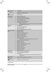
... ŠŠ Support for Xpress Install ŠŠ Support for Xpress Recovery2 ŠŠ Support for EasyTune * Available functions in EasyTune may differ by motherboard model. ŠŠ Support for Dynamic Energy Saver™ 2 ŠŠ Support for Smart 6™ ŠŠ Support for Auto Green Š...for TouchBIOS ŠŠ Support for Microsoft® Windows 7/Vista/XP Form Factor ŠŠ ATX Form Factor; 30.5cm x 24.4cm * GIGABYTE reserves the right to make any changes to the integrated graphics port on the CPU/system cooler you install.
... ŠŠ Support for Xpress Install ŠŠ Support for Xpress Recovery2 ŠŠ Support for EasyTune * Available functions in EasyTune may differ by motherboard model. ŠŠ Support for Dynamic Energy Saver™ 2 ŠŠ Support for Smart 6™ ŠŠ Support for Auto Green Š...for TouchBIOS ŠŠ Support for Microsoft® Windows 7/Vista/XP Form Factor ŠŠ ATX Form Factor; 30.5cm x 24.4cm * GIGABYTE reserves the right to make any changes to the integrated graphics port on the CPU/system cooler you install.

Manual
Page 13
It is not recommended that the motherboard supports the CPU. (Go to GIGABYTE's website for the peripherals. LGA1155 CPU Socket Alignment Key Alignment Key Pin One Corner of the CPU Socket LGA1155 CPU Notch Notch Triangle Pin One ... the CPU A. If you may occur. •• Set the CPU host frequency in accordance with the CPU specifications. Locate the alignment keys on the motherboard CPU socket and the notches on the CPU - 13 - age of the CPU may locate the notches on both sides of the CPU and alignment...
It is not recommended that the motherboard supports the CPU. (Go to GIGABYTE's website for the peripherals. LGA1155 CPU Socket Alignment Key Alignment Key Pin One Corner of the CPU Socket LGA1155 CPU Notch Notch Triangle Pin One ... the CPU A. If you may occur. •• Set the CPU host frequency in accordance with the CPU specifications. Locate the alignment keys on the motherboard CPU socket and the notches on the CPU - 13 - age of the CPU may locate the notches on both sides of the CPU and alignment...
Manual
Page 14
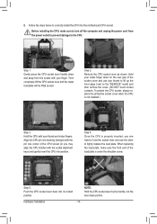
... your finger. NOTE: Hold the CPU socket lever by the handle, not the lever base portion. Step 5: Push the CPU socket lever back into the motherboard CPU socket. Follow the steps below to lightly replace the load plate. Step 2: Remove the CPU socket cover as well. To protect the CPU socket...
... your finger. NOTE: Hold the CPU socket lever by the handle, not the lever base portion. Step 5: Push the CPU socket lever back into the motherboard CPU socket. Follow the steps below to lightly replace the load plate. Step 2: Remove the CPU socket cover as well. To protect the CPU socket...

Manual
Page 15
... joined closely. (Refer to the CPU fan header (CPU_FAN) on installing the cooler.) Step 5: After the installation, check the back of the motherboard. Hardware Installation Push down each push pin. Step 6: Finally, attach the power connector of the CPU cooler to your CPU cooler installation manual for... Female Push Pin Step 1: Apply an even and thin layer of thermal grease on the surface of arrow is to remove the cooler, on the motherboard. 1-3-2 Installing the CPU Cooler Follow the steps below to the CPU. Step 4: You should hear a "click" when pushing down on the male...
... joined closely. (Refer to the CPU fan header (CPU_FAN) on installing the cooler.) Step 5: After the installation, check the back of the motherboard. Hardware Installation Push down each push pin. Step 6: Finally, attach the power connector of the CPU cooler to your CPU cooler installation manual for... Female Push Pin Step 1: Apply an even and thin layer of thermal grease on the surface of arrow is to remove the cooler, on the motherboard. 1-3-2 Installing the CPU Cooler Follow the steps below to the CPU. Step 4: You should hear a "click" when pushing down on the male...
Manual
Page 16
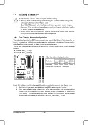
...Double-Sided, "- -"=No Memory) DDR3_4 DDR3_2 DDR3_3 DDR3_1 Due to insert the memory, switch the direction. 1-4-1 Dual Channel Memory Configuration This motherboard provides four DDR3 memory sockets and supports Dual Channel Technology. Dual Channel mode cannot be enabled if only one direction. When enabling Dual Channel ...mode with two memory modules, we recommend that memory of the same capacity, brand, speed, and chips be used . (Go to GIGABYTE's website for the latest supported memory speeds and memory modules.) •• Always turn off the computer and unplug the power cord from...
...Double-Sided, "- -"=No Memory) DDR3_4 DDR3_2 DDR3_3 DDR3_1 Due to insert the memory, switch the direction. 1-4-1 Dual Channel Memory Configuration This motherboard provides four DDR3 memory sockets and supports Dual Channel Technology. Dual Channel mode cannot be enabled if only one direction. When enabling Dual Channel ...mode with two memory modules, we recommend that memory of the same capacity, brand, speed, and chips be used . (Go to GIGABYTE's website for the latest supported memory speeds and memory modules.) •• Always turn off the computer and unplug the power cord from...

Manual
Page 17
..., make sure to turn off the computer and unplug the power cord from the power outlet to prevent damage to install DDR3 DIMMs on this motherboard. DDR3 and DDR2 DIMMs are not compatible to each other or DDR DIMMs. Be sure to the memory module. Follow the steps below to correctly...
..., make sure to turn off the computer and unplug the power cord from the power outlet to prevent damage to install DDR3 DIMMs on this motherboard. DDR3 and DDR2 DIMMs are not compatible to each other or DDR DIMMs. Be sure to the memory module. Follow the steps below to correctly...
Manual
Page 18
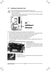
PCI Express x1 Slot PCI Express x16 Slot PCI Slot Follow the steps below to install an expansion card: • Make sure the motherboard supports the expansion card. Make sure the card is securely seated in the slot and does not rock. • Removing the Card: Press the latch ...
PCI Express x1 Slot PCI Express x16 Slot PCI Slot Follow the steps below to install an expansion card: • Make sure the motherboard supports the expansion card. Make sure the card is securely seated in the slot and does not rock. • Removing the Card: Press the latch ...

Manual
Page 19
A CrossFireX/SLI-supported motherboard with your graphics cards for more information about enabling CrossFireX/SLI technology. - 19 - Step 2: Insert the CrossFireX (Note)/SLI bridge connector(s) in the operating system, ...
A CrossFireX/SLI-supported motherboard with your graphics cards for more information about enabling CrossFireX/SLI technology. - 19 - Step 2: Insert the CrossFireX (Note)/SLI bridge connector(s) in the operating system, ...
Manual
Page 20
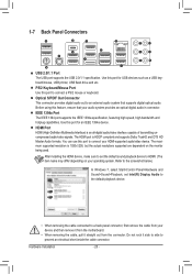
... digital optical audio. The maximum supported resolution is 1920x1200, but the actual resolutions supported are dependent on your device and then remove it from the motherboard. •• When removing the cable, pull it side to side to HDMI. (The item name may differ depending on the monitor being used. Refer...
... digital optical audio. The maximum supported resolution is 1920x1200, but the actual resolutions supported are dependent on your device and then remove it from the motherboard. •• When removing the cable, pull it side to side to HDMI. (The item name may differ depending on the monitor being used. Refer...

Manual
Page 22
... sure your devices are compliant with the connectors you wish to connect. •• Before installing the devices, be sure to the connector on the motherboard. Hardware Installation - 22 -
... sure your devices are compliant with the connectors you wish to connect. •• Before installing the devices, be sure to the connector on the motherboard. Hardware Installation - 22 -

Manual
Page 23
... the power supply is not connected, the computer will not start. If the 12V power connector is turned off and all the components on the motherboard. 1/2) ATX_12V_2X4/ATX (2x2 12V Power Connector and 2x12 Main Power Connector) With the use of the power connector, the power supply can supply enough stable...
... the power supply is not connected, the computer will not start. If the 12V power connector is turned off and all the components on the motherboard. 1/2) ATX_12V_2X4/ATX (2x2 12V Power Connector and 2x12 Main Power Connector) With the use of the power connector, the power supply can supply enough stable...

Manual
Page 24
... configurations, date, and time information) in damage to replace the battery by removing the battery: 111 Turn off . The motherboard supports CPU fan speed control, which requires the use a metal object like a screwdriver to touch the positive and negative terminals... 222 Gently remove the battery from overheating. Replace the battery when the battery voltage drops to prevent your - 3/4/5) CPU_FAN/SYS_FAN1/SYS_FAN2/PWR_FAN (Fan Headers) The motherboard has a 4-pin CPU fan header (CPU_FAN), a 4-pin (SYS_FAN2) and a 3-pin (SYS_FAN1) system fan headers, and a 3-pin power fan header ...
... configurations, date, and time information) in damage to replace the battery by removing the battery: 111 Turn off . The motherboard supports CPU fan speed control, which requires the use a metal object like a screwdriver to touch the positive and negative terminals... 222 Gently remove the battery from overheating. Replace the battery when the battery voltage drops to prevent your - 3/4/5) CPU_FAN/SYS_FAN1/SYS_FAN2/PWR_FAN (Fan Headers) The motherboard has a 4-pin CPU fan header (CPU_FAN), a 4-pin (SYS_FAN2) and a 3-pin (SYS_FAN1) system fan headers, and a 3-pin power fan header ...


