
Manual
Page 1
...up the hard disk before configuring the Smart Response Technology, all original data on the hard disk will see shall depend on your motherboard. Installing a conventional SATA hard disk and a solid-state drive (SSD): Besides the conventional SATA disk, you use an SSD larger than... to enable the Intel Smart Response Technology • The Intel Smart Response Technology requires a computer system with an Intel Z68 Chipset-based motherboard and an Intel Core series CPU. • The operating system must be lost once you have installed the operating system before enabling the...
...up the hard disk before configuring the Smart Response Technology, all original data on the hard disk will see shall depend on your motherboard. Installing a conventional SATA hard disk and a solid-state drive (SSD): Besides the conventional SATA disk, you use an SSD larger than... to enable the Intel Smart Response Technology • The Intel Smart Response Technology requires a computer system with an Intel Z68 Chipset-based motherboard and an Intel Core series CPU. • The operating system must be lost once you have installed the operating system before enabling the...

Manual
Page 2
Make sure the Intel Rapid Storage Technology driver version is complete, use the "Xpress Install" function of the motherboard driver disk to install all motherboard drivers, including the Intel Rapid Storage Technology driver. Installing the operating system and drivers to the SATA disk: After setting the BIOS, you can begin ...
Make sure the Intel Rapid Storage Technology driver version is complete, use the "Xpress Install" function of the motherboard driver disk to install all motherboard drivers, including the Intel Rapid Storage Technology driver. Installing the operating system and drivers to the SATA disk: After setting the BIOS, you can begin ...
Manual
Page 2
Motherboard GA-Z68M-D2H Jun. 10, 2011 Motherboard GA-Z68M-D2H Jun. 10, 2011
Motherboard GA-Z68M-D2H Jun. 10, 2011 Motherboard GA-Z68M-D2H Jun. 10, 2011
Manual
Page 3
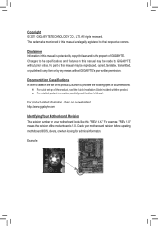
... in any form or by GIGABYTE without GIGABYTE's prior written permission. No part of GIGABYTE. For product-related information, check on our website at: http://www.gigabyte.com Identifying Your Motherboard Revision The revision number on your motherboard revision before updating motherboard BIOS, drivers, or when ...manual may be reproduced, copied, translated, transmitted, or published in this product, GIGABYTE provides the following types of documentations: For quick set-up of the motherboard is the property of this manual may be made by any means without prior notice...
... in any form or by GIGABYTE without GIGABYTE's prior written permission. No part of GIGABYTE. For product-related information, check on our website at: http://www.gigabyte.com Identifying Your Motherboard Revision The revision number on your motherboard revision before updating motherboard BIOS, drivers, or when ...manual may be reproduced, copied, translated, transmitted, or published in this product, GIGABYTE provides the following types of documentations: For quick set-up of the motherboard is the property of this manual may be made by any means without prior notice...
Manual
Page 4
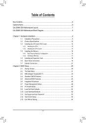
Table of Contents Box Contents...6 Optional Items...6 GA-Z68M-D2H Motherboard Layout 7 GA-Z68M-D2H Motherboard Block Diagram 8 Chapter 1 Hardware Installation 9 1-1 Installation Precautions 9 1-2 Product Specifications 10 1-3 Installing the CPU and CPU Cooler 13 1-3-1 Installing the CPU 13 1-3-2 Installing the CPU Cooler ...
Table of Contents Box Contents...6 Optional Items...6 GA-Z68M-D2H Motherboard Layout 7 GA-Z68M-D2H Motherboard Block Diagram 8 Chapter 1 Hardware Installation 9 1-1 Installation Precautions 9 1-2 Product Specifications 10 1-3 Installing the CPU and CPU Cooler 13 1-3-1 Installing the CPU 13 1-3-2 Installing the CPU Cooler ...
Manual
Page 6
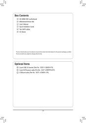
The box contents are for reference only and the actual items shall depend on the product package you obtain. Optional Items 2-port USB 2.0 bracket (Part No. 12CR1-1UB030-5*R) 2-port SATA power cable (Part No. 12CF1-2SERPW-0*R) COM port cable (Part No. 12CF1-1CM001-3*R) - 6 - Box Contents GA-Z68M-D2H motherboard Motherboard driver disk User's Manual Quick Installation Guide Two SATA cables I/O Shield The box contents above are subject to change without notice.
The box contents are for reference only and the actual items shall depend on the product package you obtain. Optional Items 2-port USB 2.0 bracket (Part No. 12CR1-1UB030-5*R) 2-port SATA power cable (Part No. 12CF1-2SERPW-0*R) COM port cable (Part No. 12CF1-1CM001-3*R) - 6 - Box Contents GA-Z68M-D2H motherboard Motherboard driver disk User's Manual Quick Installation Guide Two SATA cables I/O Shield The box contents above are subject to change without notice.
Manual
Page 7
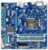
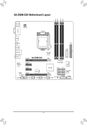
GA-Z68M-D2H Motherboard Layout DDR3_4 DDR3_2 DDR3_3 DDR3_1 KB_USB ATX_12V LGA1155 VGA_DVI HDMI OPTICAL R_USB USB_LAN CPU_FAN ATX TPM AUDIO Realtek RTL8111E PCIEX16 GA-Z68M-D2H PCIEX1_1 B_BIOS M_BIOS iTE IT8728 PCIEX1_2 CODEC PCIEX4 SPDIF_O F_AUDIO F_USB4 BAT F_USB3 F_USB2 Intel® Z68 SATA3_0 SATA3_1 SATA2_2 SATA2_3 SYS_FAN SATA2_4 SATA2_5 F_PANEL COM CLR_CMOS F_USB1 - 7 -
GA-Z68M-D2H Motherboard Layout DDR3_4 DDR3_2 DDR3_3 DDR3_1 KB_USB ATX_12V LGA1155 VGA_DVI HDMI OPTICAL R_USB USB_LAN CPU_FAN ATX TPM AUDIO Realtek RTL8111E PCIEX16 GA-Z68M-D2H PCIEX1_1 B_BIOS M_BIOS iTE IT8728 PCIEX1_2 CODEC PCIEX4 SPDIF_O F_AUDIO F_USB4 BAT F_USB3 F_USB2 Intel® Z68 SATA3_0 SATA3_1 SATA2_2 SATA2_3 SYS_FAN SATA2_4 SATA2_5 F_PANEL COM CLR_CMOS F_USB1 - 7 -
Manual
Page 8
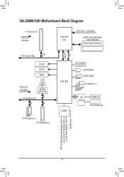
GA-Z68M-D2H Motherboard Block Diagram 1 PCI Express x16 PCIe CLK (100 MHz) LGA1155 CPU CPU CLK+/- (100 MHz) DDR3 2133/1866/1600/ 1333/1066 MHz Dual Channel Memory DMI 2.0 FDI PCI Express Bus x16 D-Sub DVI-D HDMI PCIe CLK (100 MHz) LAN RJ45 Realtek RTL8111E x1 PCI Express Bus x1 x4 2 PCI Express x1 1 PCI Express x4 Intel® Z68 Dual BIOS 2 SATA 6Gb/s 4 SATA 3Gb/s 14 USB 2.0/1.1 CODEC LPC Bus iTE IT8728 COM Port PS/2 KB/Mouse MIC (Center/Subwoofer Speaker Out) Line Out (Front Speaker Out) Line In (Rear Speaker Out) S/PDIF Out - 8 -
GA-Z68M-D2H Motherboard Block Diagram 1 PCI Express x16 PCIe CLK (100 MHz) LGA1155 CPU CPU CLK+/- (100 MHz) DDR3 2133/1866/1600/ 1333/1066 MHz Dual Channel Memory DMI 2.0 FDI PCI Express Bus x16 D-Sub DVI-D HDMI PCIe CLK (100 MHz) LAN RJ45 Realtek RTL8111E x1 PCI Express Bus x1 x4 2 PCI Express x1 1 PCI Express x4 Intel® Z68 Dual BIOS 2 SATA 6Gb/s 4 SATA 3Gb/s 14 USB 2.0/1.1 CODEC LPC Bus iTE IT8728 COM Port PS/2 KB/Mouse MIC (Center/Subwoofer Speaker Out) Line Out (Front Speaker Out) Line In (Rear Speaker Out) S/PDIF Out - 8 -
Manual
Page 9
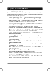
... validation. •• Always remove the AC power by your dealer. Hardware Installation Chapter 1 Hardware Installation 1-1 Installation Precautions The motherboard contains numerous delicate electronic circuits and components which can lead to damage to system components as well as physical harm to the user.... environment. •• Turning on the power, make sure they are connected tightly and securely. •• When handling the motherboard, avoid touching any metal leads or connectors. •• It is best to wear an electrostatic discharge (ESD) wrist strap when handling...
... validation. •• Always remove the AC power by your dealer. Hardware Installation Chapter 1 Hardware Installation 1-1 Installation Precautions The motherboard contains numerous delicate electronic circuits and components which can lead to damage to system components as well as physical harm to the user.... environment. •• Turning on the power, make sure they are connected tightly and securely. •• When handling the motherboard, avoid touching any metal leads or connectors. •• It is best to wear an electrostatic discharge (ESD) wrist strap when handling...
Manual
Page 12
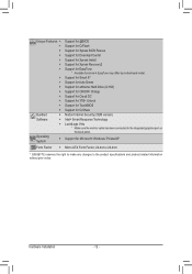
... Center ŠŠ Support for Xpress Install ŠŠ Support for Xpress Recovery2 ŠŠ Support for EasyTune * Available functions in EasyTune may differ by motherboard model. ŠŠ Support for Smart 6™ ŠŠ Support for Auto Green ŠŠ Support for eXtreme Hard Drive (X.H.D) ŠŠ Support... for TouchBIOS ŠŠ Support for Microsoft® Windows 7/Vista/XP Form Factor ŠŠ Micro ATX Form Factor; 24.4cm x 24.4cm * GIGABYTE reserves the right to make any changes to the integrated graphics port on the back panel.
... Center ŠŠ Support for Xpress Install ŠŠ Support for Xpress Recovery2 ŠŠ Support for EasyTune * Available functions in EasyTune may differ by motherboard model. ŠŠ Support for Smart 6™ ŠŠ Support for Auto Green ŠŠ Support for eXtreme Hard Drive (X.H.D) ŠŠ Support... for TouchBIOS ŠŠ Support for Microsoft® Windows 7/Vista/XP Form Factor ŠŠ Micro ATX Form Factor; 24.4cm x 24.4cm * GIGABYTE reserves the right to make any changes to the integrated graphics port on the back panel.
Manual
Page 13
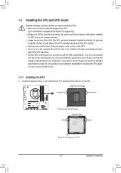
.... •• Do not turn on the computer if the CPU cooler is not recommended that the motherboard supports the CPU. (Go to GIGABYTE's website for the peripherals. Locate the alignment keys on the motherboard CPU socket and the notches on the surface of the CPU may locate the notches on both sides...
.... •• Do not turn on the computer if the CPU cooler is not recommended that the motherboard supports the CPU. (Go to GIGABYTE's website for the peripherals. Locate the alignment keys on the motherboard CPU socket and the notches on the surface of the CPU may locate the notches on both sides...
Manual
Page 14
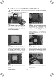
Hold your thumb to lift up the front edge (next to correctly install the CPU into the motherboard CPU socket. To protect the CPU socket, always replace the protective socket cover when the CPU is properly inserted, use your index finger down and ...
Hold your thumb to lift up the front edge (next to correctly install the CPU into the motherboard CPU socket. To protect the CPU socket, always replace the protective socket cover when the CPU is properly inserted, use your index finger down and ...
Manual
Page 15
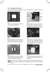
...installing the cooler.) Step 5: After the installation, check the back of the CPU cooler to the CPU fan header (CPU_FAN) on the motherboard. If the push pin is inserted as the example cooler.) Direction of the Arrow Sign on the Male Push Pin Male Push Pin The...direction of the installed CPU. Hardware Installation Step 6: Finally, attach the power connector of the motherboard. 1-3-2 Installing the CPU Cooler Follow the steps below to correctly install the CPU cooler on the motherboard. (The following procedure uses Intel® boxed cooler as the picture above shows, the installation...
...installing the cooler.) Step 5: After the installation, check the back of the CPU cooler to the CPU fan header (CPU_FAN) on the motherboard. If the push pin is inserted as the example cooler.) Direction of the Arrow Sign on the Male Push Pin Male Push Pin The...direction of the installed CPU. Hardware Installation Step 6: Finally, attach the power connector of the motherboard. 1-3-2 Installing the CPU Cooler Follow the steps below to correctly install the CPU cooler on the motherboard. (The following procedure uses Intel® boxed cooler as the picture above shows, the installation...
Manual
Page 16
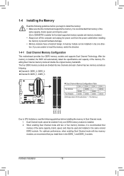
...-Sided, "- -"=No Memory) DDR3_4 DDR3_2 DDR3_3 DDR3_1 Due to CPU limitations, read the following guidelines before installing the memory to GIGABYTE's website for the latest supported memory speeds and memory modules.) •• Always turn off the computer and unplug the power ... to insert the memory, switch the direction. 1-4-1 Dual Channel Memory Configuration This motherboard provides four DDR3 memory sockets and supports Dual Channel Technology. After the memory is recommended that the motherboard supports the memory. Hardware Installation - 16 - It is installed, the BIOS...
...-Sided, "- -"=No Memory) DDR3_4 DDR3_2 DDR3_3 DDR3_1 Due to CPU limitations, read the following guidelines before installing the memory to GIGABYTE's website for the latest supported memory speeds and memory modules.) •• Always turn off the computer and unplug the power ... to insert the memory, switch the direction. 1-4-1 Dual Channel Memory Configuration This motherboard provides four DDR3 memory sockets and supports Dual Channel Technology. After the memory is recommended that the motherboard supports the memory. Hardware Installation - 16 - It is installed, the BIOS...
Manual
Page 17
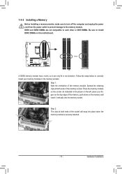
.... - 17 - Spread the retaining clips at both ends of the socket will snap into the memory socket. Hardware Installation Place the memory module on this motherboard. Step 2: The clips at both ends of the memory socket. Step 1: Note the orientation of the memory, push down on the top edge of the...
.... - 17 - Spread the retaining clips at both ends of the socket will snap into the memory socket. Hardware Installation Place the memory module on this motherboard. Step 2: The clips at both ends of the memory socket. Step 1: Note the orientation of the memory, push down on the top edge of the...
Manual
Page 18
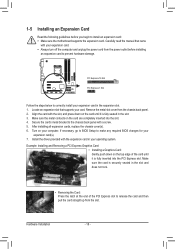
... card and then pull the card straight up from the power outlet before you begin to install an expansion card: •• Make sure the motherboard supports the expansion card. 1-5 Installing an Expansion Card Read the following guidelines before installing an expansion card to prevent hardware damage. Hardware Installation - 18...
... card and then pull the card straight up from the power outlet before you begin to install an expansion card: •• Make sure the motherboard supports the expansion card. 1-5 Installing an Expansion Card Read the following guidelines before installing an expansion card to prevent hardware damage. Hardware Installation - 18...
Manual
Page 20
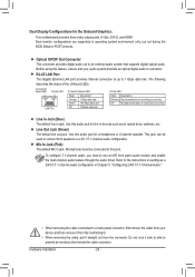
...or 2-channel speaker. Refer to the instructions on setting up to an external audio system that your device and then remove it from the motherboard. •• When removing the cable, pull it side to side to use an HD front panel audio module and enable the ...environment only, but not during the BIOS Setup or POST process. Hardware Installation - 20 - Before using this audio jack for the Onboard Graphics: This motherboard provides three video output ports: D-Sub, DVI-D, and HDMI. Optical S/PDIF Out Connector This connector provides digital audio out to 1 Gbps data rate...
...or 2-channel speaker. Refer to the instructions on setting up to an external audio system that your device and then remove it from the motherboard. •• When removing the cable, pull it side to side to use an HD front panel audio module and enable the ...environment only, but not during the BIOS Setup or POST process. Hardware Installation - 20 - Before using this audio jack for the Onboard Graphics: This motherboard provides three video output ports: D-Sub, DVI-D, and HDMI. Optical S/PDIF Out Connector This connector provides digital audio out to 1 Gbps data rate...
Manual
Page 21
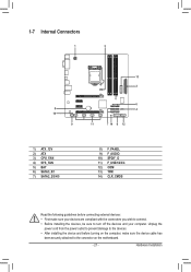
... and your devices are compliant with the connectors you wish to connect. •• Before installing the devices, be sure to the connector on the motherboard. - 21 - 1-7 Internal Connectors 1 3 5 10 9 13 2 6 4 11 7 14 8 12 1) ATX_12V 2) ATX 3) CPU_FAN 4) SYS_FAN 5) BAT 6) SATA3_0/1 7) SATA2_2/3/4/5 8) F_PANEL 9) F_AUDIO 10) SPDIF_O 11) F_USB1/2/3/4 12) COM 13) TPM...
... and your devices are compliant with the connectors you wish to connect. •• Before installing the devices, be sure to the connector on the motherboard. - 21 - 1-7 Internal Connectors 1 3 5 10 9 13 2 6 4 11 7 14 8 12 1) ATX_12V 2) ATX 3) CPU_FAN 4) SYS_FAN 5) BAT 6) SATA3_0/1 7) SATA2_2/3/4/5 8) F_PANEL 9) F_AUDIO 10) SPDIF_O 11) F_USB1/2/3/4 12) COM 13) TPM...
Manual
Page 22
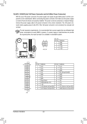
... the power supply is not connected, the computer will not start. If the 12V power connector is turned off and all the components on the motherboard. To meet expansion requirements, it is used (500W or greater). The power connector possesses a foolproof design. If a power supply is recommended that a power supply that...
... the power supply is not connected, the computer will not start. If the 12V power connector is turned off and all the components on the motherboard. To meet expansion requirements, it is used (500W or greater). The power connector possesses a foolproof design. If a power supply is recommended that a power supply that...
Manual
Page 23
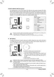
... •• Contact the place of explosion if the battery is replaced with fan speed control design. 3/4) CPU_FAN/SYS_FAN (Fan Headers) The motherboard has a 4-pin CPU fan header (CPU_FAN) and a 4-pin system fan header (SYS_FAN). Most fan headers possess a foolproof insertion design. ...You may hang. •• These fan headers are not able to prevent your - Hardware Installation The motherboard supports CPU fan speed control, which requires the use a metal object like a screwdriver to connect it is recommended that a system fan...
... •• Contact the place of explosion if the battery is replaced with fan speed control design. 3/4) CPU_FAN/SYS_FAN (Fan Headers) The motherboard has a 4-pin CPU fan header (CPU_FAN) and a 4-pin system fan header (SYS_FAN). Most fan headers possess a foolproof insertion design. ...You may hang. •• These fan headers are not able to prevent your - Hardware Installation The motherboard supports CPU fan speed control, which requires the use a metal object like a screwdriver to connect it is recommended that a system fan...


