User Manual
Page 4
Table of Contents Box Contents...6 Optional Items...6 GA-X79-UD7 Motherboard Layout 7 GA-X79-UD7 Motherboard Block Diagram 8 Chapter 1 Hardware Installation 9 1-1 Installation Precautions 9 1-2 Product Specifications 10 1-3 Installing the CPU and CPU Cooler 13 1-3-1 Installing the CPU 13 1-3-2 Installing the CPU ... 1-8 Onboard Buttons 22 1-9 Internal Connectors 24 Chapter 2 BIOS Setup 35 2-1 Startup Screen 36 2-2 The Main Menu 37 2-3 M.I.T...39 2-4 System...52 2-5 BIOS Features 53 2-6 Peripherals...55 2-7 Power Management 58 2-8 Save & Exit Setup 60 - 4 -
Table of Contents Box Contents...6 Optional Items...6 GA-X79-UD7 Motherboard Layout 7 GA-X79-UD7 Motherboard Block Diagram 8 Chapter 1 Hardware Installation 9 1-1 Installation Precautions 9 1-2 Product Specifications 10 1-3 Installing the CPU and CPU Cooler 13 1-3-1 Installing the CPU 13 1-3-2 Installing the CPU ... 1-8 Onboard Buttons 22 1-9 Internal Connectors 24 Chapter 2 BIOS Setup 35 2-1 Startup Screen 36 2-2 The Main Menu 37 2-3 M.I.T...39 2-4 System...52 2-5 BIOS Features 53 2-6 Peripherals...55 2-7 Power Management 58 2-8 Save & Exit Setup 60 - 4 -
User Manual
Page 6
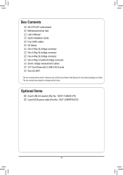
Box Contents GA-X79-UD7 motherboard Motherboard driver disk User's Manual Quick Installation Guide Four SATA cables I/O Shield One 2-Way SLI bridge connector One 3-Way SLI bridge connector One 4-Way ... 3.0/2.0 ports One GC-WIFI The box contents above are subject to change without notice. Optional Items 2-port USB 2.0 bracket (Part No. 12CR1-1UB030-5*R) 2-port SATA power cable (Part No. 12CF1-2SERPW-0*R) - 6 - The box contents are for reference only and the actual items shall depend on the product package you obtain.
Box Contents GA-X79-UD7 motherboard Motherboard driver disk User's Manual Quick Installation Guide Four SATA cables I/O Shield One 2-Way SLI bridge connector One 3-Way SLI bridge connector One 4-Way ... 3.0/2.0 ports One GC-WIFI The box contents above are subject to change without notice. Optional Items 2-port USB 2.0 bracket (Part No. 12CR1-1UB030-5*R) 2-port SATA power cable (Part No. 12CF1-2SERPW-0*R) - 6 - The box contents are for reference only and the actual items shall depend on the product package you obtain.

User Manual
Page 9
...uncertain about any metal leads or connectors. •• It is suitable for warranty validation. •• Always remove the AC power by your hands dry and first touch a metal object to eliminate static electricity. •• Prior to installing the motherboard, please ... or metal components placed on the motherboard or within an electrostatic shielding container. •• Before unplugging the power supply cable from the power outlet before installing or removing the motherboard or other hardware components. •• When connecting hardware components to ...
...uncertain about any metal leads or connectors. •• It is suitable for warranty validation. •• Always remove the AC power by your hands dry and first touch a metal object to eliminate static electricity. •• Prior to installing the motherboard, please ... or metal components placed on the motherboard or within an electrostatic shielding container. •• Before unplugging the power supply cable from the power outlet before installing or removing the motherboard or other hardware components. •• When connecting hardware components to ...
User Manual
Page 11
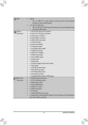
... the back panel, 2 ports available through the internal USB header) ŠŠ 1 x 24-pin ATX main power connector ŠŠ 2 x 8-pin ATX 12V power connectors ŠŠ 2 x PCIe power connectors ŠŠ 6 x SATA 6Gb/s connectors ŠŠ 4 x SATA 3Gb/s connectors ŠŠ...x S/PDIF Out header ŠŠ 3 x USB 2.0/1.1 headers ŠŠ 1 x USB 3.0/2.0 header ŠŠ 1 x Clear CMOS jumper ŠŠ 1 x power button ŠŠ 1 x reset button ŠŠ 1 x onboard voltage measurement module ŠŠ 1 x Gear button ŠŠ 1 x CPU BCLK Down button...
... the back panel, 2 ports available through the internal USB header) ŠŠ 1 x 24-pin ATX main power connector ŠŠ 2 x 8-pin ATX 12V power connectors ŠŠ 2 x PCIe power connectors ŠŠ 6 x SATA 6Gb/s connectors ŠŠ 4 x SATA 3Gb/s connectors ŠŠ...x S/PDIF Out header ŠŠ 3 x USB 2.0/1.1 headers ŠŠ 1 x USB 3.0/2.0 header ŠŠ 1 x Clear CMOS jumper ŠŠ 1 x power button ŠŠ 1 x reset button ŠŠ 1 x onboard voltage measurement module ŠŠ 1 x Gear button ŠŠ 1 x CPU BCLK Down button...
User Manual
Page 13
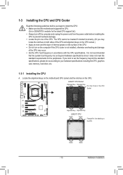
...even and thin layer of thermal grease on the computer if the CPU cooler is not recommended that the motherboard supports the CPU. (Go to GIGABYTE's website for the peripherals. If you begin to install the CPU: •• Make sure that the system bus frequency be inserted if ...list.) •• Always turn on the surface of the CPU. •• Do not turn off the computer and unplug the power cord from the power outlet before you wish to set beyond the standard specifications, please do so according to your hardware specifications including the CPU, graphics card, ...
...even and thin layer of thermal grease on the computer if the CPU cooler is not recommended that the motherboard supports the CPU. (Go to GIGABYTE's website for the peripherals. If you begin to install the CPU: •• Make sure that the system bus frequency be inserted if ...list.) •• Always turn on the surface of the CPU. •• Do not turn off the computer and unplug the power cord from the power outlet before you wish to set beyond the standard specifications, please do so according to your hardware specifications including the CPU, graphics card, ...
User Manual
Page 14
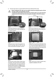
... of engaging the lever. Then secure lever B under its retention tab. B. The protective plastic cover may pop off the computer and unplug the power cord from the socket. Save the cover properly and always replace it . Follow the steps below referred as lever B) down and away from the... socket to the "unlock" marking " " (below referred as lever A) down and away from the power outlet to prevent damage to rise. Lever A Lever B Step 1: Push the lever closest to release it when the CPU is not installed. Step 2: Push...
... of engaging the lever. Then secure lever B under its retention tab. B. The protective plastic cover may pop off the computer and unplug the power cord from the socket. Save the cover properly and always replace it . Follow the steps below referred as lever B) down and away from the... socket to the "unlock" marking " " (below referred as lever A) down and away from the power outlet to prevent damage to rise. Lever A Lever B Step 1: Push the lever closest to release it when the CPU is not installed. Step 2: Push...
User Manual
Page 15
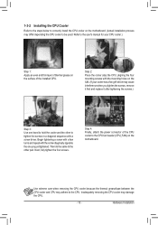
... header (CPU_FAN) on the surface of the installed CPU. Inadequately removing the CPU cooler may cause interference when you just tightened. Step 4: Finally, attach the power connector of thermal grease on the motherboard. Then do the same to the CPU. Use extreme care when removing the CPU cooler because the thermal...
... header (CPU_FAN) on the surface of the installed CPU. Inadequately removing the CPU cooler may cause interference when you just tightened. Step 4: Finally, attach the power connector of thermal grease on the motherboard. Then do the same to the CPU. Use extreme care when removing the CPU cooler because the thermal...
User Manual
Page 16
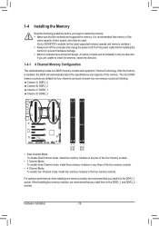
... that memory of the same capacity, brand, speed, and chips be used. (Go to GIGABYTE's website for the latest supported memory speeds and memory modules.) •• Always turn off the computer and unplug the power cord from the power outlet before installing the memory to insert the memory, switch the direction. 1-4-1 4 Channel...
... that memory of the same capacity, brand, speed, and chips be used. (Go to GIGABYTE's website for the latest supported memory speeds and memory modules.) •• Always turn off the computer and unplug the power cord from the power outlet before installing the memory to insert the memory, switch the direction. 1-4-1 4 Channel...

User Manual
Page 17
... at both ends of the memory socket. 1-4-2 Installing a Memory Before installing a memory module, make sure to turn off the computer and unplug the power cord from the power outlet to prevent damage to correctly install your fingers on the top edge of the memory, push down on the memory and insert it...
... at both ends of the memory socket. 1-4-2 Installing a Memory Before installing a memory module, make sure to turn off the computer and unplug the power cord from the power outlet to prevent damage to correctly install your fingers on the top edge of the memory, push down on the memory and insert it...
User Manual
Page 18
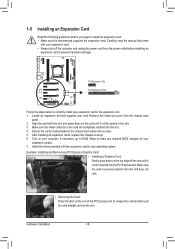
...your expansion card in the slot. 3. After installing all expansion cards, replace the chassis cover(s). 6. Remove the metal slot cover from the power outlet before you begin to install an expansion card: •• Make sure the motherboard supports the expansion card. Example: Installing and ... of the card until it is securely seated in your expansion card. •• Always turn off the computer and unplug the power cord from the chassis back panel. 2. 1-5 Installing an Expansion Card Read the following guidelines before installing an expansion card to prevent ...
...your expansion card in the slot. 3. After installing all expansion cards, replace the chassis cover(s). 6. Remove the metal slot cover from the power outlet before you begin to install an expansion card: •• Make sure the motherboard supports the expansion card. Example: Installing and ... of the card until it is securely seated in your expansion card. •• Always turn off the computer and unplug the power cord from the chassis back panel. 2. 1-5 Installing an Expansion Card Read the following guidelines before installing an expansion card to prevent ...
User Manual
Page 19
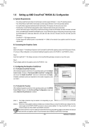
...that came with your graphics cards for enabling CrossFireX/SLI technology may be needed or not depending on your graphics cards for the power requirement) B. Hardware Installation Two/three/four CrossFireX/SLI-ready graphics cards of the ATX4P1 and ATX4P4 connectors. Current GPUs that ... stability. Step 3: Plug the display cable into the graphics card on the number of graphics cards you connect the SATA power cable(s) from the power supply to the ATX4P1/ATX4P4 connector to the Catalyst Control Center. The 2-Way CrossFireX and 2-Way SLI technologies currently support ...
...that came with your graphics cards for enabling CrossFireX/SLI technology may be needed or not depending on your graphics cards for the power requirement) B. Hardware Installation Two/three/four CrossFireX/SLI-ready graphics cards of the ATX4P1 and ATX4P4 connectors. Current GPUs that ... stability. Step 3: Plug the display cable into the graphics card on the number of graphics cards you connect the SATA power cable(s) from the power supply to the ATX4P1/ATX4P4 connector to the Catalyst Control Center. The 2-Way CrossFireX and 2-Way SLI technologies currently support ...
User Manual
Page 22
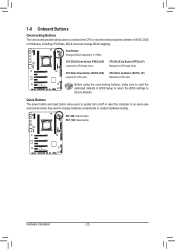
Quick Buttons The power button and reset button allow users to overclock the CPU in real-time and at anytime (whether in BIOS, DOS or Windows), including CPU Ratio, ... sure to load the optimized defaults in BIOS Setup to return the BIOS settings to 0.1 MHz. Gear Button: Changes BCLK stepping to factory defaults. PW_SW: Power button RST_SW: Reset button Hardware Installation - 22 - CPU BCLK Down Button (FREQ_DW) Lowers the CPU base clock. 1-8 Onboard Buttons Overclocking Buttons The overclocking buttons allow...
Quick Buttons The power button and reset button allow users to overclock the CPU in real-time and at anytime (whether in BIOS, DOS or Windows), including CPU Ratio, ... sure to load the optimized defaults in BIOS Setup to return the BIOS settings to 0.1 MHz. Gear Button: Changes BCLK stepping to factory defaults. PW_SW: Power button RST_SW: Reset button Hardware Installation - 22 - CPU BCLK Down Button (FREQ_DW) Lowers the CPU base clock. 1-8 Onboard Buttons Overclocking Buttons The overclocking buttons allow...
User Manual
Page 23
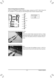
...header and your multimeter as shown. Definition 1 +12V 2 GND CLR_CMOS CLR_CMOSC CI CI CI DIS_ME DIS_ME DI GP15_CPT GP15_CPT G (GA-IVB) (GA-IVB) (G XDP_CPU XDP_CPU X XDP_PCH XDP_PCH X (GA-IVB) (GA-IVB) (G Hardware Installation DIP 1 23 1 DIP 1 23 1 DIP 1 23 1 DIP 1 23 1 DIP 1 ...1 DDRVTT DIP 1 23 DIP 1 23 DIP 1 23 DIP 1 23 DIP 1 23 DIP DIP 1 23 PCIe power cPoCnIneepctoowr e(Sr AcPoTCnAIne)(eXpc5oto8wrAe(-rSOcAPCoTCn)AIne)e(Xpc5too8wrAe(-SrOAcPCoTCnA)In)e(eXpc5oto8wrAe(-SrOcAPCoTCn)AIne)(eXpco5tow8rAe(-rSOcAPCoTCn)AIne)e(Xpcot5ow8rAe(Sr-OcAoCTnA)n)e(Xc5to8rA(-SOACT)A)(X58A-...
...header and your multimeter as shown. Definition 1 +12V 2 GND CLR_CMOS CLR_CMOSC CI CI CI DIS_ME DIS_ME DI GP15_CPT GP15_CPT G (GA-IVB) (GA-IVB) (G XDP_CPU XDP_CPU X XDP_PCH XDP_PCH X (GA-IVB) (GA-IVB) (G Hardware Installation DIP 1 23 1 DIP 1 23 1 DIP 1 23 1 DIP 1 23 1 DIP 1 ...1 DDRVTT DIP 1 23 DIP 1 23 DIP 1 23 DIP 1 23 DIP 1 23 DIP DIP 1 23 PCIe power cPoCnIneepctoowr e(Sr AcPoTCnAIne)(eXpc5oto8wrAe(-rSOcAPCoTCn)AIne)e(Xpc5too8wrAe(-SrOAcPCoTCnA)In)e(eXpc5oto8wrAe(-SrOcAPCoTCn)AIne)(eXpco5tow8rAe(-rSOcAPCoTCn)AIne)e(Xpcot5ow8rAe(Sr-OcAoCTnA)n)e(Xc5to8rA(-SOACT)A)(X58A-...
User Manual
Page 24
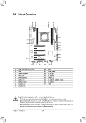
...) SPDIF_O 15) F_USB1/F_USB2/F_USB3 16) F_USB30 17) TPM Read the following guidelines before turning on the motherboard. Hardware Installation - 24 - Unplug the power cord from the power outlet to prevent damage to the devices. •• After installing the device and before connecting external devices: •• First make sure the...
...) SPDIF_O 15) F_USB1/F_USB2/F_USB3 16) F_USB30 17) TPM Read the following guidelines before turning on the motherboard. Hardware Installation - 24 - Unplug the power cord from the power outlet to prevent damage to the devices. •• After installing the device and before connecting external devices: •• First make sure the...

User Manual
Page 25
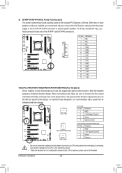
...ATX (2x4 12V Power Connectors and 2x12 Main Power Connector) With the use of the power connector, the power supply can supply enough stable power to the CPU. Before connecting the power connector, first make sure the power supply is not connected, the computer will not start. The 12V power connector mainly supplies power to all devices ...: Pin No. 1 2 3 4 5 6 7 8 9 10 11 12 Definition Pin No. 3.3V 13 3.3V 14 GND 15 +5V 16 GND 17 +5V 18 GND 19 Power Good 20 5VSB (stand by +5V) 21 +12V 22 +12V (Only for 2x12-pin ATX) 23 3.3V (Only for 2x12-pin ATX) 24 Definition 3.3V...
...ATX (2x4 12V Power Connectors and 2x12 Main Power Connector) With the use of the power connector, the power supply can supply enough stable power to the CPU. Before connecting the power connector, first make sure the power supply is not connected, the computer will not start. The 12V power connector mainly supplies power to all devices ...: Pin No. 1 2 3 4 5 6 7 8 9 10 11 12 Definition Pin No. 3.3V 13 3.3V 14 GND 15 +5V 16 GND 17 +5V 18 GND 19 Power Good 20 5VSB (stand by +5V) 21 +12V 22 +12V (Only for 2x12-pin ATX) 23 3.3V (Only for 2x12-pin ATX) 24 Definition 3.3V...
User Manual
Page 26
... fan with fan speed control design. Hardware Installation - 26 - The speed control function requires the use of the ATX4P1 and ATX4P4 connectors. 1 DIP 1 23 PCIe power connector (SATA)(X58A-OC) DIP 1 23 1 DIP 1 23 1 Voltage measurement module(X58A-OC) DB_PORT Pin No. Definition 1 NC 2 NC 1 3 NC... control function. F_PANEL(NH) PWM Switch (X58A-OC) BIOS Switcher (X58A-OC) 1 M_SATA 3) ATX4P1/ATX4P4 (PCIe Power Connectors) The power connectors provide auxiliary power to the CPU or the system may hang. •• These fan headers are not configuration jumper blocks. When two...
... fan with fan speed control design. Hardware Installation - 26 - The speed control function requires the use of the ATX4P1 and ATX4P4 connectors. 1 DIP 1 23 PCIe power connector (SATA)(X58A-OC) DIP 1 23 1 DIP 1 23 1 Voltage measurement module(X58A-OC) DB_PORT Pin No. Definition 1 NC 2 NC 1 3 NC... control function. F_PANEL(NH) PWM Switch (X58A-OC) BIOS Switcher (X58A-OC) 1 M_SATA 3) ATX4P1/ATX4P4 (PCIe Power Connectors) The power connectors provide auxiliary power to the CPU or the system may hang. •• These fan headers are not configuration jumper blocks. When two...
User Manual
Page 29
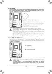
...regulations. 11) CLR_CMOS (Clear CMOS Jumper) Use this jumper to factory defaults. Plug in the power cord and restart your computer. •• Always turn off your computer and unplug the power cord before clearing the CMOS values. •• After system restart, go to BIOS Setup ...Setup," for one . Open: Normal Short: Clear CMOS Values •• Always turn off your computer and unplug the power cord. 2. 10) BAT (Battery) The battery provides power to keep the values (such as BIOS configurations, date, and time information) in the CMOS when the computer is replaced with...
...regulations. 11) CLR_CMOS (Clear CMOS Jumper) Use this jumper to factory defaults. Plug in the power cord and restart your computer. •• Always turn off your computer and unplug the power cord before clearing the CMOS values. •• After system restart, go to BIOS Setup ...Setup," for one . Open: Normal Short: Clear CMOS Values •• Always turn off your computer and unplug the power cord. 2. 10) BAT (Battery) The battery provides power to keep the values (such as BIOS configurations, date, and time information) in the CMOS when the computer is replaced with...
User Manual
Page 30
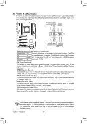
... this header, make sure the wire assignments and the pin assignments are matched correctly. Hard Drive Activity LED Reset Switch Power LED Chassis Intrusion Header •• MSG/PWR (Message/Power/Sleep LED, Yellow/Purple): System Status LED Connects to the pin assignments below. The LED is S0 On on when... the system is in S3/S4 sleep state Off or powered off (S5). •• PW (Power Switch, Red): Connects to the speaker on the chassis front panel. The LED is off your chassis front panel module to ...
... this header, make sure the wire assignments and the pin assignments are matched correctly. Hard Drive Activity LED Reset Switch Power LED Chassis Intrusion Header •• MSG/PWR (Message/Power/Sleep LED, Yellow/Purple): System Status LED Connects to the pin assignments below. The LED is S0 On on when... the system is in S3/S4 sleep state Off or powered off (S5). •• PW (Power Switch, Red): Connects to the speaker on the chassis front panel. The LED is off your chassis front panel module to ...
User Manual
Page 31
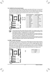
... the module connector and the motherboard header will be present on how to this header. Definition 9 1 1 MIC2_L 2 F_PAGNENLD(NH) 3 MIC2_R 1 MIC 2 GND 3 MIC Power 10 2 4 -ACZ_DET 5 LINE2_R 4 NC 5 Line Out (R) 6 GND 6 NC 7 FAUDIO_JD 7 NC 8 No Pin 8 No Pin 9 LINE2_L 9 Line Out (L) ...output from the HDMI display at the same time. Definition Pin No. Definition 1 SPDIFO 1 2 GND ACPI_CPT (GA-IVB) SMB_CPT (GA-IVB) CLR_CMOS CI DIS_ME GP15_CPT (GA-IVB) XDP_CPU XDP_PCH (GA-IVB) - 31 - DIP 14) SPDIF_O (S/PDIF Out Header) 1 23 This header supports digital S/PDIF Out ...
... the module connector and the motherboard header will be present on how to this header. Definition 9 1 1 MIC2_L 2 F_PAGNENLD(NH) 3 MIC2_R 1 MIC 2 GND 3 MIC Power 10 2 4 -ACZ_DET 5 LINE2_R 4 NC 5 Line Out (R) 6 GND 6 NC 7 FAUDIO_JD 7 NC 8 No Pin 8 No Pin 9 LINE2_L 9 Line Out (L) ...output from the HDMI display at the same time. Definition Pin No. Definition 1 SPDIFO 1 2 GND ACPI_CPT (GA-IVB) SMB_CPT (GA-IVB) CLR_CMOS CI DIS_ME GP15_CPT (GA-IVB) XDP_CPU XDP_PCH (GA-IVB) - 31 - DIP 14) SPDIF_O (S/PDIF Out Header) 1 23 This header supports digital S/PDIF Out ...
User Manual
Page 32
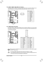
.../OFF Charge function. •• Do not plug the IEEE 1394 bracket (2x5-pin) cable into a free 3.5" drive bay of your computer and unplug the power cord from the 3.5" front panel to USB 3.0/2.0 specification and can provide two USB ports. T Pin No. Hardware Installation - 32 - For purchasing the optional USB ... 11 12 13 14 15 16 17 18 19 20 Definition D2+ D2GND SSTX2+ SSTX2GND SSRX2+ SSRX2VBUS No Pin Voltage measurement module(X58A-OC) PCIe power connector (SATA)(X58A-O When the system is in S4/S5 mode, only the USB ports routed to the F_USB1 header can provide two USB ports...
.../OFF Charge function. •• Do not plug the IEEE 1394 bracket (2x5-pin) cable into a free 3.5" drive bay of your computer and unplug the power cord from the 3.5" front panel to USB 3.0/2.0 specification and can provide two USB ports. T Pin No. Hardware Installation - 32 - For purchasing the optional USB ... 11 12 13 14 15 16 17 18 19 20 Definition D2+ D2GND SSTX2+ SSTX2GND SSRX2+ SSRX2VBUS No Pin Voltage measurement module(X58A-OC) PCIe power connector (SATA)(X58A-O When the system is in S4/S5 mode, only the USB ports routed to the F_USB1 header can provide two USB ports...


