
Manual
Page 1
... drive is greater than or equal to enhance your hard drive read/write performance without the need for RAID 0. A. Using GIGABYTE eXtreme Hard Drive (X.H.D) Instructions:(Note 2) Before launching X.H.D, make sure the newly added harddrive has equal or greater capacity than the... RAID array: (Note 3): Click Manual to load the SATA controller driver first. To manually set up all motherboard drivers, including the X.H.D utility. eXtreme Hard Drive (X.H.D) With GIGABYTE eXtreme Hard Drive (X.H.D)(Note 1), users can build a RAID 0, RAID 1, or other supported RAID array depending...
... drive is greater than or equal to enhance your hard drive read/write performance without the need for RAID 0. A. Using GIGABYTE eXtreme Hard Drive (X.H.D) Instructions:(Note 2) Before launching X.H.D, make sure the newly added harddrive has equal or greater capacity than the... RAID array: (Note 3): Click Manual to load the SATA controller driver first. To manually set up all motherboard drivers, including the X.H.D utility. eXtreme Hard Drive (X.H.D) With GIGABYTE eXtreme Hard Drive (X.H.D)(Note 1), users can build a RAID 0, RAID 1, or other supported RAID array depending...

Manual
Page 1
GA-X58A-UD3R LGA1366 socket motherboard for Intel® Core™ i7 processor family User's Manual Rev. 1002 12ME-X58AU3R-1002R
GA-X58A-UD3R LGA1366 socket motherboard for Intel® Core™ i7 processor family User's Manual Rev. 1002 12ME-X58AU3R-1002R

Manual
Page 2
Motherboard GA-X58A-UD3R Jan. 8, 2010 Motherboard GA-X58A-UD3R Jan. 8, 2010
Motherboard GA-X58A-UD3R Jan. 8, 2010 Motherboard GA-X58A-UD3R Jan. 8, 2010
Manual
Page 3
..., transmitted, or published in this manual is 1.0. All rights reserved. Disclaimer Information in the use GIGABYTE's unique features, read or download the information on/from the Support&Downloads\Motherboard\Technology Guide page on your motherboard revision before updating motherboard BIOS, drivers, or when looking for technical information. For example, "REV: 1.0" means the revision of...
..., transmitted, or published in this manual is 1.0. All rights reserved. Disclaimer Information in the use GIGABYTE's unique features, read or download the information on/from the Support&Downloads\Motherboard\Technology Guide page on your motherboard revision before updating motherboard BIOS, drivers, or when looking for technical information. For example, "REV: 1.0" means the revision of...
Manual
Page 4
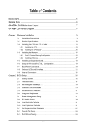
Table of Contents Box Contents...6 Optional Items...6 GA-X58A-UD3R Motherboard Layout 7 GA-X58A-UD3R Block Diagram 8 Chapter 1 Hardware Installation 9 1-1 Installation Precautions 9 1-2 Product Specifications 10 1-3 Installing the CPU and CPU Cooler 13 1-3-1 Installing the CPU 13 1-3-2 Installing the CPU Cooler ...
Table of Contents Box Contents...6 Optional Items...6 GA-X58A-UD3R Motherboard Layout 7 GA-X58A-UD3R Block Diagram 8 Chapter 1 Hardware Installation 9 1-1 Installation Precautions 9 1-2 Product Specifications 10 1-3 Installing the CPU and CPU Cooler 13 1-3-1 Installing the CPU 13 1-3-2 Installing the CPU Cooler ...

Manual
Page 6
...power cable (Part No. 12CF1-2SERPW-0*R) S/PDIF In cable (Part No. 12CR1-1SPDIN-0*R) - 6 - The box contents are for reference only. Box Contents GA-X58A-UD3R motherboard Motherboard driver disk User's Manual Quick Installation Guide One IDE cable Four SATA 3Gb/s cables I/O Shield 2-Way SLI bridge connector 3-Way SLI bridge connector • ...The box contents above are subject to change without notice. • The motherboard image is for reference only and the actual items shall depend on the product package you obtain.
...power cable (Part No. 12CF1-2SERPW-0*R) S/PDIF In cable (Part No. 12CR1-1SPDIN-0*R) - 6 - The box contents are for reference only. Box Contents GA-X58A-UD3R motherboard Motherboard driver disk User's Manual Quick Installation Guide One IDE cable Four SATA 3Gb/s cables I/O Shield 2-Way SLI bridge connector 3-Way SLI bridge connector • ...The box contents above are subject to change without notice. • The motherboard image is for reference only and the actual items shall depend on the product package you obtain.
Manual
Page 7
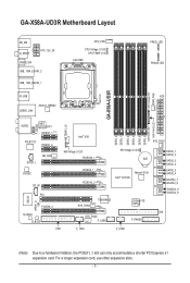
GA-X58A-UD3R Motherboard Layout KB_MS R_SPDIF ATX_12V_2X CMOS_SW USB_1394_ESATA_2 USB_1394_ESATA_1 CPU_FAN CPU Voltage L1/2/3 CPU TEMP L1/2 LGA1366 FREQ. LED PHASE LED DDR Voltage LED PWR_FAN GA-X58A-UD3R R_USB ATX USB30_LAN JMicron JMB362 DDR3_4 DDR3_3 DDR3_6 DDR3_5 NB PHASE LED DDR PHASE ... NB Voltage L1/2/3 PCIEX16_1 PCIEX8_1 PCIEX16_2 SB Voltage L1/2/3 BAT Intel® ICH10R Marvell 9128 SYS_FAN3 TSB43AB23 SYS_FAN2 F_USB2 GIGABYTE SATA2 F_PANEL SATA2_1 SATA2_0 SATA2_3 SATA2_2 SATA2_5 SATA2_4 GSATA3_7 GSATA3_6 GSATA2_9 GSATA2_8 IDE FDD F_1394 F_USB1 (Note) Due to a...
GA-X58A-UD3R Motherboard Layout KB_MS R_SPDIF ATX_12V_2X CMOS_SW USB_1394_ESATA_2 USB_1394_ESATA_1 CPU_FAN CPU Voltage L1/2/3 CPU TEMP L1/2 LGA1366 FREQ. LED PHASE LED DDR Voltage LED PWR_FAN GA-X58A-UD3R R_USB ATX USB30_LAN JMicron JMB362 DDR3_4 DDR3_3 DDR3_6 DDR3_5 NB PHASE LED DDR PHASE ... NB Voltage L1/2/3 PCIEX16_1 PCIEX8_1 PCIEX16_2 SB Voltage L1/2/3 BAT Intel® ICH10R Marvell 9128 SYS_FAN3 TSB43AB23 SYS_FAN2 F_USB2 GIGABYTE SATA2 F_PANEL SATA2_1 SATA2_0 SATA2_3 SATA2_2 SATA2_5 SATA2_4 GSATA3_7 GSATA3_6 GSATA2_9 GSATA2_8 IDE FDD F_1394 F_USB1 (Note) Due to a...
Manual
Page 9
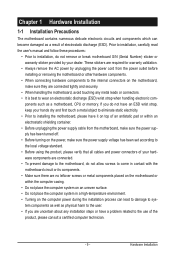
...; Turning on the computer power during the installation process can become damaged as a result of your dealer. ponents such as a motherboard, CPU or memory. Hardware Installation Prior to installation, carefully read the user's manual and follow these procedures: • Prior to...product, please verify that all cables and power connectors of electrostatic discharge (ESD). Chapter 1 Hardware Installation 1-1 Installation Precautions The motherboard contains numerous delicate electronic circuits and components which can lead to damage to system components as well as physical harm to the...
...; Turning on the computer power during the installation process can become damaged as a result of your dealer. ponents such as a motherboard, CPU or memory. Hardware Installation Prior to installation, carefully read the user's manual and follow these procedures: • Prior to...product, please verify that all cables and power connectors of electrostatic discharge (ESD). Chapter 1 Hardware Installation 1-1 Installation Precautions The motherboard contains numerous delicate electronic circuits and components which can lead to damage to system components as well as physical harm to the...
Manual
Page 12
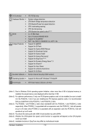
..., the actual memory size displayed will operate at up to install it is recommended that you install. (Note 6) Available functions in EasyTune may differ by motherboard model.
..., the actual memory size displayed will operate at up to install it is recommended that you install. (Note 6) Available functions in EasyTune may differ by motherboard model.
Manual
Page 13
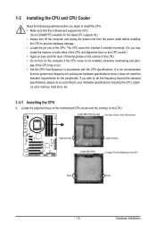
... host frequency in accordance with the CPU specifications. Locate the alignment keys on the motherboard CPU socket and the notches on the CPU Notch Notch - 13 - It is not recommended that the motherboard supports the CPU. (Go to GIGABYTE's website for the latest CPU support list.) • Always turn on the surface of...
... host frequency in accordance with the CPU specifications. Locate the alignment keys on the motherboard CPU socket and the notches on the CPU Notch Notch - 13 - It is not recommended that the motherboard supports the CPU. (Go to GIGABYTE's website for the latest CPU support list.) • Always turn on the surface of...

Manual
Page 14
... CPU socket. Step 5: Once the CPU is not installed.) Step 4: Hold the CPU with the socket alignment keys) and gently insert the CPU into the motherboard CPU socket. Hardware Installation - 14 - CPU Socket Lever Step 1: Completely raise the CPU socket lever. To protect the CPU socket, always replace the protective socket...
... CPU socket. Step 5: Once the CPU is not installed.) Step 4: Hold the CPU with the socket alignment keys) and gently insert the CPU into the motherboard CPU socket. Hardware Installation - 14 - CPU Socket Lever Step 1: Completely raise the CPU socket lever. To protect the CPU socket, always replace the protective socket...

Manual
Page 15
.... Push down each push pin. Check that the Male and Female push pins are joined closely. (Refer to the CPU fan header (CPU_FAN) on the motherboard. If the push pin is inserted as the example cooler.) Step 1: Apply an even and thin layer of thermal grease on the surface of the... the male push pin. (Turning the push pin along the direction of the CPU cooler to your CPU cooler installation manual for instructions on the motherboard. Step 6: Finally, attach the power connector of arrow is to the CPU. Step 4: You should hear a "click" when pushing down on the contrary, is to...
.... Push down each push pin. Check that the Male and Female push pins are joined closely. (Refer to the CPU fan header (CPU_FAN) on the motherboard. If the push pin is inserted as the example cooler.) Step 1: Apply an even and thin layer of thermal grease on the surface of the... the male push pin. (Turning the push pin along the direction of the CPU cooler to your CPU cooler installation manual for instructions on the motherboard. Step 6: Finally, attach the power connector of arrow is to the CPU. Step 4: You should hear a "click" when pushing down on the contrary, is to...
Manual
Page 16
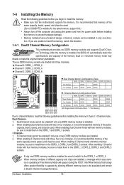
... When enabling 3 Channel mode with two memory modules, be sure to insert the memory, switch the direction. 1-4-1 Dual/3 Channel Memory Configuration This motherboard provides six DDR3 memory sockets and supports Dual/3 Channel Technology. Hardware Installation - 16 - Dual or 3 Channel memory mode may double or triple the... modules, be sure to install them in the DDR3_1 and DDR3_3 sockets. 3 Channel-1. 3 Channel mode cannot be used . (Go to GIGABYTE's website for the latest memory support list.) • Always turn off the computer and unplug the power cord from the power outlet before ...
... When enabling 3 Channel mode with two memory modules, be sure to insert the memory, switch the direction. 1-4-1 Dual/3 Channel Memory Configuration This motherboard provides six DDR3 memory sockets and supports Dual/3 Channel Technology. Hardware Installation - 16 - Dual or 3 Channel memory mode may double or triple the... modules, be sure to install them in the DDR3_1 and DDR3_3 sockets. 3 Channel-1. 3 Channel mode cannot be used . (Go to GIGABYTE's website for the latest memory support list.) • Always turn off the computer and unplug the power cord from the power outlet before ...

Manual
Page 17
... is securely inserted. - 17 - As indicated in the picture on the left, place your memory modules in one direction. Place the memory module on this motherboard. Step 2: The clips at both ends of the memory socket. Follow the steps below to correctly install your fingers on the memory and insert it...
... is securely inserted. - 17 - As indicated in the picture on the left, place your memory modules in one direction. Place the memory module on this motherboard. Step 2: The clips at both ends of the memory socket. Follow the steps below to correctly install your fingers on the memory and insert it...
Manual
Page 18
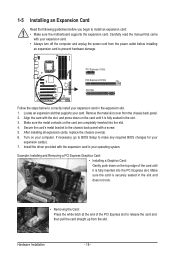
... turn off the computer and unplug the power cord from the power outlet before you begin to install an expansion card: • Make sure the motherboard supports the expansion card. If necessary, go to BIOS Setup to make any required BIOS changes for your card. Turn on the top edge of...
... turn off the computer and unplug the power cord from the power outlet before you begin to install an expansion card: • Make sure the motherboard supports the expansion card. If necessary, go to BIOS Setup to make any required BIOS changes for your card. Turn on the top edge of...
Manual
Page 19
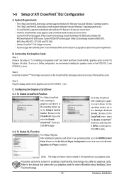
... OK to the Catalyst Control Center. For 3-Way CrossFireX: After installing the graphics card driver in the operating system, go to apply. A CrossFireX/SLI-supported motherboard with sufficient power is enabled. (Note) The bridge connectors may be needed or not depending on your graphics cards for enabling CrossFireX/SLI technology may...
... OK to the Catalyst Control Center. For 3-Way CrossFireX: After installing the graphics card driver in the operating system, go to apply. A CrossFireX/SLI-supported motherboard with sufficient power is enabled. (Note) The bridge connectors may be needed or not depending on your graphics cards for enabling CrossFireX/SLI technology may...

Manual
Page 20
... audio out to an external audio system that supports digital optical audio. Use this feature, ensure that your device and then remove it from the motherboard. • When removing the cable, pull it side to side to 1 Gbps data rate. or use this port for USB devices such as a USB keyboard...
... audio out to an external audio system that supports digital optical audio. Use this feature, ensure that your device and then remove it from the motherboard. • When removing the cable, pull it side to side to 1 Gbps data rate. or use this port for USB devices such as a USB keyboard...

Manual
Page 22
the green LED lights up when the temperature is illuminated when the temperature exceeds 80oC. 1-8 Onboard LEDs and Switches Overvoltage LEDs This motherboard contains 4 sets of overvoltage LEDs which level the CPU is overclocked. CPU TEMP Off: Below 60oC L1: 61~ 80oC (green) L2: Over 80oC (red) NB ...
the green LED lights up when the temperature is illuminated when the temperature exceeds 80oC. 1-8 Onboard LEDs and Switches Overvoltage LEDs This motherboard contains 4 sets of overvoltage LEDs which level the CPU is overclocked. CPU TEMP Off: Below 60oC L1: 61~ 80oC (green) L2: Over 80oC (red) NB ...

Manual
Page 24
..., make sure your devices are compliant with the connectors you wish to connect. • Before installing the devices, be sure to the connector on the motherboard.
..., make sure your devices are compliant with the connectors you wish to connect. • Before installing the devices, be sure to the connector on the motherboard.

Manual
Page 25
... connector in the correct orientation. Before connecting the power connector, first make sure the power supply is turned off and all the components on the motherboard. If a power supply is used (500W or greater). Hardware Installation Connect the power supply cable to all devices are properly installed. 1/2) ATX_12V_2X/ATX (2x4 12V...
... connector in the correct orientation. Before connecting the power connector, first make sure the power supply is turned off and all the components on the motherboard. If a power supply is used (500W or greater). Hardware Installation Connect the power supply cable to all devices are properly installed. 1/2) ATX_12V_2X/ATX (2x4 12V...


