Manual
Page 4
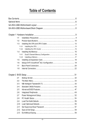
Table of Contents Box Contents...6 Optional Items...6 GA-X58-USB3 Motherboard Layout 7 GA-X58-USB3 Motherboard Block Diagram 8 Chapter 1 Hardware Installation 9 1-1 Installation Precautions 9 1-2 Product Specifications 10 1-3 Installing the CPU and CPU Cooler 13 1-3-1 Installing the CPU 13 1-3-2 Installing the CPU Cooler 15 1-4 Installing the Memory 16 1-4-1 Dual/3 Channel Memory Configuration 16 1-4-2 Installing a Memory 17 1-5 Installing an Expansion Card 18 1-6 Setup...
Table of Contents Box Contents...6 Optional Items...6 GA-X58-USB3 Motherboard Layout 7 GA-X58-USB3 Motherboard Block Diagram 8 Chapter 1 Hardware Installation 9 1-1 Installation Precautions 9 1-2 Product Specifications 10 1-3 Installing the CPU and CPU Cooler 13 1-3-1 Installing the CPU 13 1-3-2 Installing the CPU Cooler 15 1-4 Installing the Memory 16 1-4-1 Dual/3 Channel Memory Configuration 16 1-4-2 Installing a Memory 17 1-5 Installing an Expansion Card 18 1-6 Setup...
Manual
Page 8
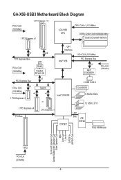
GA-X58-USB3 Motherboard Block Diagram PCIe CLK (100 MHz) 2 PCI Express x16 1 PCI Express x1 LGA1366 CPU CPU CLK+/- (133 MHz) DDR3 2200/1333/1066/800 MHz Dual/3 Channel Memory x1 x16 PCI Express Bus PCIe CLK (100 MHz) LAN RJ45 Realtek RTL8111E QPI Interface Intel® X58 IOH CLK (133 MHz) PCI Express Bus...
GA-X58-USB3 Motherboard Block Diagram PCIe CLK (100 MHz) 2 PCI Express x16 1 PCI Express x1 LGA1366 CPU CPU CLK+/- (133 MHz) DDR3 2200/1333/1066/800 MHz Dual/3 Channel Memory x1 x16 PCI Express Bus PCIe CLK (100 MHz) LAN RJ45 Realtek RTL8111E QPI Interface Intel® X58 IOH CLK (133 MHz) PCI Express Bus...

Manual
Page 9
... the power supply has been turned off. • Before turning on the computer power during the installation process can become damaged as a motherboard, CPU or memory. Hardware Installation Prior to installation, carefully read the user's manual and follow these procedures: • Prior to come in contact with the motherboard circuit or...
... the power supply has been turned off. • Before turning on the computer power during the installation process can become damaged as a motherboard, CPU or memory. Hardware Installation Prior to installation, carefully read the user's manual and follow these procedures: • Prior to come in contact with the motherboard circuit or...
Manual
Page 10
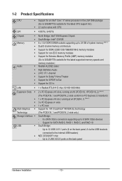
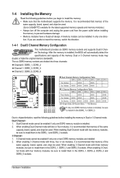
... Bridge: Intel® X58 Express Chipset South Bridge: Intel® ICH10R 6 x 1.5V DDR3 DIMM sockets supporting up to 24 GB of system memory (Note 1) Dual/3 channel memory architecture Support for DDR3 2200/1333/1066/800 MHz memory modules Support for non-ECC memory modules Support for Extreme Memory Profile (XMP) memory modules (Go to GIGABYTE's website for the...
... Bridge: Intel® X58 Express Chipset South Bridge: Intel® ICH10R 6 x 1.5V DDR3 DIMM sockets supporting up to 24 GB of system memory (Note 1) Dual/3 channel memory architecture Support for DDR3 2200/1333/1066/800 MHz memory modules Support for non-ECC memory modules Support for Extreme Memory Profile (XMP) memory modules (Go to GIGABYTE's website for the...
Manual
Page 12
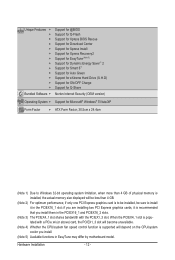
... slots. (Note 3) The PCIEX4_1 slot shares bandwidth with a PCIe x4 (or above) card, the PCIEX1_3 slot will be less than 4 GB of physical memory is installed, the actual memory size displayed will become unavailable. (Note 4) Whether the CPU/system fan speed control function is recommended that you install. (Note 5) Available functions in...
... slots. (Note 3) The PCIEX4_1 slot shares bandwidth with a PCIe x4 (or above) card, the PCIEX1_3 slot will be less than 4 GB of physical memory is installed, the actual memory size displayed will become unavailable. (Note 4) Whether the CPU/system fan speed control function is recommended that you install. (Note 5) Available functions in...

Manual
Page 13
...CPU to prevent hardware damage. • Locate the pin one of the CPU. If you wish to your hardware specifications including the CPU, graphics card, memory, hard drive, etc. 1-3-1 Installing the CPU A. The CPU cannot be set the frequency beyond the standard specifications, please do so according to set ... Corner of the CPU. • Do not turn off the computer and unplug the power cord from the power outlet before you begin to GIGABYTE's website for the peripherals. Locate the alignment keys on the motherboard CPU socket and the notches on the CPU. Hardware Installation age of the ...
...CPU to prevent hardware damage. • Locate the pin one of the CPU. If you wish to your hardware specifications including the CPU, graphics card, memory, hard drive, etc. 1-3-1 Installing the CPU A. The CPU cannot be set the frequency beyond the standard specifications, please do so according to set ... Corner of the CPU. • Do not turn off the computer and unplug the power cord from the power outlet before you begin to GIGABYTE's website for the peripherals. Locate the alignment keys on the motherboard CPU socket and the notches on the CPU. Hardware Installation age of the ...
Manual
Page 16
... before you are unable to prevent hardware damage. • Memory modules have a foolproof design. It is installed. 2. DS/SS - - After the memory is recommended that memory of the same capacity, brand, speed, and chips be used . (Go to GIGABYTE's website for the latest supported memory speeds and memory modules.) • Always turn off the computer and...
... before you are unable to prevent hardware damage. • Memory modules have a foolproof design. It is installed. 2. DS/SS - - After the memory is recommended that memory of the same capacity, brand, speed, and chips be used . (Go to GIGABYTE's website for the latest supported memory speeds and memory modules.) • Always turn off the computer and...
Manual
Page 17
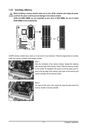
... one direction. DDR3 and DDR2 DIMMs are not compatible to each other or DDR DIMMs. Be sure to the memory module. Step 2: The clips at both ends of the memory, push down on the socket. Follow the steps below to correctly install your fingers on the top edge of ...the socket will snap into the memory socket. Spread the retaining clips at both ends of the memory module. 1-4-2 Installing a Memory Before installing a memory module, make sure to turn off the computer and unplug the power cord from the power outlet...
... one direction. DDR3 and DDR2 DIMMs are not compatible to each other or DDR DIMMs. Be sure to the memory module. Step 2: The clips at both ends of the memory, push down on the socket. Follow the steps below to correctly install your fingers on the top edge of ...the socket will snap into the memory socket. Spread the retaining clips at both ends of the memory module. 1-4-2 Installing a Memory Before installing a memory module, make sure to turn off the computer and unplug the power cord from the power outlet...
Manual
Page 34
... up to a profile. A supervisor password allows you to view the BIOS settings but not to complete. F12: Load CMOS from BIOS If your CPU, memory, etc. Standard CMOS Features Use this task.) Exit Without Saving Abandon all the changes made in BIOS Setup. Set User Password Change...
... up to a profile. A supervisor password allows you to view the BIOS settings but not to complete. F12: Load CMOS from BIOS If your CPU, memory, etc. Standard CMOS Features Use this task.) Exit Without Saving Abandon all the changes made in BIOS Setup. Set User Password Change...
Manual
Page 35
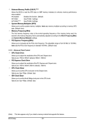
...Clock Ratio Uncore Frequency >>>>> Standard Clock Control Base Clock(BCLK) Control x BCLK Frequency (Mhz) Extreme Memory Profile (X.M.P.) (Note) System Memory Multiplier (SPD) Memory Frequency (Mhz) 1333 PCI Express Frequency (Mhz) >>>>> Advanced Clock Control CPU Clock Drive PCI Express ...] [Press Enter] [Press Enter] [Press Enter] Item Help Menu Level BIOS Version BCLK CPU Frequency Memory Frequency Total Memory Size E7 133.27 MHz 3198.64 MHz 1332.71 MHz 1024 MB CPU Temperature 45oC Vcore DRAM Voltage 1.280V ...
...Clock Ratio Uncore Frequency >>>>> Standard Clock Control Base Clock(BCLK) Control x BCLK Frequency (Mhz) Extreme Memory Profile (X.M.P.) (Note) System Memory Multiplier (SPD) Memory Frequency (Mhz) 1333 PCI Express Frequency (Mhz) >>>>> Advanced Clock Control CPU Clock Drive PCI Express ...] [Press Enter] [Press Enter] [Press Enter] Item Help Menu Level BIOS Version BCLK CPU Frequency Memory Frequency Total Memory Size E7 133.27 MHz 3198.64 MHz 1332.71 MHz 1024 MB CPU Temperature 45oC Vcore DRAM Voltage 1.280V ...
Manual
Page 38
... (SPD) Allows you to set the North Bridge clock prior to the CPU clock. The adjustable range is the normal operating frequency of the memory being used; Options are : 0ps~750ps. (Default: 0ps) IOH Clock Skew Allows you to set the CPU clock prior to the BCLK Frequency(...Mhz) and System Memory Multiplier settings. Options are : 700mV, 800mV, 900mV (default), 1000mV. the second is automatically adjusted according to the Chipset clock. CPU Clock Skew Allows you...
... (SPD) Allows you to set the North Bridge clock prior to the CPU clock. The adjustable range is the normal operating frequency of the memory being used; Options are : 0ps~750ps. (Default: 0ps) IOH Clock Skew Allows you to set the CPU clock prior to the BCLK Frequency(...Mhz) and System Memory Multiplier settings. Options are : 700mV, 800mV, 900mV (default), 1000mV. the second is automatically adjusted according to the Chipset clock. CPU Clock Skew Allows you...

Manual
Page 39
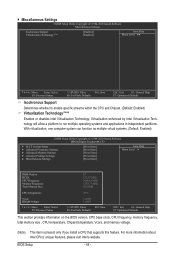
... value based on the SPD data on the XMP memory. Advanced Memory Settings CMOS Setup Utility-Copyright (C) 1984-2010 Award Software Advanced Memory Settings Extreme Memory Profile (X.M.P.) (Note) System Memory Multiplier (SPD) Memory Frequency (Mhz) 1333 Performance Enhance DRAM Timing Selectable ...Value F10: Save F6: Fail-Safe Defaults ESC: Exit F1: General Help F7: Optimized Defaults Extreme Memory Profile (X.M.P.) , (Note) System Memory Multiplier (SPD), Memory Frequency(Mhz) The settings under the same items on the CPU being used. Standard Lets the system...
... value based on the SPD data on the XMP memory. Advanced Memory Settings CMOS Setup Utility-Copyright (C) 1984-2010 Award Software Advanced Memory Settings Extreme Memory Profile (X.M.P.) (Note) System Memory Multiplier (SPD) Memory Frequency (Mhz) 1333 Performance Enhance DRAM Timing Selectable ...Value F10: Save F6: Fail-Safe Defaults ESC: Exit F1: General Help F7: Optimized Defaults Extreme Memory Profile (X.M.P.) , (Note) System Memory Multiplier (SPD), Memory Frequency(Mhz) The settings under the same items on the CPU being used. Standard Lets the system...
Manual
Page 44
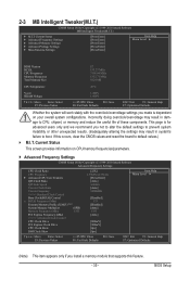
... Enabled) CMOS Setup Utility-Copyright (C) 1984-2010 Award Software MB Intelligent Tweaker(M.I.T.) } M.I.T Current Status } Advanced Frequency Settings } Advanced Memory Settings } Advanced Voltage Settings } Miscellaneous Settings [Press Enter] [Press Enter] [Press Enter] [Press Enter] [Press Enter] Item ...Help Menu Level BIOS Version BCLK CPU Frequency Memory Frequency Total Memory Size E7 133.27 MHz 3198.64 MHz 1332.71 MHz 1024 MB CPU Temperature 45oC Vcore DRAM Voltage 1....
... Enabled) CMOS Setup Utility-Copyright (C) 1984-2010 Award Software MB Intelligent Tweaker(M.I.T.) } M.I.T Current Status } Advanced Frequency Settings } Advanced Memory Settings } Advanced Voltage Settings } Miscellaneous Settings [Press Enter] [Press Enter] [Press Enter] [Press Enter] [Press Enter] Item ...Help Menu Level BIOS Version BCLK CPU Frequency Memory Frequency Total Memory Size E7 133.27 MHz 3198.64 MHz 1332.71 MHz 1024 MB CPU Temperature 45oC Vcore DRAM Voltage 1....
Manual
Page 45
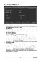
... } IDE Channel 1 Master } IDE Channel 1 Slave } IDE Channel 2 Master } IDE Channel 3 Master [None] [None] [None] [None] [None] [None] Halt On [All, But Keyboard] Base Memory Extended Memory Total Memory 640K 1022M 1024M Move Enter: Select F5: Previous Values +/-/PU/PD: Value F10: Save F6: Fail-Safe Defaults ESC: Exit F1: General Help F7...
... } IDE Channel 1 Master } IDE Channel 1 Slave } IDE Channel 2 Master } IDE Channel 3 Master [None] [None] [None] [None] [None] [None] Halt On [All, But Keyboard] Base Memory Extended Memory Total Memory 640K 1022M 1024M Move Enter: Select F5: Previous Values +/-/PU/PD: Value F10: Save F6: Fail-Safe Defaults ESC: Exit F1: General Help F7...

Manual
Page 46
...fatal error the system boot will not stop for a keyboard error but stop for an error during the POST. Base Memory Also called conventional memory. Total Memory The total amount of extended memory. All, But Keyboard The system boot will stop for any error. Typically, 640 KB will not stop for the MS...-DOS operating system. No Errors The system boot will be reserved for all other errors. (Default) Memory These fields are read-only and are determined by the BIOS POST. Write precompensation cylinder. Extended...
...fatal error the system boot will not stop for a keyboard error but stop for an error during the POST. Base Memory Also called conventional memory. Total Memory The total amount of extended memory. All, But Keyboard The system boot will stop for any error. Typically, 640 KB will not stop for the MS...-DOS operating system. No Errors The system boot will be reserved for all other errors. (Default) Memory These fields are read-only and are determined by the BIOS POST. Write precompensation cylinder. Extended...
Manual
Page 47
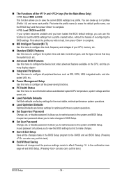
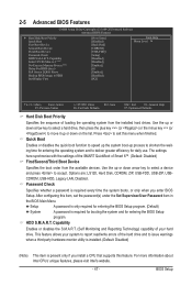
... Disk Boot Priority Quick Boot First Boot Device Second Boot Device Third Boot Device Password Check HDD S.M.A.R.T. Capability Limit CPUID Max. to 3 (Note) No-Execute Memory Protect (Note) Delay For HDD (Secs) Full Screen LOGO Show Backup BIOS Image to speed up the system boot-up or down on the list...
... Disk Boot Priority Quick Boot First Boot Device Second Boot Device Third Boot Device Password Check HDD S.M.A.R.T. Capability Limit CPUID Max. to 3 (Note) No-Execute Memory Protect (Note) Delay For HDD (Secs) Full Screen LOGO Show Backup BIOS Image to speed up the system boot-up or down on the list...

Manual
Page 48
... working with its sup- PCIE x16-2 Sets the PCI Express graphics card on the PCIEX16_1 slot as Windows NT4.0. (Default: Disabled) No-Execute Memory Protect (Note) Enables or disables Intel Execute Disable Bit function. BIOS Setup - 48 - Limit CPUID Max. set a delay time for the ...'s website. to 3 (Note) Allows you install a CPU that supports this item to Enabled for the computer, reducing exposure to display the GIGABYTE Logo at system startup. Set this image file. (Default: Disabled) Init Display First Specifies the first initiation of the monitor display from this item...
... working with its sup- PCIE x16-2 Sets the PCI Express graphics card on the PCIEX16_1 slot as Windows NT4.0. (Default: Disabled) No-Execute Memory Protect (Note) Enables or disables Intel Execute Disable Bit function. BIOS Setup - 48 - Limit CPUID Max. set a delay time for the ...'s website. to 3 (Note) Allows you install a CPU that supports this item to Enabled for the computer, reducing exposure to display the GIGABYTE Logo at system startup. Set this image file. (Default: Disabled) Init Display First Specifies the first initiation of the monitor display from this item...

Manual
Page 53
... to its last known awake state upon the return of power from an AC power loss. Note: To cancel the password, press on the system. Memory The system returns to clear the password settings. Note: you need an ATX power supply providing at least 1A on the +5VSB lead. AC Back...
... to its last known awake state upon the return of power from an AC power loss. Note: To cancel the password, press on the system. Memory The system returns to clear the password settings. Note: you need an ATX power supply providing at least 1A on the +5VSB lead. AC Back...
Manual
Page 63
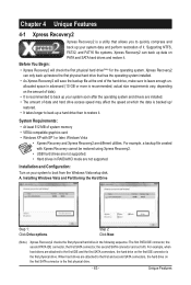
... example, when hard drives are installed. • The amount of data and hard drive access speed may affect the speed at the end of system memory • VESA compatible graphics card • Windows XP with Xpress Recovery cannot be restored using Xpress Recovery2. • USB hard drives are not supported. •...
... example, when hard drives are installed. • The amount of data and hard drive access speed may affect the speed at the end of system memory • VESA compatible graphics card • Windows XP with Xpress Recovery cannot be restored using Xpress Recovery2. • USB hard drives are not supported. •...
Manual
Page 70
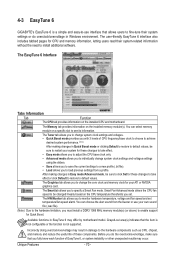
...Memory... be sure to click Set for CPU and memory information, letting users read their system-related information...The CPU tab provides information on the installed memory module(s). The Tuner tab allows you to change.... You can select memory module on the CPU temperature thresholds you must install a DDR3 1066 MHz memory module(s) (or above...Advanced mode allows you to individually change the core clock and memory clock for Quick Boost. Before you to specify a Smart... to the hardware components such as CPU, chipset, and memory and reduce the useful life of CPU frequency/base clock...
...Memory... be sure to click Set for CPU and memory information, letting users read their system-related information...The CPU tab provides information on the installed memory module(s). The Tuner tab allows you to change.... You can select memory module on the CPU temperature thresholds you must install a DDR3 1066 MHz memory module(s) (or above...Advanced mode allows you to individually change the core clock and memory clock for Quick Boost. Before you to specify a Smart... to the hardware components such as CPU, chipset, and memory and reduce the useful life of CPU frequency/base clock...


