Manual
Page 1
GA-X48T-DQ6 LGA775 socket motherboard for Intel® CoreTM processor family/ Intel® Pentium® processor family/Intel® Celeron® processor family User's Manual Rev. 1002 12ME-X48TDQ6-1002R
GA-X48T-DQ6 LGA775 socket motherboard for Intel® CoreTM processor family/ Intel® Pentium® processor family/Intel® Celeron® processor family User's Manual Rev. 1002 12ME-X48TDQ6-1002R
Manual
Page 2
Motherboard GA-X48T-DQ6 Dec. 14, 2007 Motherboard GA-X48T-DQ6 Dec. 14, 2007
Motherboard GA-X48T-DQ6 Dec. 14, 2007 Motherboard GA-X48T-DQ6 Dec. 14, 2007
Manual
Page 3
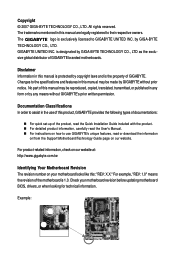
...may be made by GIGA-BYTE TECHNOLOGY CO., LTD. The logo is 1.0. sive global distributor of the motherboard is exclusively licensed to use of this product, GIGABYTE provides the following types of documentations: „ For quick set-up of this manual may be reproduced, ...copied, translated, transmitted, or published in this manual is the property of GIGABYTE. GIGABYTE UNITED INC. The trademarks mentioned in this : "REV: X.X." Check your motherboard looks like this manual are legally registered to the specifications and features in any form or ...
...may be made by GIGA-BYTE TECHNOLOGY CO., LTD. The logo is 1.0. sive global distributor of the motherboard is exclusively licensed to use of this product, GIGABYTE provides the following types of documentations: „ For quick set-up of this manual may be reproduced, ...copied, translated, transmitted, or published in this manual is the property of GIGABYTE. GIGABYTE UNITED INC. The trademarks mentioned in this : "REV: X.X." Check your motherboard looks like this manual are legally registered to the specifications and features in any form or ...
Manual
Page 4
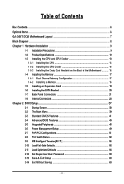
Table of Contents Box Contents ...6 OptionalItems ...6 GA-X48T-DQ6 Motherboard Layout 7 Block Diagram ...8 Chapter 1 Hardware Installation 9 1-1 Installation Precautions 9 1-2 Product Specifications 10 1-3 Installing the CPU and CPU Cooler 13 1-3-1 Installing the CPU 13 1-3-2 Installing the CPU Cooler 15 1-3-3 Installing the Crazy Cool Heatsink on the Back of the Motherboard 16 1-4 Installing the Memory 17 1-4-1 Dual Channel Memory...
Table of Contents Box Contents ...6 OptionalItems ...6 GA-X48T-DQ6 Motherboard Layout 7 Block Diagram ...8 Chapter 1 Hardware Installation 9 1-1 Installation Precautions 9 1-2 Product Specifications 10 1-3 Installing the CPU and CPU Cooler 13 1-3-1 Installing the CPU 13 1-3-2 Installing the CPU Cooler 15 1-3-3 Installing the Crazy Cool Heatsink on the Back of the Motherboard 16 1-4 Installing the Memory 17 1-4-1 Dual Channel Memory...

Manual
Page 6
...COM port cable (Part No. 12CF1-1CM001-32R) LPT port cable (Part No. 12CF1-1LP001-01R) - 6 - The box contents are for reference only. Box Contents GA-X48T-DQ6 motherboard Motherboard driver disk User's Manual Quick Installation Guide Intel® LGA775 CPU Installation Guide One IDE cable and one floppy disk drive cable Four SATA 3Gb.../s cables Two SATA brackets I/O Shield Three screws • The box contents above are subject to change without notice. • The motherboard image is for reference only and the actual items shall depend on product package you obtain.
...COM port cable (Part No. 12CF1-1CM001-32R) LPT port cable (Part No. 12CF1-1LP001-01R) - 6 - The box contents are for reference only. Box Contents GA-X48T-DQ6 motherboard Motherboard driver disk User's Manual Quick Installation Guide Intel® LGA775 CPU Installation Guide One IDE cable and one floppy disk drive cable Four SATA 3Gb.../s cables Two SATA brackets I/O Shield Three screws • The box contents above are subject to change without notice. • The motherboard image is for reference only and the actual items shall depend on product package you obtain.
Manual
Page 7
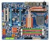
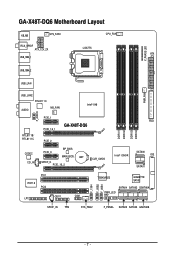
GA-X48T-DQ6 Motherboard Layout KB_MS SYS_FAN1 CPU_FAN RCA_SPDIF ATX_12V_2X LGA775 ATX USB_1394_1 V_PHASE LED USB_1394_2 USB_LAN PWR_FAN USB_LAN2 RTL8111C AUDIO NB_FAN Intel® X48 F_AUDIO RTL8111B/ RTL8111C PCIE_1 PCIE_16_1 GA-X48T-DQ6 PCIE_2 CODEC CD_IN PCIE_3 BP_BIOS MAIN_BIOS BAT SPDIF_O PCIE_16_2 CLR_CMOS FDD DDRIII1 DDRIII2 DDRIII3 DDRIII4 Intel® ICH9R SATAII0 IDE SATAII1 PCI1 IT8718 PCI2 CI COM LPT F_1394 F_USB2 F_USB1 TSB43AB23 GIGABYTE SATA2 SATAII4 SATAII2 GSATAIIA PWR_LED SPDIF_IN TPM SYS_FAN2 F_PANEL SATAII5 SATAII3 GSATAIIB - 7 -
GA-X48T-DQ6 Motherboard Layout KB_MS SYS_FAN1 CPU_FAN RCA_SPDIF ATX_12V_2X LGA775 ATX USB_1394_1 V_PHASE LED USB_1394_2 USB_LAN PWR_FAN USB_LAN2 RTL8111C AUDIO NB_FAN Intel® X48 F_AUDIO RTL8111B/ RTL8111C PCIE_1 PCIE_16_1 GA-X48T-DQ6 PCIE_2 CODEC CD_IN PCIE_3 BP_BIOS MAIN_BIOS BAT SPDIF_O PCIE_16_2 CLR_CMOS FDD DDRIII1 DDRIII2 DDRIII3 DDRIII4 Intel® ICH9R SATAII0 IDE SATAII1 PCI1 IT8718 PCI2 CI COM LPT F_1394 F_USB2 F_USB1 TSB43AB23 GIGABYTE SATA2 SATAII4 SATAII2 GSATAIIA PWR_LED SPDIF_IN TPM SYS_FAN2 F_PANEL SATAII5 SATAII3 GSATAIIB - 7 -
Manual
Page 9
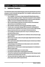
...required for warranty validation. • Always remove the AC power by your hardware components are connected. • To prevent damage to the motherboard, do not have an ESD wrist strap, keep your hands dry and first touch a metal object to eliminate static electricity. • ... to the use of the product, please consult a certified computer technician. - 9 - Chapter 1 Hardware Installation 1-1 Installation Precautions The motherboard contains numerous delicate electronic circuits and components which can lead to damage to system components as well as physical harm to the user. ...
...required for warranty validation. • Always remove the AC power by your hardware components are connected. • To prevent damage to the motherboard, do not have an ESD wrist strap, keep your hands dry and first touch a metal object to eliminate static electricity. • ... to the use of the product, please consult a certified computer technician. - 9 - Chapter 1 Hardware Installation 1-1 Installation Precautions The motherboard contains numerous delicate electronic circuits and components which can lead to damage to system components as well as physical harm to the user. ...
Manual
Page 10
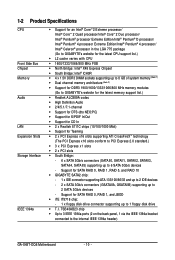
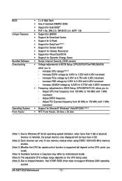
...Note 1) Š Dual channel memory architecture (Note 2) Š Support for DDR3 1900/1600/1333/1066/800 MHz memory modules (Go to GIGABYTE's website for the latest memory support list.) Š Realtek ALC889A codec Š High Definition Audio Š 2/4/5.1/7.1-channel Š Support for... Bridge: - 6 x SATA 3Gb/s connectors (SATAII0, SATAII1, SATAII2, SATAII3, SATAII4, SATAII5) supporting up to the internal IEEE 1394a header) GA-X48T-DQ6 Motherboard - 10 - TSB43AB23 chip Š Up to 3 IEEE 1394a ports (2 on the back panel, 1 via the IEEE 1394a bracket connected to 6 SATA 3Gb/s devices...
...Note 1) Š Dual channel memory architecture (Note 2) Š Support for DDR3 1900/1600/1333/1066/800 MHz memory modules (Go to GIGABYTE's website for the latest memory support list.) Š Realtek ALC889A codec Š High Definition Audio Š 2/4/5.1/7.1-channel Š Support for... Bridge: - 6 x SATA 3Gb/s connectors (SATAII0, SATAII1, SATAII2, SATAII3, SATAII4, SATAII5) supporting up to the internal IEEE 1394a header) GA-X48T-DQ6 Motherboard - 10 - TSB43AB23 chip Š Up to 3 IEEE 1394a ports (2 on the back panel, 1 via the IEEE 1394a bracket connected to 6 SATA 3Gb/s devices...
Manual
Page 12
...0.05V to 0.75V with 0.05V increment - Increase PCIe voltage by 0.05V to 1.55V with 1 MHz increment - Increase FSB voltage by motherboard model. (Note 5) The adjustable CPU voltage range depends on the CPU being used. (Note 6) Due to chipset limitation, Intel ICH9R RAID ...to: - Increase CPU voltage (Note 5) - Adjust PCI Express frequency from 100 MHz to 700 MHz with 0.05V increment - Adjust DDR3 frequency - GA-X48T-DQ6 Motherboard - 12 - BIOS Unique Features Bundled Software Overclocking Operating System Form Factor Š 2 x 8 Mbit flash Š Use of licensed AWARD BIOS ...
...0.05V to 0.75V with 0.05V increment - Increase PCIe voltage by 0.05V to 1.55V with 1 MHz increment - Increase FSB voltage by motherboard model. (Note 5) The adjustable CPU voltage range depends on the CPU being used. (Note 6) Due to chipset limitation, Intel ICH9R RAID ...to: - Increase CPU voltage (Note 5) - Adjust PCI Express frequency from 100 MHz to 700 MHz with 0.05V increment - Adjust DDR3 frequency - GA-X48T-DQ6 Motherboard - 12 - BIOS Unique Features Bundled Software Overclocking Operating System Form Factor Š 2 x 8 Mbit flash Š Use of licensed AWARD BIOS ...
Manual
Page 13
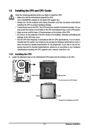
LGA775 CPU Socket Alignment Key LGA 775 CPU Alignment Key Pin One Corner of the CPU. mended that the motherboard supports the CPU. (Go to GIGABYTE's website for the peripherals. The CPU cannot be set the frequency beyond hardware specifications since it does not meet the standard requirements for ...; Locate the pin one of the CPU Socket Notch Notch Triangle Pin One Marking on the CPU - 13 - Locate the alignment keys on the motherboard CPU socket and the notches on the computer if the CPU cooler is not recom- It is not installed, otherwise overheating and damage of the...
LGA775 CPU Socket Alignment Key LGA 775 CPU Alignment Key Pin One Corner of the CPU. mended that the motherboard supports the CPU. (Go to GIGABYTE's website for the peripherals. The CPU cannot be set the frequency beyond hardware specifications since it does not meet the standard requirements for ...; Locate the pin one of the CPU Socket Notch Notch Triangle Pin One Marking on the CPU - 13 - Locate the alignment keys on the motherboard CPU socket and the notches on the computer if the CPU cooler is not recom- It is not installed, otherwise overheating and damage of the...

Manual
Page 14
... and unplug the power cord from the power outlet to prevent damage to correctly install the CPU into the motherboard CPU socket. CPU Socket Lever Step 1: Completely raise the CPU socket lever. GA-X48T-DQ6 Motherboard - 14 - Step 3: Lift the metal load plate on the CPU socket. Follow the steps below to the CPU. Step...
... and unplug the power cord from the power outlet to prevent damage to correctly install the CPU into the motherboard CPU socket. CPU Socket Lever Step 1: Completely raise the CPU socket lever. GA-X48T-DQ6 Motherboard - 14 - Step 3: Lift the metal load plate on the CPU socket. Follow the steps below to the CPU. Step...
Manual
Page 15
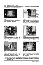
.... Step 4: You should hear a "click" when pushing down on the male push pin. (Turning the push pin along the direction of the motherboard. Step 6: Finally, attach the power connector of the installed CPU. Hardware Installation If the push pin is inserted as the example cooler.) Step 1:...manual for instructions on installing the cooler.) Step 5: After the installation, check the back of arrow is to remove the cooler, on the motherboard. Push down each push pin. Inadequately removing the CPU cooler may adhere to install.) Step 3: Place the cooler atop the CPU, aligning ...
.... Step 4: You should hear a "click" when pushing down on the male push pin. (Turning the push pin along the direction of the motherboard. Step 6: Finally, attach the power connector of the installed CPU. Hardware Installation If the push pin is inserted as the example cooler.) Step 1:...manual for instructions on installing the cooler.) Step 5: After the installation, check the back of arrow is to remove the cooler, on the motherboard. Push down each push pin. Inadequately removing the CPU cooler may adhere to install.) Step 3: Place the cooler atop the CPU, aligning ...
Manual
Page 16
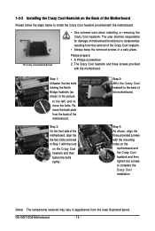
... heatsink. • Always keep the removed screws in a safe place. The Crazy Cool heatsink and three screws provided with the motherboard. Remove the back plate from the removal of the motherboard. Please prepare: 1. GA-X48T-DQ6 Motherboard - 16 - The Crazy Cool Heatsink/Screws • Use extreme care when installing or removing the Crazy Cool heatsink. 1-3-3 Installing...
... heatsink. • Always keep the removed screws in a safe place. The Crazy Cool heatsink and three screws provided with the motherboard. Remove the back plate from the removal of the motherboard. Please prepare: 1. GA-X48T-DQ6 Motherboard - 16 - The Crazy Cool Heatsink/Screws • Use extreme care when installing or removing the Crazy Cool heatsink. 1-3-3 Installing...

Manual
Page 17
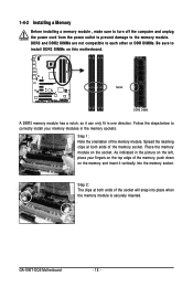
... DS/SS - - The four DDR3 memory sockets are unable to insert the memory, switch the direction. 1-4-1 Dual Channel Memory Configuration This motherboard provides four DDR3 memory sockets and supports Dual Channel Technology. A memory module can only fit one direction. Enabling Dual Channel memory mode will ...and chips be used and installed in the same colored DDR3 sockets for optimum performance. • Each channel can be used. (Go to GIGABYTE's website for the latest memory support list.) • Always turn off the computer and unplug the power cord from the power outlet before...
... DS/SS - - The four DDR3 memory sockets are unable to insert the memory, switch the direction. 1-4-1 Dual Channel Memory Configuration This motherboard provides four DDR3 memory sockets and supports Dual Channel Technology. A memory module can only fit one direction. Enabling Dual Channel memory mode will ...and chips be used and installed in the same colored DDR3 sockets for optimum performance. • Each channel can be used. (Go to GIGABYTE's website for the latest memory support list.) • Always turn off the computer and unplug the power cord from the power outlet before...
Manual
Page 18
Spread the retaining clips at both ends of the memory module. GA-X48T-DQ6 Motherboard - 18 - Notch DDR3 DIMM A DDR3 memory module has a notch, so it vertically into place when the memory module is securely inserted. Follow the steps below ... , make sure to turn off the computer and unplug the power cord from the power outlet to prevent damage to install DDR3 DIMMs on this motherboard.
Spread the retaining clips at both ends of the memory module. GA-X48T-DQ6 Motherboard - 18 - Notch DDR3 DIMM A DDR3 memory module has a notch, so it vertically into place when the memory module is securely inserted. Follow the steps below ... , make sure to turn off the computer and unplug the power cord from the power outlet to prevent damage to install DDR3 DIMMs on this motherboard.
Manual
Page 19
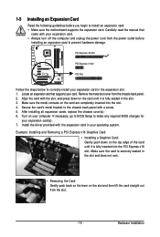
... provided with your card. Remove the metal slot cover from the power outlet before you begin to install an expansion card: • Make sure the motherboard supports the expansion card. Make sure the card is securely seated in your expansion card in the slot. 3. Secure the card's metal bracket to the...
... provided with your card. Remove the metal slot cover from the power outlet before you begin to install an expansion card: • Make sure the motherboard supports the expansion card. Make sure the card is securely seated in your expansion card in the slot. 3. Secure the card's metal bracket to the...
Manual
Page 20
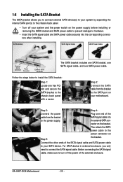
...: Step 1: Locate one SATA power cable. the external SATA con- Connect the other ends of the SATA signal cable and SATA power cable to your motherboard. GA-X48T-DQ6 Motherboard - 20 - SATA Bracket SATA Signal Cable SATA Power Cable External SATA Connector Power Connector External SATA Connector The SATA bracket includes one SATA bracket, one...
...: Step 1: Locate one SATA power cable. the external SATA con- Connect the other ends of the SATA signal cable and SATA power cable to your motherboard. GA-X48T-DQ6 Motherboard - 20 - SATA Bracket SATA Signal Cable SATA Power Cable External SATA Connector Power Connector External SATA Connector The SATA bracket includes one SATA bracket, one...
Manual
Page 21
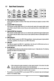
... connect a PS/2 mouse and the lower port (purple) to a back panel connector, first remove the cable from your device and then remove it from the motherboard. • When removing the cable, pull it side to side to 1 Gbps data rate. Connection/ Speed LED Activity LED LAN Port Connection/Speed LED: State...
... connect a PS/2 mouse and the lower port (purple) to a back panel connector, first remove the cable from your device and then remove it from the motherboard. • When removing the cable, pull it side to side to 1 Gbps data rate. Connection/ Speed LED Activity LED LAN Port Connection/Speed LED: State...

Manual
Page 22
.... Mic In Jack (Pink) The default Mic in a 4/5.1/7.1-channel audio configuration. Only microphones still MUST be used to connect front speakers in a 5.1/7.1-channel audio configuration. GA-X48T-DQ6 Motherboard - 22 - Line In Jack (Blue) The default line in jack ( ). Use this audio jack for line in Chapter 5, "Configuring 2/4/5.1/7.1-Channel Audio." Refer to the instructions...
.... Mic In Jack (Pink) The default Mic in a 4/5.1/7.1-channel audio configuration. Only microphones still MUST be used to connect front speakers in a 5.1/7.1-channel audio configuration. GA-X48T-DQ6 Motherboard - 22 - Line In Jack (Blue) The default line in jack ( ). Use this audio jack for line in Chapter 5, "Configuring 2/4/5.1/7.1-Channel Audio." Refer to the instructions...
Manual
Page 23
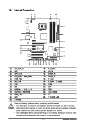
...) F_1394 19) F_USB1 / F_USB2 20) COM 21) LPT 22) TPM 23) CLR_CMOS 24) CI 25) V_PHASE LED Read the following guidelines before turning on the motherboard. - 23 - Hardware Installation
...) F_1394 19) F_USB1 / F_USB2 20) COM 21) LPT 22) TPM 23) CLR_CMOS 24) CI 25) V_PHASE LED Read the following guidelines before turning on the motherboard. - 23 - Hardware Installation


