Manual
Page 4
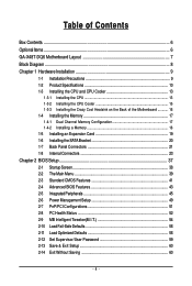
... Cool Heatsink on the Back of the Motherboard 16 1-4 Installing the Memory 17 1-4-1 Dual Channel Memory Configuration 17 1-4-2 Installing a Memory 18 1-5 Installing an Expansion Card 19 1-6 Installing the SATA Bracket 20 1-7 Back Panel Connectors 21 1-8 Internal Connectors 23 Chapter 2 BIOS Setup 37 2-1 Startup Screen 38 2-2 The Main Menu 39 2-3 Standard CMOS Features 41 2-4 Advanced BIOS Features 43 2-5 IntegratedPeripherals 45 2-6 Power Management Setup 49 2-7 PnP/PCI Configurations 51 2-8 PC Health Status 52 2-9 MB Intelligent Tweaker(M.I.T 54 2-10 Load Fail-Safe Defaults...
... Cool Heatsink on the Back of the Motherboard 16 1-4 Installing the Memory 17 1-4-1 Dual Channel Memory Configuration 17 1-4-2 Installing a Memory 18 1-5 Installing an Expansion Card 19 1-6 Installing the SATA Bracket 20 1-7 Back Panel Connectors 21 1-8 Internal Connectors 23 Chapter 2 BIOS Setup 37 2-1 Startup Screen 38 2-2 The Main Menu 39 2-3 Standard CMOS Features 41 2-4 Advanced BIOS Features 43 2-5 IntegratedPeripherals 45 2-6 Power Management Setup 49 2-7 PnP/PCI Configurations 51 2-8 PC Health Status 52 2-9 MB Intelligent Tweaker(M.I.T 54 2-10 Load Fail-Safe Defaults...
Manual
Page 10
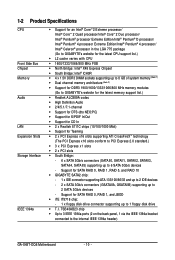
... IDE devices - 2 x SATA 3Gb/s connectors (GSATAIIA, GSATAIIB) supporting up to 2 SATA 3Gb/s devices - Support for SATA RAID 0, RAID 1, and JBOD Š iTE IT8718 chip: - 1 x floppy disk drive connector supporting up to 6 SATA 3Gb/s devices - TSB43AB23 chip Š Up to 3 IEEE 1394a ports (2 on the back panel, 1 via the IEEE 1394a bracket connected to the internal IEEE 1394a header) GA-X48T-DQ6 Motherboard - 10 - 1-2 Product Specifications CPU Front Side Bus Chipset Memory Audio LAN Expansion Slots Storage Interface IEEE 1394a Š Support for an Intel® CoreTM 2 Extreme processor...
... IDE devices - 2 x SATA 3Gb/s connectors (GSATAIIA, GSATAIIB) supporting up to 2 SATA 3Gb/s devices - Support for SATA RAID 0, RAID 1, and JBOD Š iTE IT8718 chip: - 1 x floppy disk drive connector supporting up to 6 SATA 3Gb/s devices - TSB43AB23 chip Š Up to 3 IEEE 1394a ports (2 on the back panel, 1 via the IEEE 1394a bracket connected to the internal IEEE 1394a header) GA-X48T-DQ6 Motherboard - 10 - 1-2 Product Specifications CPU Front Side Bus Chipset Memory Audio LAN Expansion Slots Storage Interface IEEE 1394a Š Support for an Intel® CoreTM 2 Extreme processor...
Manual
Page 12
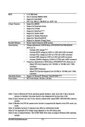
... fit one memory module when using DDR3 1900/1600 MHz memory module. (Note 3) Whether the CPU fan speed control function is supported will depend on the CPU cooler you install. (Note 4) Available functions in Easytune may differ by motherboard model. (Note 5) The adjustable CPU voltage range depends on the CPU being used. (Note 6) Due to chipset limitation, Intel ICH9R RAID driver does not support Windows 2000 operating system. Adjust CPU host frequency from...
... fit one memory module when using DDR3 1900/1600 MHz memory module. (Note 3) Whether the CPU fan speed control function is supported will depend on the CPU cooler you install. (Note 4) Available functions in Easytune may differ by motherboard model. (Note 5) The adjustable CPU voltage range depends on the CPU being used. (Note 6) Due to chipset limitation, Intel ICH9R RAID driver does not support Windows 2000 operating system. Adjust CPU host frequency from...
Manual
Page 25
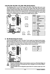
... Installation Most fan headers possess a foolproof insertion design. When connecting a fan cable, be installed inside the chassis. 1 CPU_FAN 1 SYS_FAN2 CPU_FAN: Pin No. 1 2 3 4 SYS_FAN2: Pin No. 1 2 3 4 Definition GND +12V / Speed Control Sense Speed Control Definition GND +12V / Speed Control Sense Reserve 1 SYS_FAN1 1 PWR_FAN SYS_FAN1/PWR_FAN: Pin No. The fan header has a foolproof insertion design. The motherboard supports CPU fan speed control, which requires the use of a CPU fan with color-coded power connector wires. When connecting a fan cable, be sure to the CPU...
... Installation Most fan headers possess a foolproof insertion design. When connecting a fan cable, be installed inside the chassis. 1 CPU_FAN 1 SYS_FAN2 CPU_FAN: Pin No. 1 2 3 4 SYS_FAN2: Pin No. 1 2 3 4 Definition GND +12V / Speed Control Sense Speed Control Definition GND +12V / Speed Control Sense Reserve 1 SYS_FAN1 1 PWR_FAN SYS_FAN1/PWR_FAN: Pin No. The fan header has a foolproof insertion design. The motherboard supports CPU fan speed control, which requires the use of a CPU fan with color-coded power connector wires. When connecting a fan cable, be sure to the CPU...

Manual
Page 43
...boot order from the installed hard drives. Capability Enables or disables the S.M.A.R.T. (Self Monitoring and Reporting Technology) capability of your system to exit this item, set the password(s) under the Set Supervisor/User Password item in the BIOS Main Menu. 2-4 Advanced BIOS Features CMOS Setup Utility-Copyright (C) 1984-2007 Award Software Advanced BIOS Features ` Hard Disk Boot Priority First Boot Device [Press Enter] [Floppy] Item Help Menu Level` Second Boot Device Third Boot Device Password Check [Hard Disk] [CDROM] [Setup] HDD S.M.A.R.T. Password...
...boot order from the installed hard drives. Capability Enables or disables the S.M.A.R.T. (Self Monitoring and Reporting Technology) capability of your system to exit this item, set the password(s) under the Set Supervisor/User Password item in the BIOS Main Menu. 2-4 Advanced BIOS Features CMOS Setup Utility-Copyright (C) 1984-2007 Award Software Advanced BIOS Features ` Hard Disk Boot Priority First Boot Device [Press Enter] [Floppy] Item Help Menu Level` Second Boot Device Third Boot Device Password Check [Hard Disk] [CDROM] [Setup] HDD S.M.A.R.T. Password...
Manual
Page 44
... heat production. (Default: Enabled) Virtualization Technology (Note) Enables or disables Intel® Virtualization Technology. Depending on the first PCIe x16 slot (PCIE_16_1) as Windows NT4.0. (Default: Disabled) No-Execute Memory Protect (Note) Enables or disables Intel® Execute Disable Bit function. set this item to Enabled for Windows XP operating system; Virtualization enhanced by Intel® Virtualization Technology will be reduced when the CPU is present only if you install a CPU that supports this feature. GA-X48T-DQ6 Motherboard - 44 - For...
... heat production. (Default: Enabled) Virtualization Technology (Note) Enables or disables Intel® Virtualization Technology. Depending on the first PCIe x16 slot (PCIE_16_1) as Windows NT4.0. (Default: Disabled) No-Execute Memory Protect (Note) Enables or disables Intel® Execute Disable Bit function. set this item to Enabled for Windows XP operating system; Virtualization enhanced by Intel® Virtualization Technology will be reduced when the CPU is present only if you install a CPU that supports this feature. GA-X48T-DQ6 Motherboard - 44 - For...
Manual
Page 45
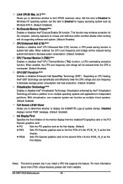
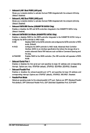
... Setup Utility-Copyright (C) 1984-2007 Award Software Integrated Peripherals SATA RAID/AHCI Mode SATA Port0-3 Native Mode USB Controller USB 2.0 Controller USB Keyboard Support USB Mouse Support Legacy USB storage detect Azalia Codec Onboard H/W 1394 Onboard H/W LAN1 Onboard H/W LAN2 ` SMART LAN1 ` SMART LAN2 Onboard LAN1 Boot ROM Onboard LAN2 Boot ROM Onboard SATA/IDE Device Onboard SATA/IDE Ctrl Mode Onboard Serial Port 1 Onboard Parallel Port [Disabled] [Disabled] [Enabled] [Enabled] [Disabled] [Disabled] [Enabled] [Auto] [Enabled] [Enabled] [Enabled] [Press Enter] [Press Enter] [Disabled...
... Setup Utility-Copyright (C) 1984-2007 Award Software Integrated Peripherals SATA RAID/AHCI Mode SATA Port0-3 Native Mode USB Controller USB 2.0 Controller USB Keyboard Support USB Mouse Support Legacy USB storage detect Azalia Codec Onboard H/W 1394 Onboard H/W LAN1 Onboard H/W LAN2 ` SMART LAN1 ` SMART LAN2 Onboard LAN1 Boot ROM Onboard LAN2 Boot ROM Onboard SATA/IDE Device Onboard SATA/IDE Ctrl Mode Onboard Serial Port 1 Onboard Parallel Port [Disabled] [Disabled] [Enabled] [Enabled] [Disabled] [Disabled] [Enabled] [Auto] [Enabled] [Enabled] [Enabled] [Press Enter] [Press Enter] [Disabled...
Manual
Page 48
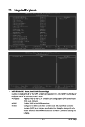
..., 3BC/IRQ7, Disabled. Options are : Auto, 3F8/IRQ4 (default), 2F8/IRQ3, 3E8/IRQ4, 2E8/IRQ3, Disabled. GA-X48T-DQ6 Motherboard - 48 - IDE Disables RAID for the SATA controller integrated in the GIGABYTE SATA 2 chip or configures the SATA controller to AHCI mode. Onboard Parallel Port Enables or disables the onboard parallel port (LPT) and specifies its base I /O address and corresponding interrupt. Options are: SPP (Standard Parallel Port)(default), EPP (Enhanced Parallel Port), ECP (Extended Capabilities Port), ECP+EPP. Advanced Host Controller Interface (AHCI) is an...
..., 3BC/IRQ7, Disabled. Options are : Auto, 3F8/IRQ4 (default), 2F8/IRQ3, 3E8/IRQ4, 2E8/IRQ3, Disabled. GA-X48T-DQ6 Motherboard - 48 - IDE Disables RAID for the SATA controller integrated in the GIGABYTE SATA 2 chip or configures the SATA controller to AHCI mode. Onboard Parallel Port Enables or disables the onboard parallel port (LPT) and specifies its base I /O address and corresponding interrupt. Options are: SPP (Standard Parallel Port)(default), EPP (Enhanced Parallel Port), ECP (Extended Capabilities Port), ECP+EPP. Advanced Host Controller Interface (AHCI) is an...
Manual
Page 53
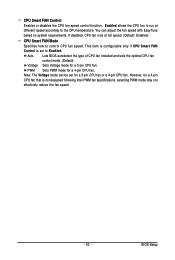
CPU Smart FAN Control Enables or disables the CPU fan speed control function. If disabled, CPU fan runs at different speed according to the CPU temperature. Note: The Voltage mode can adjust the fan speed with EasyTune based on system requirements. This item is configurable only if CPU Smart FAN Control is not designed following Intel PWM fan specifications, selecting PWM mode may not effectively reduce the fan speed. - 53 - However, for a 4-pin CPU fan that is set for a 3-pin CPU fan or a 4-pin CPU fan. BIOS Setup Auto Lets BIOS autodetect the type of CPU fan installed ...
CPU Smart FAN Control Enables or disables the CPU fan speed control function. If disabled, CPU fan runs at different speed according to the CPU temperature. Note: The Voltage mode can adjust the fan speed with EasyTune based on system requirements. This item is configurable only if CPU Smart FAN Control is not designed following Intel PWM fan specifications, selecting PWM mode may not effectively reduce the fan speed. - 53 - However, for a 4-pin CPU fan that is set for a 3-pin CPU fan or a 4-pin CPU fan. BIOS Setup Auto Lets BIOS autodetect the type of CPU fan installed ...
Manual
Page 55
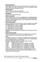
..., or clear the CMOS values to reset the board to default values. (Default: Disabled) CPU Host Frequency (Mhz) Allows you to manually set in accordance with unlocked clock ratio is highly dependent on CPU loading. As stability is installed. Auto allows the BIOS to 150 MHz. CPU Clock Ratio (Note) Allows you install a CPU that the CPU frequency be configurable. Enabled will allow for the installed CPU. For a 1066 MHz FSB CPU, set the R.G.B. Disabled Disables the use of C.I.A.2. (Default) Cruise Increases CPU frequency by 5% or...
..., or clear the CMOS values to reset the board to default values. (Default: Disabled) CPU Host Frequency (Mhz) Allows you to manually set in accordance with unlocked clock ratio is highly dependent on CPU loading. As stability is installed. Auto allows the BIOS to 150 MHz. CPU Clock Ratio (Note) Allows you install a CPU that the CPU frequency be configurable. Enabled will allow for the installed CPU. For a 1066 MHz FSB CPU, set the R.G.B. Disabled Disables the use of C.I.A.2. (Default) Cruise Increases CPU frequency by 5% or...
Manual
Page 60
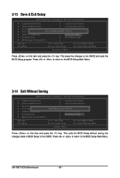
... key. This saves the changes to the CMOS. This exits the BIOS Setup without saving the changes made in BIOS Setup to the CMOS and exits the BIOS Setup program. Press or to return to the BIOS Setup Main Menu. GA-X48T-DQ6 Motherboard - 60 - 2-13 Save & Exit Setup CMOS Setup Utility-Copyright (C) 1984-2007 Award Software ` Standard CMOS Features Load Fail-Safe Defaults ` Advanced BIOS Features Load Optimized Defaults ` Integrated Peripherals Set Supervisor Password ` Power Management Setup Save to CMOS and EXIT (SYe/tNU)?seYr Password ` PnP/PCI Configurations...
... key. This saves the changes to the CMOS. This exits the BIOS Setup without saving the changes made in BIOS Setup to the CMOS and exits the BIOS Setup program. Press or to return to the BIOS Setup Main Menu. GA-X48T-DQ6 Motherboard - 60 - 2-13 Save & Exit Setup CMOS Setup Utility-Copyright (C) 1984-2007 Award Software ` Standard CMOS Features Load Fail-Safe Defaults ` Advanced BIOS Features Load Optimized Defaults ` Integrated Peripherals Set Supervisor Password ` Power Management Setup Save to CMOS and EXIT (SYe/tNU)?seYr Password ` PnP/PCI Configurations...
Manual
Page 71
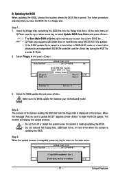
... BIOS. Q-Flash Utility v2.05 Flash Type/Size SST 25VF080B 1M EnteFr l:oRppuyn A HDD 0-0 Keep DMI Data Enable Update BIOS from the floppy disk is displayed on the screen. When the message "Are you to save the BIOS file to update BIOS?" Step 3: When the update process is saved to a hard drive in RAID/AHCI mode or a hard drive attached to an independent IDE/SATA controller, use the up or down arrow key to select Update BIOS from Drive and press . • The Save Main BIOS...
... BIOS. Q-Flash Utility v2.05 Flash Type/Size SST 25VF080B 1M EnteFr l:oRppuyn A HDD 0-0 Keep DMI Data Enable Update BIOS from the floppy disk is displayed on the screen. When the message "Are you to save the BIOS file to update BIOS?" Step 3: When the update process is saved to a hard drive in RAID/AHCI mode or a hard drive attached to an independent IDE/SATA controller, use the up or down arrow key to select Update BIOS from Drive and press . • The Save Main BIOS...
Manual
Page 79
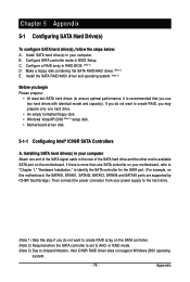
... that you may prepare only one SATA controller on this motherboard, the SATAII0, SATAII1, SATAII2, SATAII3, SATAII4 and SATAII5 ports are supported by ICH9R Southbridge.) Then connect the power connector from your computer. Configure SATA controller mode in your power supply to the hard drive. (Note 1) Skip this step if you do not want to create RAID, you use two hard drives with identical model and capacity). Make a floppy disk containing the SATA RAID/AHCI driver. (Note 2) E.
... that you may prepare only one SATA controller on this motherboard, the SATAII0, SATAII1, SATAII2, SATAII3, SATAII4 and SATAII5 ports are supported by ICH9R Southbridge.) Then connect the power connector from your computer. Configure SATA controller mode in your power supply to the hard drive. (Note 1) Skip this step if you do not want to create RAID, you use two hard drives with identical model and capacity). Make a floppy disk containing the SATA RAID/AHCI driver. (Note 2) E.
Manual
Page 85
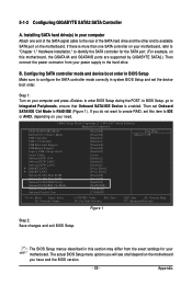
... the BIOS version. - 85 - CMOS Setup Utility-Copyright (C) 1984-2007 Award Software Integrated Peripherals SATA RAID/AHCI Mode SATA Port0-3 Native Mode USB Controller USB 2.0 Controller USB Keyboard Support USB Mouse Support Legacy USB storage detect Azalia Codec Onboard H/W 1394 Onboard H/W LAN1 Onboard H/W LAN2 ` SMART LAN1 ` SMART LAN2 Onboard LAN1 Boot ROM Onboard LAN2 Boot ROM Onboard SATA/IDE Device Onboard SATA/IDE Ctrl Mode Onboard Serial Port 1 Onboard Parallel Port [Disabled] [Disabled] [Enabled] [Enabled] [Disabled] [Disabled] [Enabled] [Auto] [Enabled] [Enabled] [Enabled] [Press...
... the BIOS version. - 85 - CMOS Setup Utility-Copyright (C) 1984-2007 Award Software Integrated Peripherals SATA RAID/AHCI Mode SATA Port0-3 Native Mode USB Controller USB 2.0 Controller USB Keyboard Support USB Mouse Support Legacy USB storage detect Azalia Codec Onboard H/W 1394 Onboard H/W LAN1 Onboard H/W LAN2 ` SMART LAN1 ` SMART LAN2 Onboard LAN1 Boot ROM Onboard LAN2 Boot ROM Onboard SATA/IDE Device Onboard SATA/IDE Ctrl Mode Onboard Serial Port 1 Onboard Parallel Port [Disabled] [Disabled] [Enabled] [Enabled] [Disabled] [Disabled] [Enabled] [Auto] [Enabled] [Enabled] [Enabled] [Press...
Manual
Page 86
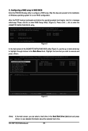
...: ST3120026AS Capacity 120 GB 120 GB Type/Status Non-RAID Non-RAID [ RAID Disk Drive List ] [IJTAB]-Switch Window [KL]-Select ITEM [ENTER]-Action Figure 3 [ESC]-Exit (Note) In the main screen, you wish to configure a RAID array. GIGABYTE Technology Corp. http://www.gigabyte.com.tw HDD0 : HDD1 : ST3120026AS ST3120026AS 120 GB Non-RAID 120 GB Non-RAID ODD0 : DVDROM GO-D1600B Press to enter the GIGABYTE SATA2 RAID BIOS utility. GA-X48T-DQ6 Motherboard - 86 - Press + to enter RAID Setup Utility ... C.
...: ST3120026AS Capacity 120 GB 120 GB Type/Status Non-RAID Non-RAID [ RAID Disk Drive List ] [IJTAB]-Switch Window [KL]-Select ITEM [ENTER]-Action Figure 3 [ESC]-Exit (Note) In the main screen, you wish to configure a RAID array. GIGABYTE Technology Corp. http://www.gigabyte.com.tw HDD0 : HDD1 : ST3120026AS ST3120026AS 120 GB Non-RAID 120 GB Non-RAID ODD0 : DVDROM GO-D1600B Press to enter the GIGABYTE SATA2 RAID BIOS utility. GA-X48T-DQ6 Motherboard - 86 - Press + to enter RAID Setup Utility ... C.
Manual
Page 91
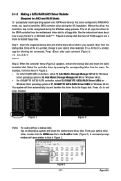
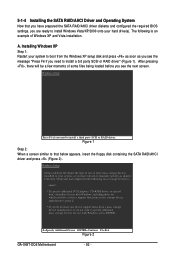
... A:\> prompt, change to install the SATA controller driver during the Windows setup process. Figure 1 Figure 2 (Note) For users without a startup disk: Use an alternative system and insert the motherboard driver disk. At the D:\> prompt, type the following two commands. Your system will open similar to a floppy disk. Step 1: Insert the prepared startup disk and motherboard driver disk in MS-DOS mode(Note). Appendix 5-1-3 Making a SATA RAID/AHCI Driver Diskette (Required for AHCI and RAID Mode) To successfully install operating...
... A:\> prompt, change to install the SATA controller driver during the Windows setup process. Figure 1 Figure 2 (Note) For users without a startup disk: Use an alternative system and insert the motherboard driver disk. At the D:\> prompt, type the following two commands. Your system will open similar to a floppy disk. Step 1: Insert the prepared startup disk and motherboard driver disk in MS-DOS mode(Note). Appendix 5-1-3 Making a SATA RAID/AHCI Driver Diskette (Required for AHCI and RAID Mode) To successfully install operating...
Manual
Page 92
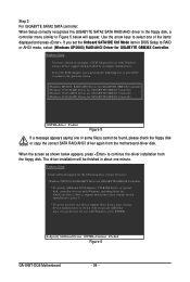
... screen. Windows Setup Setup could not determine the type of one or more mass storage devices installed in your hard drive(s). S=Specify Additional Device ENTER=Continue F3=Exit Figure 2 GA-X48T-DQ6 Motherboard - 92 - A. After pressing , there will load support for the following is an example of some files being loaded before you need to manually specify an adapter. The following mass storage devices(s) * To specify additional SCSI adapters, CD-ROM drives, or special disk controllers for use...
... screen. Windows Setup Setup could not determine the type of one or more mass storage devices installed in your hard drive(s). S=Specify Additional Device ENTER=Continue F3=Exit Figure 2 GA-X48T-DQ6 Motherboard - 92 - A. After pressing , there will load support for the following is an example of some files being loaded before you need to manually specify an adapter. The following mass storage devices(s) * To specify additional SCSI adapters, CD-ROM drives, or special disk controllers for use...
Manual
Page 94
...) RAID/AHCI Driver for GIGABYTE GBB36X Controller * To specify additional SCSI adapters, CD-ROM drives, or special disk controllers for use with Windows, including those for which you have a device support disk from a mass storage device manufacturer, press S. * If you set the Onboard SATA/IDE Ctrl Mode item in BIOS Setup to RAID or AHCI mode, select (Windows XP/2003) RAID/AHCI Driver for use with Windows, using a device support disk provided by an adapter manufacturer. Windows Setup You have chosen to configure a SCSI Adapter for GIGABYTE GBB36X Controller. Use the arrow keys...
...) RAID/AHCI Driver for GIGABYTE GBB36X Controller * To specify additional SCSI adapters, CD-ROM drives, or special disk controllers for use with Windows, including those for which you have a device support disk from a mass storage device manufacturer, press S. * If you set the Onboard SATA/IDE Ctrl Mode item in BIOS Setup to RAID or AHCI mode, select (Windows XP/2003) RAID/AHCI Driver for use with Windows, using a device support disk provided by an adapter manufacturer. Windows Setup You have chosen to configure a SCSI Adapter for GIGABYTE GBB36X Controller. Use the arrow keys...
Manual
Page 105
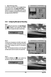
... S/PDIF OUT. 5-2-4 Configuring Microphone Recording Step 1: After installing the audio driver, the Audio Manager icon will appear in your system tray and click it to access the Audio Control Panel. Then configure the jack for microphone functionality. Doubleclick the icon to open the volume control panel. - 105 - Digital PCM Output Setup: In the Audio Control Panel, click the Audio I/O tab. Appendix 4. In the upper left list, click Digital...
... S/PDIF OUT. 5-2-4 Configuring Microphone Recording Step 1: After installing the audio driver, the Audio Manager icon will appear in your system tray and click it to access the Audio Control Panel. Then configure the jack for microphone functionality. Doubleclick the icon to open the volume control panel. - 105 - Digital PCM Output Setup: In the Audio Control Panel, click the Audio I/O tab. Appendix 4. In the upper left list, click Digital...
Manual
Page 110
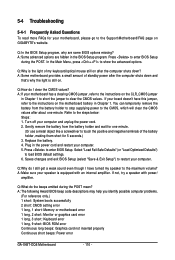
... to the Support\Motherboard\FAQ page on after the computer shuts down ? A: The following Award BIOS beep code descriptions may help you identify possible computer problems. (For reference only.) 1 short: System boots successfully 2 short: CMOS setting error 1 long, 1 short: Memory or motherboard error 1 long, 2 short: Monitor or graphics card error 1 long, 3 short: Keyboard error 1 long, 9 short: BIOS ROM error Continuous long beeps: Graphics card not inserted properly Continuous short beeps: Power error GA-X48T-DQ6 Motherboard - 110 - 5-4 Troubleshooting 5-4-1 Frequently Asked...
... to the Support\Motherboard\FAQ page on after the computer shuts down ? A: The following Award BIOS beep code descriptions may help you identify possible computer problems. (For reference only.) 1 short: System boots successfully 2 short: CMOS setting error 1 long, 1 short: Memory or motherboard error 1 long, 2 short: Monitor or graphics card error 1 long, 3 short: Keyboard error 1 long, 9 short: BIOS ROM error Continuous long beeps: Graphics card not inserted properly Continuous short beeps: Power error GA-X48T-DQ6 Motherboard - 110 - 5-4 Troubleshooting 5-4-1 Frequently Asked...


