Manual
Page 1
GA-X48T-DQ6 LGA775 socket motherboard for Intel® CoreTM processor family/ Intel® Pentium® processor family/Intel® Celeron® processor family User's Manual Rev. 1002 12ME-X48TDQ6-1002R
GA-X48T-DQ6 LGA775 socket motherboard for Intel® CoreTM processor family/ Intel® Pentium® processor family/Intel® Celeron® processor family User's Manual Rev. 1002 12ME-X48TDQ6-1002R
Manual
Page 2
Motherboard GA-X48T-DQ6 Dec. 14, 2007 Motherboard GA-X48T-DQ6 Dec. 14, 2007
Motherboard GA-X48T-DQ6 Dec. 14, 2007 Motherboard GA-X48T-DQ6 Dec. 14, 2007
Manual
Page 3
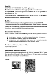
... features, read or download the information on/from the Support\Motherboard\Technology Guide page on how to their respective owners. Check your motherboard looks like this manual may be made by GIGABYTE without GIGABYTE's prior written permission. For example, "REV: 1.0" means the revision of GIGABYTE. The logo is 1.0. Example: by GIGA-BYTE TECHNOLOGY CO., LTD...
... features, read or download the information on/from the Support\Motherboard\Technology Guide page on how to their respective owners. Check your motherboard looks like this manual may be made by GIGABYTE without GIGABYTE's prior written permission. For example, "REV: 1.0" means the revision of GIGABYTE. The logo is 1.0. Example: by GIGA-BYTE TECHNOLOGY CO., LTD...
Manual
Page 4
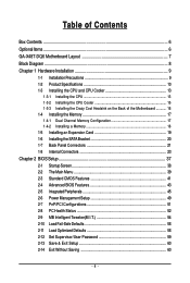
Table of Contents Box Contents ...6 OptionalItems ...6 GA-X48T-DQ6 Motherboard Layout 7 Block Diagram ...8 Chapter 1 Hardware Installation 9 1-1 Installation Precautions 9 1-2 Product Specifications 10 1-3 Installing the CPU and CPU Cooler 13 1-3-1 Installing the CPU 13 1-3-2 Installing the CPU Cooler 15 1-3-3 Installing the Crazy Cool Heatsink on the Back of the Motherboard 16 1-4 Installing the Memory 17 1-4-1 Dual Channel Memory...
Table of Contents Box Contents ...6 OptionalItems ...6 GA-X48T-DQ6 Motherboard Layout 7 Block Diagram ...8 Chapter 1 Hardware Installation 9 1-1 Installation Precautions 9 1-2 Product Specifications 10 1-3 Installing the CPU and CPU Cooler 13 1-3-1 Installing the CPU 13 1-3-2 Installing the CPU Cooler 15 1-3-3 Installing the Crazy Cool Heatsink on the Back of the Motherboard 16 1-4 Installing the Memory 17 1-4-1 Dual Channel Memory...

Manual
Page 6
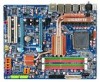
Box Contents GA-X48T-DQ6 motherboard Motherboard driver disk User's Manual Quick Installation Guide Intel® LGA775 CPU Installation Guide One IDE cable and one floppy disk drive cable Four SATA 3Gb/s cables Two SATA brackets I/O Shield Three screws • The box contents above are subject to change without notice. • The motherboard image is for reference...
Box Contents GA-X48T-DQ6 motherboard Motherboard driver disk User's Manual Quick Installation Guide Intel® LGA775 CPU Installation Guide One IDE cable and one floppy disk drive cable Four SATA 3Gb/s cables Two SATA brackets I/O Shield Three screws • The box contents above are subject to change without notice. • The motherboard image is for reference...
Manual
Page 7
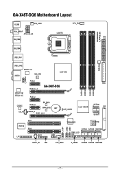
GA-X48T-DQ6 Motherboard Layout KB_MS SYS_FAN1 CPU_FAN RCA_SPDIF ATX_12V_2X LGA775 ATX USB_1394_1 V_PHASE LED USB_1394_2 USB_LAN PWR_FAN USB_LAN2 RTL8111C AUDIO NB_FAN Intel® X48 F_AUDIO RTL8111B/ RTL8111C PCIE_1 PCIE_16_1 GA-X48T-DQ6 PCIE_2 CODEC CD_IN PCIE_3 BP_BIOS MAIN_BIOS BAT SPDIF_O PCIE_16_2 CLR_CMOS FDD DDRIII1 DDRIII2 DDRIII3 DDRIII4 Intel® ICH9R SATAII0 IDE SATAII1 PCI1 IT8718 PCI2 CI COM LPT F_1394 F_USB2 F_USB1 TSB43AB23 GIGABYTE SATA2 SATAII4 SATAII2 GSATAIIA PWR_LED SPDIF_IN TPM SYS_FAN2 F_PANEL SATAII5 SATAII3 GSATAIIB - 7 -
GA-X48T-DQ6 Motherboard Layout KB_MS SYS_FAN1 CPU_FAN RCA_SPDIF ATX_12V_2X LGA775 ATX USB_1394_1 V_PHASE LED USB_1394_2 USB_LAN PWR_FAN USB_LAN2 RTL8111C AUDIO NB_FAN Intel® X48 F_AUDIO RTL8111B/ RTL8111C PCIE_1 PCIE_16_1 GA-X48T-DQ6 PCIE_2 CODEC CD_IN PCIE_3 BP_BIOS MAIN_BIOS BAT SPDIF_O PCIE_16_2 CLR_CMOS FDD DDRIII1 DDRIII2 DDRIII3 DDRIII4 Intel® ICH9R SATAII0 IDE SATAII1 PCI1 IT8718 PCI2 CI COM LPT F_1394 F_USB2 F_USB1 TSB43AB23 GIGABYTE SATA2 SATAII4 SATAII2 GSATAIIA PWR_LED SPDIF_IN TPM SYS_FAN2 F_PANEL SATAII5 SATAII3 GSATAIIB - 7 -
Manual
Page 9
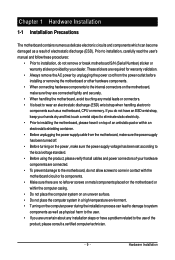
...wrist strap, keep your hands dry and first touch a metal object to eliminate static electricity. • Prior to installing the motherboard, please have it on top of an antistatic pad or within an electrostatic shielding container. • Before unplugging the power supply cable... process can become damaged as a result of electrostatic discharge (ESD). These stickers are connected tightly and securely. • When handling the motherboard, avoid touching any installation steps or have a problem related to the local voltage standard. • Before using the product, please verify ...
...wrist strap, keep your hands dry and first touch a metal object to eliminate static electricity. • Prior to installing the motherboard, please have it on top of an antistatic pad or within an electrostatic shielding container. • Before unplugging the power supply cable... process can become damaged as a result of electrostatic discharge (ESD). These stickers are connected tightly and securely. • When handling the motherboard, avoid touching any installation steps or have a problem related to the local voltage standard. • Before using the product, please verify ...
Manual
Page 10
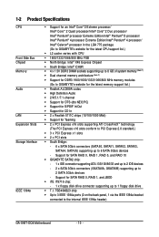
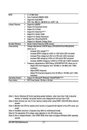
... 1394a bracket connected to 6 SATA 3Gb/s devices - Support for SATA RAID 0, RAID 1, RAID 5, and RAID 10 Š GIGABYTE SATA2 chip: - 1 x IDE connector supporting ATA-133/100/66/33 and up to 2 IDE devices - 2 x SATA ...channel memory architecture (Note 2) Š Support for DDR3 1900/1600/1333/1066/800 MHz memory modules (Go to GIGABYTE's website for the latest memory support list.) Š Realtek ALC889A codec Š High Definition Audio Š 2/4/5.1/7.1-channel...SATAII1, SATAII2, SATAII3, SATAII4, SATAII5) supporting up to the internal IEEE 1394a header) GA-X48T-DQ6 Motherboard - 10 -
... 1394a bracket connected to 6 SATA 3Gb/s devices - Support for SATA RAID 0, RAID 1, RAID 5, and RAID 10 Š GIGABYTE SATA2 chip: - 1 x IDE connector supporting ATA-133/100/66/33 and up to 2 IDE devices - 2 x SATA ...channel memory architecture (Note 2) Š Support for DDR3 1900/1600/1333/1066/800 MHz memory modules (Go to GIGABYTE's website for the latest memory support list.) Š Realtek ALC889A codec Š High Definition Audio Š 2/4/5.1/7.1-channel...SATAII1, SATAII2, SATAII3, SATAII4, SATAII5) supporting up to the internal IEEE 1394a header) GA-X48T-DQ6 Motherboard - 10 -
Manual
Page 12
...in BIOS Setup (CPU/DDR3/PCI-E) allow you to: - Adjust DDR3 frequency - Increase (G)MCH voltage by 0.05V to 0.35V with 0.05V increment - GA-X48T-DQ6 Motherboard - 12 - Adjust CPU host frequency from 90 MHz to 150 MHz with 1 MHz increment Š Support for Dynamic Energy Saver Š Norton Internet...to 1.55V with 0.05V increment - Adjust PCI Express frequency from 100 MHz to 700 MHz with 0.05V increment - Increase DDR3 voltage by motherboard model. (Note 5) The adjustable CPU voltage range depends on the CPU cooler you install. (Note 4) Available functions in BIOS Setup (CPU/...
...in BIOS Setup (CPU/DDR3/PCI-E) allow you to: - Adjust DDR3 frequency - Increase (G)MCH voltage by 0.05V to 0.35V with 0.05V increment - GA-X48T-DQ6 Motherboard - 12 - Adjust CPU host frequency from 90 MHz to 150 MHz with 1 MHz increment Š Support for Dynamic Energy Saver Š Norton Internet...to 1.55V with 0.05V increment - Adjust PCI Express frequency from 100 MHz to 700 MHz with 0.05V increment - Increase DDR3 voltage by motherboard model. (Note 5) The adjustable CPU voltage range depends on the CPU cooler you install. (Note 4) Available functions in BIOS Setup (CPU/...
Manual
Page 13
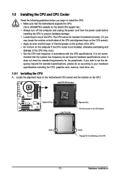
...• Locate the pin one of the CPU Socket Notch Notch Triangle Pin One Marking on the CPU - 13 - mended that the motherboard supports the CPU. (Go to GIGABYTE's website for the peripherals. LGA775 CPU Socket Alignment Key LGA 775 CPU Alignment Key Pin One Corner of the CPU. Locate the alignment... keys on the motherboard CPU socket and the notches on the computer if the CPU cooler is not recom- The CPU cannot ...
...• Locate the pin one of the CPU Socket Notch Notch Triangle Pin One Marking on the CPU - 13 - mended that the motherboard supports the CPU. (Go to GIGABYTE's website for the peripherals. LGA775 CPU Socket Alignment Key LGA 775 CPU Alignment Key Pin One Corner of the CPU. Locate the alignment... keys on the motherboard CPU socket and the notches on the computer if the CPU cooler is not recom- The CPU cannot ...

Manual
Page 14
... one marking (triangle) with the pin one corner of the CPU socket (or you may align the CPU notches with your thumb and index fingers. GA-X48T-DQ6 Motherboard - 14 - Step 3: Lift the metal load plate on the CPU socket. Step 4: Hold the CPU with the socket alignment keys) and gently insert the CPU... raise the CPU socket lever. Step 5: Once the CPU is properly inserted, replace the load plate and push the CPU socket lever back into the motherboard CPU socket.
... one marking (triangle) with the pin one corner of the CPU socket (or you may align the CPU notches with your thumb and index fingers. GA-X48T-DQ6 Motherboard - 14 - Step 3: Lift the metal load plate on the CPU socket. Step 4: Hold the CPU with the socket alignment keys) and gently insert the CPU... raise the CPU socket lever. Step 5: Once the CPU is properly inserted, replace the load plate and push the CPU socket lever back into the motherboard CPU socket.
Manual
Page 15
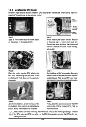
.... If the push pin is inserted as the example cooler.) Step 1: Apply an even and thin layer of thermal grease on the surface of the motherboard. Step 6: Finally, attach the power connector of arrow is to remove the cooler, on the contrary, is complete. Direction of the Arrow Sign on... back of the installed CPU. Check that the Male and Female push pins are joined closely. (Refer to correctly install the CPU cooler on the motherboard. (The following procedure uses Intel® boxed cooler as the picture above, the installation is to the CPU. Use extreme care when removing the...
.... If the push pin is inserted as the example cooler.) Step 1: Apply an even and thin layer of thermal grease on the surface of the motherboard. Step 6: Finally, attach the power connector of arrow is to remove the cooler, on the contrary, is complete. Direction of the Arrow Sign on... back of the installed CPU. Check that the Male and Female push pins are joined closely. (Refer to correctly install the CPU cooler on the motherboard. (The following procedure uses Intel® boxed cooler as the picture above, the installation is to the CPU. Use extreme care when removing the...
Manual
Page 16
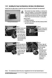
... Step 4: As shown, align the three provided screws with the motherboard. Please prepare: 1. Step 2: Affix the Crazy Cool heatsink to the left) and remove the bolts. GA-X48T-DQ6 Motherboard - 16 - Step 3: On the front side of the motherboard, align the the two bolts removed in Step 1 with the ...nuts on the motherboard and the Crazy Cool heatsink and then tighten the screws to install the ...
... Step 4: As shown, align the three provided screws with the motherboard. Please prepare: 1. Step 2: Affix the Crazy Cool heatsink to the left) and remove the bolts. GA-X48T-DQ6 Motherboard - 16 - Step 3: On the front side of the motherboard, align the the two bolts removed in Step 1 with the ...nuts on the motherboard and the Crazy Cool heatsink and then tighten the screws to install the ...

Manual
Page 17
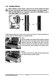
...to install the memory: • Make sure that memory of the same capacity, brand, speed, and chips be used . (Go to GIGABYTE's website for optimum performance. • Each channel can be installed in only one DDR3 memory module is recommended that memory of the same ...DS/SS - - The four DDR3 memory sockets are unable to insert the memory, switch the direction. 1-4-1 Dual Channel Memory Configuration This motherboard provides four DDR3 memory sockets and supports Dual Channel Technology. 1-4 Installing the Memory Read the following guidelines before you are divided into two ...
...to install the memory: • Make sure that memory of the same capacity, brand, speed, and chips be used . (Go to GIGABYTE's website for optimum performance. • Each channel can be installed in only one DDR3 memory module is recommended that memory of the same ...DS/SS - - The four DDR3 memory sockets are unable to insert the memory, switch the direction. 1-4-1 Dual Channel Memory Configuration This motherboard provides four DDR3 memory sockets and supports Dual Channel Technology. 1-4 Installing the Memory Read the following guidelines before you are divided into two ...
Manual
Page 18
... computer and unplug the power cord from the power outlet to prevent damage to install DDR3 DIMMs on this motherboard. Follow the steps below to correctly install your fingers on the socket. GA-X48T-DQ6 Motherboard - 18 - Step 1: Note the orientation of the memory socket. Spread the retaining clips at both ends of the memory...
... computer and unplug the power cord from the power outlet to prevent damage to install DDR3 DIMMs on this motherboard. Follow the steps below to correctly install your fingers on the socket. GA-X48T-DQ6 Motherboard - 18 - Step 1: Note the orientation of the memory socket. Spread the retaining clips at both ends of the memory...
Manual
Page 19
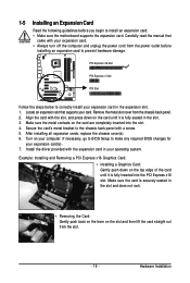
... inserted into the slot. 4. Remove the metal slot cover from the power outlet before you begin to install an expansion card: • Make sure the motherboard supports the expansion card. Example: Installing and Removing a PCI Express x16 Graphics Card: • Installing a Graphics Card: Gently push down on the slot and then...
... inserted into the slot. 4. Remove the metal slot cover from the power outlet before you begin to install an expansion card: • Make sure the motherboard supports the expansion card. Example: Installing and Removing a PCI Express x16 Graphics Card: • Installing a Graphics Card: Gently push down on the slot and then...
Manual
Page 20
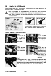
... SATA signal cable, and one free PCI slot and secure the SATA bracket to the chassis back panel with a screw. the external SATA con- GA-X48T-DQ6 Motherboard - 20 - Step 2: Connect the SATA cable from the bracket SATA signal cable into the corresponding connectors when installing. nector on your... motherboard. Then attach the SATA power cable to the power connector on the power supply before installing or removing the SATA bracket and SATA ...
... SATA signal cable, and one free PCI slot and secure the SATA bracket to the chassis back panel with a screw. the external SATA con- GA-X48T-DQ6 Motherboard - 20 - Step 2: Connect the SATA cable from the bracket SATA signal cable into the corresponding connectors when installing. nector on your... motherboard. Then attach the SATA power cable to the power connector on the power supply before installing or removing the SATA bracket and SATA ...
Manual
Page 21
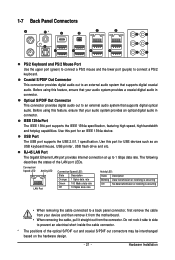
Use this feature, ensure that your device and then remove it from the motherboard. • When removing the cable, pull it side to side to an external audio system that supports digital coaxial audio. Coaxial S/PDIF Out Connector This ...
Use this feature, ensure that your device and then remove it from the motherboard. • When removing the cable, pull it side to side to an external audio system that supports digital coaxial audio. Coaxial S/PDIF Out Connector This ...

Manual
Page 22
... audio software. Line Out Jack (Green) The default line out jack. This jack can be used to connect center/subwoofer speakers in a 5.1/7.1-channel audio configuration. GA-X48T-DQ6 Motherboard - 22 - Center/Subwoofer Speaker Out Jack (Orange) Use this audio jack to connect front speakers in a 4/5.1/7.1-channel audio configuration.
... audio software. Line Out Jack (Green) The default line out jack. This jack can be used to connect center/subwoofer speakers in a 5.1/7.1-channel audio configuration. GA-X48T-DQ6 Motherboard - 22 - Center/Subwoofer Speaker Out Jack (Orange) Use this audio jack to connect front speakers in a 4/5.1/7.1-channel audio configuration.
Manual
Page 23
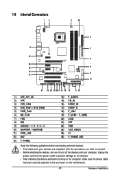
... devices and your devices are compliant with the connectors you wish to connect. • Before installing the devices, be sure to the connector on the motherboard. - 23 - 1-8 Internal Connectors 14 3 25 2 6 7 14 5 23 12 9 15 8 17 11 21 16 22 24 20 4 18 19 13 9 10 1) ATX_12V_2X 2) ATX 3) CPU_FAN 4) SYS_FAN1 / SYS_FAN2...
... devices and your devices are compliant with the connectors you wish to connect. • Before installing the devices, be sure to the connector on the motherboard. - 23 - 1-8 Internal Connectors 14 3 25 2 6 7 14 5 23 12 9 15 8 17 11 21 16 22 24 20 4 18 19 13 9 10 1) ATX_12V_2X 2) ATX 3) CPU_FAN 4) SYS_FAN1 / SYS_FAN2...


