
Manual
Page 1
GA-X38-DQ6 LGA775 socket motherboard for Intel® CoreTM processor family/ Intel® Pentium® processor family/Intel® Celeron® processor family User's Manual Rev. 1002 12ME-X38DQ6-1002R
GA-X38-DQ6 LGA775 socket motherboard for Intel® CoreTM processor family/ Intel® Pentium® processor family/Intel® Celeron® processor family User's Manual Rev. 1002 12ME-X38DQ6-1002R

Manual
Page 2
Motherboard GA-X38-DQ6 Sept. 3, 2007 Motherboard GA-X38-DQ6 Sept. 3, 2007
Motherboard GA-X38-DQ6 Sept. 3, 2007 Motherboard GA-X38-DQ6 Sept. 3, 2007
Manual
Page 3
... manual is protected by copyright laws and is designated by GIGABYTE without GIGABYTE's prior written permission. sive global distributor of GIGABYTE. Documentation Classifications In order to GIGABYTE UNITED INC. For product-related information, check on our website at: http://www.gigabyte.com.tw Identifying Your Motherboard Revision The revision number on our website. The trademarks mentioned...
... manual is protected by copyright laws and is designated by GIGABYTE without GIGABYTE's prior written permission. sive global distributor of GIGABYTE. Documentation Classifications In order to GIGABYTE UNITED INC. For product-related information, check on our website at: http://www.gigabyte.com.tw Identifying Your Motherboard Revision The revision number on our website. The trademarks mentioned...

Manual
Page 4
Table of Contents Box Contents ...6 OptionalItems ...6 GA-X38-DQ6 Motherboard Layout 7 Block Diagram ...8 Chapter 1 Hardware Installation 9 1-1 Installation Precautions 9 1-2 Product Specifications 10 1-3 Installing the CPU and CPU Cooler 13 1-3-1 Installing the CPU 13 1-3-2 Installing the CPU Cooler 15 1-3-3 Removing the Crazy Cool Heatsink from the Back of the Motherboard ..... 16 1-4 Installing the Memory 17 1-4-1 Dual Channel Memory...
Table of Contents Box Contents ...6 OptionalItems ...6 GA-X38-DQ6 Motherboard Layout 7 Block Diagram ...8 Chapter 1 Hardware Installation 9 1-1 Installation Precautions 9 1-2 Product Specifications 10 1-3 Installing the CPU and CPU Cooler 13 1-3-1 Installing the CPU 13 1-3-2 Installing the CPU Cooler 15 1-3-3 Removing the Crazy Cool Heatsink from the Back of the Motherboard ..... 16 1-4 Installing the Memory 17 1-4-1 Dual Channel Memory...
Manual
Page 6
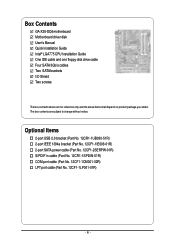
... in cable (Part No. 12CR1-1SPDIN-01R) COM port cable (Part No. 12CF1-1CM001-32R) LPT port cable (Part No. 12CF1-1LP001-01R) - 6 - Box Contents GA-X38-DQ6 motherboard Motherboard driver disk User's Manual Quick Installation Guide Intel® LGA775 CPU Installation Guide One IDE cable and one floppy disk drive cable Four SATA 3Gb...
... in cable (Part No. 12CR1-1SPDIN-01R) COM port cable (Part No. 12CF1-1CM001-32R) LPT port cable (Part No. 12CF1-1LP001-01R) - 6 - Box Contents GA-X38-DQ6 motherboard Motherboard driver disk User's Manual Quick Installation Guide Intel® LGA775 CPU Installation Guide One IDE cable and one floppy disk drive cable Four SATA 3Gb...

Manual
Page 7
GA-X38-DQ6 Motherboard Layout KB_MS RCA_SPDIF USB_1394_1 SYS_FAN1 ATX_12V_2X LGA775 CPU_FAN PCIE_12V ATX USB_1394_2 USB_LAN USB_LAN2 PWR_FAN RTL8111B Intel® X38 AUDIO F_AUDIO PCIE_1 NB_FAN RTL8111B GA-X38-DQ6 FDD PCIE_16_1 DDRII1 DDRII2 DDRII3 DDRII4 CODEC CD_IN PCIE_2 PCIE_3 BP_BIOS MAIN_BIOS BAT PCIE_16_2 CLR_CMOS Intel® ICH9R SATAII0 IDE SATAII1 SPDIF_O PCI1 IT8718 PCI2 LPT CI COM TPM F_1394 F_USB2 F_USB1 TSB43AB23 GIGABYTE SATA2 SATAII4 SATAII2 GSATAIIA PWR_LED SPDIF_IN SYS_FAN2 F_PANEL SATAII5 SATAII3 GSATAIIB - 7 -
GA-X38-DQ6 Motherboard Layout KB_MS RCA_SPDIF USB_1394_1 SYS_FAN1 ATX_12V_2X LGA775 CPU_FAN PCIE_12V ATX USB_1394_2 USB_LAN USB_LAN2 PWR_FAN RTL8111B Intel® X38 AUDIO F_AUDIO PCIE_1 NB_FAN RTL8111B GA-X38-DQ6 FDD PCIE_16_1 DDRII1 DDRII2 DDRII3 DDRII4 CODEC CD_IN PCIE_2 PCIE_3 BP_BIOS MAIN_BIOS BAT PCIE_16_2 CLR_CMOS Intel® ICH9R SATAII0 IDE SATAII1 SPDIF_O PCI1 IT8718 PCI2 LPT CI COM TPM F_1394 F_USB2 F_USB1 TSB43AB23 GIGABYTE SATA2 SATAII4 SATAII2 GSATAIIA PWR_LED SPDIF_IN SYS_FAN2 F_PANEL SATAII5 SATAII3 GSATAIIB - 7 -
Manual
Page 9
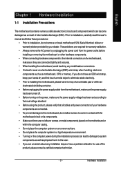
...that all cables and power connectors of electrostatic discharge (ESD). Hardware Installation If you do not allow screws to come in contact with the motherboard circuit or its components. • Make sure there are uncertain about any installation steps or have it on top of an antistatic pad or...strap when handling electronic components such as physical harm to the user. • If you are no leftover screws or metal components placed on the motherboard or within the computer casing. • Do not place the computer system on an uneven surface. • Do not place the computer system ...
...that all cables and power connectors of electrostatic discharge (ESD). Hardware Installation If you do not allow screws to come in contact with the motherboard circuit or its components. • Make sure there are uncertain about any installation steps or have it on top of an antistatic pad or...strap when handling electronic components such as physical harm to the user. • If you are no leftover screws or metal components placed on the motherboard or within the computer casing. • Do not place the computer system on an uneven surface. • Do not place the computer system ...
Manual
Page 10
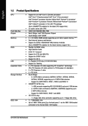
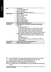
... Š South Bridge: - 6 x SATA 3Gb/s connectors (SATAII0, SATAII1, SATAII2, SATAII3, SATAII4, SATAII5) supporting up to the internal IEEE 1394 header) GA-X38-DQ6 Motherboard - 10 - TSB43AB23 chip Š Up to 3 IEEE 1394a ports (2 on the back panel, 1 via the IEEE 1394 bracket connected to 6 SATA 3Gb... 1 x floppy disk drive connector supporting up to 1 floppy disk drive Š T.I. Support for SATA RAID 0, RAID 1, RAID 5 and RAID 10 Š GIGABYTE SATA2 chip: - 1 x IDE connector supporting ATA-133/100/66/33 and up to 2 IDE devices - 2 x SATA 3 Gb/s connectors (GSATAIIA, GSATAIIB)...
... Š South Bridge: - 6 x SATA 3Gb/s connectors (SATAII0, SATAII1, SATAII2, SATAII3, SATAII4, SATAII5) supporting up to the internal IEEE 1394 header) GA-X38-DQ6 Motherboard - 10 - TSB43AB23 chip Š Up to 3 IEEE 1394a ports (2 on the back panel, 1 via the IEEE 1394 bracket connected to 6 SATA 3Gb... 1 x floppy disk drive connector supporting up to 1 floppy disk drive Š T.I. Support for SATA RAID 0, RAID 1, RAID 5 and RAID 10 Š GIGABYTE SATA2 chip: - 1 x IDE connector supporting ATA-133/100/66/33 and up to 2 IDE devices - 2 x SATA 3 Gb/s connectors (GSATAIIA, GSATAIIB)...
Manual
Page 12
Adjust CPU host frequency from 90 MHz to 150 MHz with 1 MHz increment - GA-X38-DQ6 Motherboard - 12 - Increase PCIe voltage by 0.05V to 0.35V with 0.05V increment - Adjust DDR2 frequency - Adjust PCI Express x16 frequency from 100 MHz to 700 MHz ... size displayed will be less than 4 GB. (Note 2) Available functions in Easytune may differ by 0.05V to 0.35V with 0.05V increment - Increase FSB voltage by motherboard model. (Note 3) The adjustable CPU voltage range depends on the CPU being used. (Note 4) Due to chipset limitation, Intel ICH9R RAID driver does not support...
Adjust CPU host frequency from 90 MHz to 150 MHz with 1 MHz increment - GA-X38-DQ6 Motherboard - 12 - Increase PCIe voltage by 0.05V to 0.35V with 0.05V increment - Adjust DDR2 frequency - Adjust PCI Express x16 frequency from 100 MHz to 700 MHz ... size displayed will be less than 4 GB. (Note 2) Available functions in Easytune may differ by 0.05V to 0.35V with 0.05V increment - Increase FSB voltage by motherboard model. (Note 3) The adjustable CPU voltage range depends on the CPU being used. (Note 4) Due to chipset limitation, Intel ICH9R RAID driver does not support...
Manual
Page 13
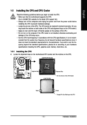
... CPU Socket Alignment Key LGA 775 CPU Alignment Key Pin One Corner of the CPU. mended that the motherboard supports the CPU. (Go to GIGABYTE's website for the peripherals. Locate the alignment keys on the motherboard CPU socket and the notches on the CPU - 13 - Hardware Installation English 1-3 Installing the CPU and CPU...
... CPU Socket Alignment Key LGA 775 CPU Alignment Key Pin One Corner of the CPU. mended that the motherboard supports the CPU. (Go to GIGABYTE's website for the peripherals. Locate the alignment keys on the motherboard CPU socket and the notches on the CPU - 13 - Hardware Installation English 1-3 Installing the CPU and CPU...
Manual
Page 14
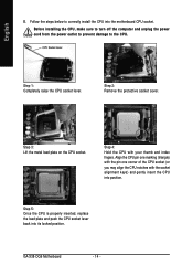
... 2: Remove the protective socket cover. Step 5: Once the CPU is properly inserted, replace the load plate and push the CPU socket lever back into position. GA-X38-DQ6 Motherboard - 14 - English B. Align the CPU pin one marking (triangle) with the pin one corner of the CPU socket (or you may align the CPU notches...
... 2: Remove the protective socket cover. Step 5: Once the CPU is properly inserted, replace the load plate and push the CPU socket lever back into position. GA-X38-DQ6 Motherboard - 14 - English B. Align the CPU pin one marking (triangle) with the pin one corner of the CPU socket (or you may align the CPU notches...

Manual
Page 15
...cooler and CPU may damage the CPU. - 15 - English 1-3-2 Installing the CPU Cooler Follow the steps below to correctly install the CPU cooler on the motherboard. (The following procedure uses Intel® boxed cooler as the picture above, the installation is to install.) Step 3: Place the cooler atop the CPU, ...aligning the four push pins through the pin holes on the motherboard. Push down each push pin. If the push pin is inserted as the example cooler.) Step 1: Apply an even and thin layer of thermal ...
...cooler and CPU may damage the CPU. - 15 - English 1-3-2 Installing the CPU Cooler Follow the steps below to correctly install the CPU cooler on the motherboard. (The following procedure uses Intel® boxed cooler as the picture above, the installation is to install.) Step 3: Place the cooler atop the CPU, ...aligning the four push pins through the pin holes on the motherboard. Push down each push pin. If the push pin is inserted as the example cooler.) Step 1: Apply an even and thin layer of thermal ...

Manual
Page 16
A Philips screwdriver 2. GA-X38-DQ6 Motherboard - 16 - Screws provided with the motherboard from the removal of the board. Step 2: Unfasten ...Step 4: After removing the spring nuts, remove the Crazy Cool heatsink from the back of the motherboard. 1. Always keep the removed screws in appearance from the ones illustrated above. English 1-3-3 Removing the Crazy Cool...mounting holes, follow the steps below to remove the Crazy Cool heatsink from the back of the motherboard. The user shall be responsible for the other screw to complete the removal of the Crazy Cool ...
A Philips screwdriver 2. GA-X38-DQ6 Motherboard - 16 - Screws provided with the motherboard from the removal of the board. Step 2: Unfasten ...Step 4: After removing the spring nuts, remove the Crazy Cool heatsink from the back of the motherboard. 1. Always keep the removed screws in appearance from the ones illustrated above. English 1-3-3 Removing the Crazy Cool...mounting holes, follow the steps below to remove the Crazy Cool heatsink from the back of the motherboard. The user shall be responsible for the other screw to complete the removal of the Crazy Cool ...

Manual
Page 17
...before you are unable to insert the memory, switch the direction. 1-4-1 Dual Channel Memory Configuration This motherboard provides four DDR2 memory sockets and supports Dual Channel Technology. The four DDR2 memory sockets are installed, ... capacity, brand, speed, and chips be installed in only one DDR2 memory module is recommended that the motherboard supports the memory. English 1-4 Installing the Memory Read the following guidelines before installing the memory in Dual ...only one direction. Hardware Installation If you begin to GIGABYTE's website for optimum performance.
...before you are unable to insert the memory, switch the direction. 1-4-1 Dual Channel Memory Configuration This motherboard provides four DDR2 memory sockets and supports Dual Channel Technology. The four DDR2 memory sockets are installed, ... capacity, brand, speed, and chips be installed in only one DDR2 memory module is recommended that the motherboard supports the memory. English 1-4 Installing the Memory Read the following guidelines before installing the memory in Dual ...only one direction. Hardware Installation If you begin to GIGABYTE's website for optimum performance.
Manual
Page 18
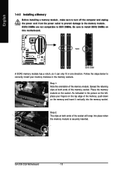
... DDR DIMMs. Be sure to install DDR2 DIMMs on the socket. As indicated in one direction. GA-X38-DQ6 Motherboard - 18 - Spread the retaining clips at both ends of the memory socket. Place the memory module on this motherboard. Follow the steps below to the memory module. English 1-4-2 Installing a Memory Before installing a memory module , make...
... DDR DIMMs. Be sure to install DDR2 DIMMs on the socket. As indicated in one direction. GA-X38-DQ6 Motherboard - 18 - Spread the retaining clips at both ends of the memory socket. Place the memory module on this motherboard. Follow the steps below to the memory module. English 1-4-2 Installing a Memory Before installing a memory module , make...
Manual
Page 19
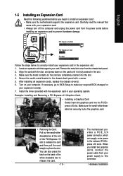
...the Card: Pull out the small whitedrawable bar at the end of the white-drawable bar to release the card. - 19 - • The motherboard provides a PCIE_12V power connector, which can also press the latch on the card are completely inserted into the PCI Express x16 slot. Make sure the...make any required BIOS changes for your operating system. Secure the card's metal bracket to install an expansion card: • Make sure the motherboard supports the expansion card. When you begin to the chassis back panel with the expansion card in the slot. 3. Locate an expansion slot ...
...the Card: Pull out the small whitedrawable bar at the end of the white-drawable bar to release the card. - 19 - • The motherboard provides a PCIE_12V power connector, which can also press the latch on the card are completely inserted into the PCI Express x16 slot. Make sure the...make any required BIOS changes for your operating system. Secure the card's metal bracket to install an expansion card: • Make sure the motherboard supports the expansion card. When you begin to the chassis back panel with the expansion card in the slot. 3. Locate an expansion slot ...
Manual
Page 20
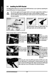
... install the SATA bracket: Step 1: Locate one SATA power cable. Connect the other ends of the external enclosure. the external SATA con- GA-X38-DQ6 Motherboard - 20 - Step 2: Connect the SATA cable from the bracket SATA signal cable into the corresponding connectors when installing. For SATA device in...Step 4: Connect the power Plug one end of the cable from the bracket to the SATA port on the bracket. nector on your motherboard. Before connecting the SATA signal cable, make sure to turn off your system and the power switch on Step 5: the bracket. Then ...
... install the SATA bracket: Step 1: Locate one SATA power cable. Connect the other ends of the external enclosure. the external SATA con- GA-X38-DQ6 Motherboard - 20 - Step 2: Connect the SATA cable from the bracket SATA signal cable into the corresponding connectors when installing. For SATA device in...Step 4: Connect the power Plug one end of the cable from the bracket to the SATA port on the bracket. nector on your motherboard. Before connecting the SATA signal cable, make sure to turn off your system and the power switch on Step 5: the bracket. Then ...
Manual
Page 21
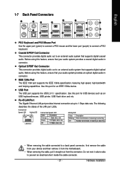
... connector. - 21 - USB Port The USB port supports the USB 2.0/1.1 specification. Before using this feature, ensure that your device and then remove it from the motherboard. • When removing the cable, pull it side to side to an external audio system that supports digital coaxial audio. Use this port for an...
... connector. - 21 - USB Port The USB port supports the USB 2.0/1.1 specification. Before using this feature, ensure that your device and then remove it from the motherboard. • When removing the cable, pull it side to side to an external audio system that supports digital coaxial audio. Use this port for an...
Manual
Page 22
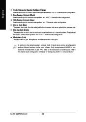
... in a 5.1/7.1-channel audio configuration. In addition to the default speakers settings, the ~ audio jacks can be connected to connect side speakers in a 7.1-channel audio configuration. GA-X38-DQ6 Motherboard - 22 - Rear Speaker Out Jack (Black) Use this audio jack for a headphone or 2-channel speaker. Use this audio jack to the instructions on setting up...
... in a 5.1/7.1-channel audio configuration. In addition to the default speakers settings, the ~ audio jacks can be connected to connect side speakers in a 7.1-channel audio configuration. GA-X38-DQ6 Motherboard - 22 - Rear Speaker Out Jack (Black) Use this audio jack for a headphone or 2-channel speaker. Use this audio jack to the instructions on setting up...
Manual
Page 23
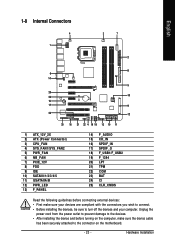
... 18) F_USB1/F_USB2 19) F_1394 20) LPT 21) TPM 22) COM 23) BAT 24) CI 25) CLR_CMOS Read the following guidelines before turning on the motherboard. - 23 - Hardware Installation
... 18) F_USB1/F_USB2 19) F_1394 20) LPT 21) TPM 22) COM 23) BAT 24) CI 25) CLR_CMOS Read the following guidelines before turning on the motherboard. - 23 - Hardware Installation


