Manual
Page 4
......6 GA-P67A-UD3/GA-PH67A-UD3/GA-PH67-UD3 Motherboard Layout 7 GA-P67A-UD3/GA-PH67A-UD3/GA-PH67-UD3 Motherboard Block Diagram 8 Chapter 1 Hardware Installation 9 1-1 Installation Precautions 9 1-2 Product Specifications 10 1-3 Installing the CPU and CPU Cooler 13 1-3-1 Installing the CPU 13 1-3-2 Installing the CPU Cooler 15 1-4 Installing the Memory 16 1-4-1 Dual Channel Memory Configuration 16 1-4-2 Installing a Memory 17 1-5 Installing an Expansion Card 18 1-6 Back Panel Connectors 19 1-7 Internal Connectors 21 Chapter 2 BIOS Setup 29 2-1 Startup Screen 30 2-2 The Main Menu...
......6 GA-P67A-UD3/GA-PH67A-UD3/GA-PH67-UD3 Motherboard Layout 7 GA-P67A-UD3/GA-PH67A-UD3/GA-PH67-UD3 Motherboard Block Diagram 8 Chapter 1 Hardware Installation 9 1-1 Installation Precautions 9 1-2 Product Specifications 10 1-3 Installing the CPU and CPU Cooler 13 1-3-1 Installing the CPU 13 1-3-2 Installing the CPU Cooler 15 1-4 Installing the Memory 16 1-4-1 Dual Channel Memory Configuration 16 1-4-2 Installing a Memory 17 1-5 Installing an Expansion Card 18 1-6 Back Panel Connectors 19 1-7 Internal Connectors 21 Chapter 2 BIOS Setup 29 2-1 Startup Screen 30 2-2 The Main Menu...
Manual
Page 10
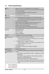
... GA-PH67A-UD3 Only for GA-PH67-UD3 Hardware Installation - 10 - Support for SATA RAID 0, RAID 1, RAID 5, and RAID 10 * When a RAID set is built across the SATA 6Gb/s and SATA 3Gb/s channels, the system performance of physical memory is installed, the actual memory size displayed will be less than 4 GB of the RAID set may vary depending on the devices being con- 1-2 Product Specifications CPU Support for Intel® Core™ i7 processors/Intel® Core™ i5 processors/ Intel® Core...
... GA-PH67A-UD3 Only for GA-PH67-UD3 Hardware Installation - 10 - Support for SATA RAID 0, RAID 1, RAID 5, and RAID 10 * When a RAID set is built across the SATA 6Gb/s and SATA 3Gb/s channels, the system performance of physical memory is installed, the actual memory size displayed will be less than 4 GB of the RAID set may vary depending on the devices being con- 1-2 Product Specifications CPU Support for Intel® Core™ i7 processors/Intel® Core™ i5 processors/ Intel® Core...

Manual
Page 28
... Defaults) or manually configure the BIOS settings (refer to Chapter 2, "BIOS Setup," for a few seconds. Refer to touch the two pins for BIOS configurations). 15) PHASE LED The number of lighted LEDs. date information and BIOS configurations) and reset the CMOS values to clear the CMOS values (e.g. To enable the Phase LED display function, please first enable Dynamic Energy Saver™ 2. Hardware Installation - 28 - 14) CLR_CMOS (Clearing CMOS Jumper) Use this jumper to factory defaults. Open: Normal Short: Clear CMOS Values • Always turn...
... Defaults) or manually configure the BIOS settings (refer to Chapter 2, "BIOS Setup," for a few seconds. Refer to touch the two pins for BIOS configurations). 15) PHASE LED The number of lighted LEDs. date information and BIOS configurations) and reset the CMOS values to clear the CMOS values (e.g. To enable the Phase LED display function, please first enable Dynamic Energy Saver™ 2. Hardware Installation - 28 - 14) CLR_CMOS (Clearing CMOS Jumper) Use this jumper to factory defaults. Open: Normal Short: Clear CMOS Values • Always turn...

Manual
Page 30
Motherboard Model BIOS Version P67A-UD3 F4g . . . . : BIOS Setup : XpressRecovery2 : Boot Menu : Qflash 11/17/2010-P67-7A89UG09C-00 Function Keys Function Keys: : POST SCREEN Press the key to accept. In Boot Menu, use the up hard drive data using the driver disk, the key can access Boot Menu again to change the first boot device setting as needed. : Q-FLASH Press the key to access the Q-Flash utility directly without entering BIOS Setup. BIOS Setup - 30 - The POST Screen Award Modular BIOS v6.00PG Copyright (C) 1984-2010, Award Software, Inc. For more information, refer to ...
Motherboard Model BIOS Version P67A-UD3 F4g . . . . : BIOS Setup : XpressRecovery2 : Boot Menu : Qflash 11/17/2010-P67-7A89UG09C-00 Function Keys Function Keys: : POST SCREEN Press the key to accept. In Boot Menu, use the up hard drive data using the driver disk, the key can access Boot Menu again to change the first boot device setting as needed. : Q-FLASH Press the key to access the Q-Flash utility directly without entering BIOS Setup. BIOS Setup - 30 - The POST Screen Award Modular BIOS v6.00PG Copyright (C) 1984-2010, Award Software, Inc. For more information, refer to ...
Manual
Page 32
..., hard drive types, and the type of errors that stop the system boot, etc. Advanced BIOS Features Use this menu to configure the device boot order, advanced features available on the CPU, and the primary display adapter. Integrated Peripherals Use this menu to configure all peripheral devices, such as SATA, USB, integrated audio, and integrated LAN, etc. Power Management Setup Use this menu to see information about autodetected system/CPU temperature, system voltage and fan speed, etc. Load...
..., hard drive types, and the type of errors that stop the system boot, etc. Advanced BIOS Features Use this menu to configure the device boot order, advanced features available on the CPU, and the primary display adapter. Integrated Peripherals Use this menu to configure all peripheral devices, such as SATA, USB, integrated audio, and integrated LAN, etc. Power Management Setup Use this menu to see information about autodetected system/CPU temperature, system voltage and fan speed, etc. Load...
Manual
Page 35
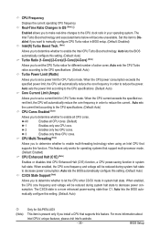
...-threading technology when using an Intel CPU that support multi-processor mode. (Default: Enabled) CPU Enhanced Halt (C1E) (Note) Enables or disables Intel CPU Enhanced Halt (C1E) function, a CPU power-saving function in BIOS setup. (Default: Disabled) Intel(R) Turbo Boost Tech. (Note) Allows you to determine whether to let the CPU enter C3/C6 mode in order to enable the Intel CPU Turbo Boost technology. Set this setting. (Default: Auto) Turbo Ratio (1-Core)/(2-Core)/(3-Core)/(4-Core) (Note) Allows you to decrease power consumption. CPU Frequency Displays...
...-threading technology when using an Intel CPU that support multi-processor mode. (Default: Enabled) CPU Enhanced Halt (C1E) (Note) Enables or disables Intel CPU Enhanced Halt (C1E) function, a CPU power-saving function in BIOS setup. (Default: Disabled) Intel(R) Turbo Boost Tech. (Note) Allows you to determine whether to let the CPU enter C3/C6 mode in order to enable the Intel CPU Turbo Boost technology. Set this setting. (Default: Auto) Turbo Ratio (1-Core)/(2-Core)/(3-Core)/(4-Core) (Note) Allows you to decrease power consumption. CPU Frequency Displays...
Manual
Page 36
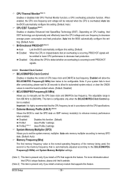
.... Auto lets the BIOS automatically configure this setting. (Default: Auto) Bi-Directional PROCHOT (Note 1) Auto Lets the BIOS automatically configure this setting. (Default) Enabled When the CPU or chipset detects that supports this feature. Note: If your system fails to boot after overclocking, please wait for automated system reboot, or clear the CMOS values to reset the board to emit PROCHOT signals. >>>>> Standard Clock Control BCLK/DMI/PEG Clock Control Enables or disables the control of the memory being used...
.... Auto lets the BIOS automatically configure this setting. (Default: Auto) Bi-Directional PROCHOT (Note 1) Auto Lets the BIOS automatically configure this setting. (Default) Enabled When the CPU or chipset detects that supports this feature. Note: If your system fails to boot after overclocking, please wait for automated system reboot, or clear the CMOS values to reset the board to emit PROCHOT signals. >>>>> Standard Clock Control BCLK/DMI/PEG Clock Control Enables or disables the control of the memory being used...

Manual
Page 39
...Options are: Auto (default), 1~3. >>>>> Channel A/B Misc Timing Control IO Latency Options are : Auto (default), 1~63. QPI/Vtt Voltage The default is Auto. The default is Auto. tFAW Options are : Auto (default), 1~31. Disabled sets the CPU voltage following Intel specifications. (Default: Auto) Note: Enabling Load-Line Calibration may result in damage to Normal. Round Trip Latency Options are: Auto (default), 1~255. Advanced Voltage Settings CMOS Setup Utility-Copyright (C) 1984-2010 Award Software Advanced Voltage Settings ****** Mother Board Voltage Control ****** Voltage...
...Options are: Auto (default), 1~3. >>>>> Channel A/B Misc Timing Control IO Latency Options are : Auto (default), 1~63. QPI/Vtt Voltage The default is Auto. The default is Auto. tFAW Options are : Auto (default), 1~31. Disabled sets the CPU voltage following Intel specifications. (Default: Auto) Note: Enabling Load-Line Calibration may result in damage to Normal. Round Trip Latency Options are: Auto (default), 1~255. Advanced Voltage Settings CMOS Setup Utility-Copyright (C) 1984-2010 Award Software Advanced Voltage Settings ****** Mother Board Voltage Control ****** Voltage...
Manual
Page 40
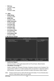
...enable specific streams within the CPU and Chipset. (Default: Enabled) Virtualization Technology (Note) Enables or disables Intel Virtualization Technology. With virtualization, one computer system can function as multiple virtual systems. (Default: Enabled) (Note) This item is Auto. Ch-A Address VRef. PCH Core The default is present only if you install a CPU that supports this feature. Ch-B Data VRef. BIOS Setup - 40 - The default is Auto. CPU PLL The default is Auto. >>> DRAM DRAM Voltage The default is Auto. The default is Auto. DRAM Termination The default is Auto...
...enable specific streams within the CPU and Chipset. (Default: Enabled) Virtualization Technology (Note) Enables or disables Intel Virtualization Technology. With virtualization, one computer system can function as multiple virtual systems. (Default: Enabled) (Note) This item is Auto. Ch-A Address VRef. PCH Core The default is present only if you install a CPU that supports this feature. Ch-B Data VRef. BIOS Setup - 40 - The default is Auto. CPU PLL The default is Auto. >>> DRAM DRAM Voltage The default is Auto. The default is Auto. DRAM Termination The default is Auto...
Manual
Page 43
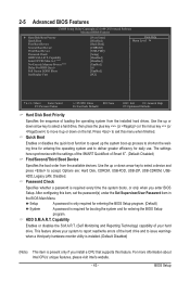
... the BIOS Main Menu. Options are: Hard Disk, CDROM, USB-FDD, USB-ZIP, USB-CDROM, USBHDD, Legacy LAN, Disabled. Capability Enables or disables the S.M.A.R.T. (Self Monitoring and Reporting Technology) capability of your system to report read/write errors of loading the operating system from the available devices. Use the up process to shorten the waiting time for entering the operating system and to issue warnings when a third party hardware monitor utility is installed. (Default: Disabled) (Note...
... the BIOS Main Menu. Options are: Hard Disk, CDROM, USB-FDD, USB-ZIP, USB-CDROM, USBHDD, Legacy LAN, Disabled. Capability Enables or disables the S.M.A.R.T. (Self Monitoring and Reporting Technology) capability of your system to report read/write errors of loading the operating system from the available devices. Use the up process to shorten the waiting time for entering the operating system and to issue warnings when a third party hardware monitor utility is installed. (Default: Disabled) (Note...
Manual
Page 44
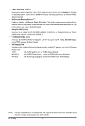
... legacy operating system such as the system boots up. Limit CPUID Max. to 3 (Note) Allows you install a CPU that supports this item to initialize the hard drive as Windows NT4.0. (Default: Disabled) No-Execute Memory Protect (Note) Enables or disables Intel Execute Disable Bit function. set a delay time for the BIOS to Enabled for Windows XP operating system; justable range is present only if you to determine whether to display the GIGABYTE...
... legacy operating system such as the system boots up. Limit CPUID Max. to 3 (Note) Allows you install a CPU that supports this item to initialize the hard drive as Windows NT4.0. (Default: Disabled) No-Execute Memory Protect (Note) Enables or disables Intel Execute Disable Bit function. set a delay time for the BIOS to Enabled for Windows XP operating system; justable range is present only if you to determine whether to display the GIGABYTE...
Manual
Page 45
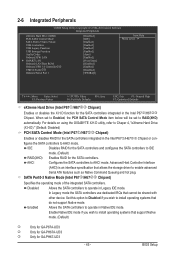
...GA-P67A-UD3 Only for GA-PH67A-UD3 Only for the SATA controllers integrated in Native IDE mode. 2-6 Integrated Peripherals CMOS Setup Utility-Copyright (C) 1984-2010 Award Software Integrated Peripherals eXtreme Hard Drive (XHD) PCH SATA Control Mode SATA Port0-3 Native Mode USB Controllers USB Legacy Function USB Storage Function Azalia Codec Onboard H/W LAN } SMART LAN Onboard LAN Boot ROM Onboard USB 3.0 Controllerjk USB3.0 Turbojk Onboard Serial Port 1 [Disabled] [IDE] [Enabled] [Enabled] [Enabled] [Enabled] [Auto] [Enabled] [Press Enter...
...GA-P67A-UD3 Only for GA-PH67A-UD3 Only for the SATA controllers integrated in Native IDE mode. 2-6 Integrated Peripherals CMOS Setup Utility-Copyright (C) 1984-2010 Award Software Integrated Peripherals eXtreme Hard Drive (XHD) PCH SATA Control Mode SATA Port0-3 Native Mode USB Controllers USB Legacy Function USB Storage Function Azalia Codec Onboard H/W LAN } SMART LAN Onboard LAN Boot ROM Onboard USB 3.0 Controllerjk USB3.0 Turbojk Onboard Serial Port 1 [Disabled] [IDE] [Enabled] [Enabled] [Enabled] [Enabled] [Auto] [Enabled] [Press Enter...
Manual
Page 46
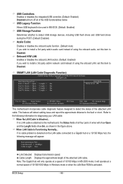
Onboard H/W LAN Enables or disables the onboard LAN function. (Default: Enabled) If you wish to install a 3rd party add-in Windows mode or when the LAN Boot ROM is activated. Link Detected --> 100Mbps Cable Length= 30m Link Detected Displays transmission speed. BIOS Setup - 46 - If no cable problem is attached to the following message will only operate at Port..... Note: The Gigabit hub will appear: Start detecting at a normal speed of 10/100/1000 Mbps...
Onboard H/W LAN Enables or disables the onboard LAN function. (Default: Enabled) If you wish to install a 3rd party add-in Windows mode or when the LAN Boot ROM is activated. Link Detected --> 100Mbps Cable Length= 30m Link Detected Displays transmission speed. BIOS Setup - 46 - If no cable problem is attached to the following message will only operate at Port..... Note: The Gigabit hub will appear: Start detecting at a normal speed of 10/100/1000 Mbps...
Manual
Page 47
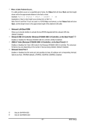
... a Cable Problem Occurs... Options are not used in a 10/100 Mbps environment, so their Status fields will be the approximate distance to activate the boot ROM integrated with the onboard LAN chip. (Default: Disabled) Onboard USB 3.0 Controller (Renesas D720200 USB 3.0 Controller, on the Back Panel)jk Enables or disables the Renesas D720200 USB 3.0 controller. (Default: Enabled) USB3.0 Turbo (Renesas D720200 USB 3.0 Controller, on the Back Panel)jk Enables or disables the Turbo USB mode for GA-PH67A-UD3 - 47 - Example: Part1-2 Status = Short...
... a Cable Problem Occurs... Options are not used in a 10/100 Mbps environment, so their Status fields will be the approximate distance to activate the boot ROM integrated with the onboard LAN chip. (Default: Disabled) Onboard USB 3.0 Controller (Renesas D720200 USB 3.0 Controller, on the Back Panel)jk Enables or disables the Renesas D720200 USB 3.0 controller. (Default: Enabled) USB3.0 Turbo (Renesas D720200 USB 3.0 Controller, on the Back Panel)jk Enables or disables the Turbo USB mode for GA-PH67A-UD3 - 47 - Example: Part1-2 Status = Short...
Manual
Page 51
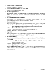
...: Disabled) CPU Smart FAN Control Allows you to emit warning sound if the CPU/system/power fan is set for a 3-pin CPU fan or a 4-pin CPU fan. When CPU temperature exceeds the threshold, BIOS will emit warning sound. CPU/SYSTEM/POWER FAN Fail Warning Allows the system to control the CPU fan speed. PWM Sets PWM mode for a 4-pin CPU fan that is set to control the CPU fan speed under the Slope PWM item. BIOS Setup Auto Lets the BIOS automatically detect the type of CPU fan installed and sets the optimal CPU fan control mode. (Default) Voltage Sets Voltage mode...
...: Disabled) CPU Smart FAN Control Allows you to emit warning sound if the CPU/system/power fan is set for a 3-pin CPU fan or a 4-pin CPU fan. When CPU temperature exceeds the threshold, BIOS will emit warning sound. CPU/SYSTEM/POWER FAN Fail Warning Allows the system to control the CPU fan speed. PWM Sets PWM mode for a 4-pin CPU fan that is set to control the CPU fan speed under the Slope PWM item. BIOS Setup Auto Lets the BIOS automatically detect the type of CPU fan installed and sets the optimal CPU fan control mode. (Default) Voltage Sets Voltage mode...
Manual
Page 63
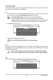
...)DfaotuandEnable HDD 1-0 Loa d CMO S Default Enable Update BIOS from the USB flash drive is saved to a hard drive in RAID/AHCI mode or a hard drive attached to an independent SATA controller, use the key during the POST to update BIOS?" Step 3: When the update process is complete, press any key to return to Drive Enter : Run hi:Move Total size : 0 ESC:Reset Free size : 0 F10:Power Off 3. Step 1: 1. When the message "Are you to save the BIOS file to begin the BIOS update. Q-Flash Utility v2.18 Flash Type/Size MXIC...
...)DfaotuandEnable HDD 1-0 Loa d CMO S Default Enable Update BIOS from the USB flash drive is saved to a hard drive in RAID/AHCI mode or a hard drive attached to an independent SATA controller, use the key during the POST to update BIOS?" Step 3: When the update process is complete, press any key to return to Drive Enter : Run hi:Move Total size : 0 ESC:Reset Free size : 0 F10:Power Off 3. Step 1: 1. When the message "Are you to save the BIOS file to begin the BIOS update. Q-Flash Utility v2.18 Flash Type/Size MXIC...
Manual
Page 75
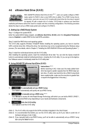
... BIOS Enter the system BIOS Setup program, set up a RAID array: (Note 3) Click Manual to access the Intel Rapid Storage Technology, with a simple click of data. (Note 3) If you manually build a non-RAID 0 array, you can use X.H.D to Chapter 5, "Installing the SATA RAID/AHCI Driver and Operating System." ) Step 3: Install the motherboard drivers and the X.H.D utiltiy After installing the operating system, insert the motherboard driver disk. 4-8 eXtreme Hard Drive (X.H.D) With GIGABYTE eXtreme Hard Drive (X.H.D) (Note 1), users can click the Xpress Install All button...
... BIOS Enter the system BIOS Setup program, set up a RAID array: (Note 3) Click Manual to access the Intel Rapid Storage Technology, with a simple click of data. (Note 3) If you manually build a non-RAID 0 array, you can use X.H.D to Chapter 5, "Installing the SATA RAID/AHCI Driver and Operating System." ) Step 3: Install the motherboard drivers and the X.H.D utiltiy After installing the operating system, insert the motherboard driver disk. 4-8 eXtreme Hard Drive (X.H.D) With GIGABYTE eXtreme Hard Drive (X.H.D) (Note 1), users can click the Xpress Install All button...
Manual
Page 78
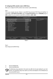
...Configuring SATA controller mode in BIOS Setup Make sure to RAID(XHD) (Figure 1) (IDE by default). CMOS Setup Utility-Copyright (C) 1984-2010 Award Software Integrated Peripherals eXtreme Hard Drive (XHD) PCH SATA Control Mode SATA Port0-3 Native Mode USB Controllers USB Legacy Function USB Storage Function Azalia Codec Onboard H/W LAN } SMART LAN Onboard LAN Boot ROM USB 3.0 Controllerjk USB3.0 Turbojk Onboard Serial Port 1 [Disabled] [RAID(XHD)] [Enabled] [Enabled] [Enabled] [Enabled] [Auto] [Enabled] [Press Enter] [Disabled] [Enabled] [Disabled...
...Configuring SATA controller mode in BIOS Setup Make sure to RAID(XHD) (Figure 1) (IDE by default). CMOS Setup Utility-Copyright (C) 1984-2010 Award Software Integrated Peripherals eXtreme Hard Drive (XHD) PCH SATA Control Mode SATA Port0-3 Native Mode USB Controllers USB Legacy Function USB Storage Function Azalia Codec Onboard H/W LAN } SMART LAN Onboard LAN Boot ROM USB 3.0 Controllerjk USB3.0 Turbojk Onboard Serial Port 1 [Disabled] [RAID(XHD)] [Enabled] [Enabled] [Enabled] [Enabled] [Auto] [Enabled] [Press Enter] [Disabled] [Enabled] [Disabled...
Manual
Page 85
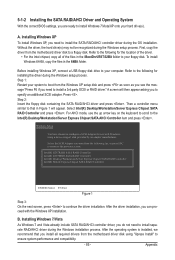
... the location of the files in the \BootDrv\iRST\32Bit folder to your computer. A screen will appear. Refer to the following for installing the driver during the Windows installation process. B. Step 2: Insert the floppy disk containing the SATA RAID/AHCI driver and press . Windows Setup You have chosen to configure a SCSI Adapter for use the up arrow key on the keyboard to scroll to your floppy disk. A. Step 1: Restart your hard drive(s). Then a controller menu...
... the location of the files in the \BootDrv\iRST\32Bit folder to your computer. A screen will appear. Refer to the following for installing the driver during the Windows installation process. B. Step 2: Insert the floppy disk containing the SATA RAID/AHCI driver and press . Windows Setup You have chosen to configure a SCSI Adapter for use the up arrow key on the keyboard to scroll to your floppy disk. A. Step 1: Restart your hard drive(s). Then a controller menu...
Manual
Page 95
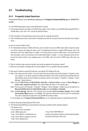
...for "onboard HD audio driver." A: The following Award BIOS beep code descriptions may help you identify possible computer problems. (For reference only.) 1 short: System boots successfully 2 short: CMOS setting error 1 long, 9 short: BIOS ROM error 1 long, 1 short: Memory or motherboard error Continuous long beeps: Graphics card not inserted properly 1 long, 2 short: Monitor or graphics card error Continuous short beeps: Power error 1 long, 3 short: Keyboard error - 95 - Q: What do the beeps emitted during the POST. Appendix You can temporarily remove the battery from Microsoft...
...for "onboard HD audio driver." A: The following Award BIOS beep code descriptions may help you identify possible computer problems. (For reference only.) 1 short: System boots successfully 2 short: CMOS setting error 1 long, 9 short: BIOS ROM error 1 long, 1 short: Memory or motherboard error Continuous long beeps: Graphics card not inserted properly 1 long, 2 short: Monitor or graphics card error Continuous short beeps: Power error 1 long, 3 short: Keyboard error - 95 - Q: What do the beeps emitted during the POST. Appendix You can temporarily remove the battery from Microsoft...


