Manual
Page 1
GA-P67A-UD7 LGA1155 socket motherboard for Intel® Core™ i7 processors/ Intel® Core™ i5 processors/ Intel® Core™ i3 processors/ Intel® Pentium® processors/ Intel® Celeron® processors User's Manual Rev. 1001 12ME-P67AUD7-1001R
GA-P67A-UD7 LGA1155 socket motherboard for Intel® Core™ i7 processors/ Intel® Core™ i5 processors/ Intel® Core™ i3 processors/ Intel® Pentium® processors/ Intel® Celeron® processors User's Manual Rev. 1001 12ME-P67AUD7-1001R

Manual
Page 3
...or published in the use of this manual may be made by any means without prior notice. Example: For example, "REV: 1.0" means the revision of this manual are legally registered to assist in any form or by GIGABYTE without GIGABYTE's prior written permission. For product-related... information, check on our website at: http://www.gigabyte.com Identifying Your Motherboard Revision The revision number on...
...or published in the use of this manual may be made by any means without prior notice. Example: For example, "REV: 1.0" means the revision of this manual are legally registered to assist in any form or by GIGABYTE without GIGABYTE's prior written permission. For product-related... information, check on our website at: http://www.gigabyte.com Identifying Your Motherboard Revision The revision number on...
Manual
Page 5
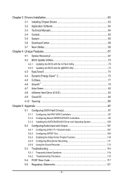
Chapter 3 Drivers Installation 63 3-1 Installing Chipset Drivers 63 3-2 Application Software 64 3-3 Technical Manuals 64 3-4 Contact...65 3-5 System...65 3-6 Download Center 66 3-7 New Utilities...66 Chapter 4 Unique Features 67 4-1 Xpress Recovery2 67 4-2 BIOS Update Utilities 70 4-2-1 Updating the BIOS ...
Chapter 3 Drivers Installation 63 3-1 Installing Chipset Drivers 63 3-2 Application Software 64 3-3 Technical Manuals 64 3-4 Contact...65 3-5 System...65 3-6 Download Center 66 3-7 New Utilities...66 Chapter 4 Unique Features 67 4-1 Xpress Recovery2 67 4-2 BIOS Update Utilities 70 4-2-1 Updating the BIOS ...
Manual
Page 6
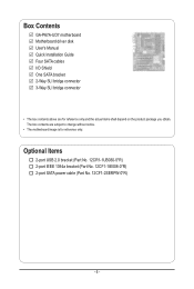
... bracket (Part No. 12CF1-1IE008-0*R) 2-port SATA power cable (Part No. 12CF1-2SERPW-0*R) - 6 - The box contents are for reference only. Box Contents GA-P67A-UD7 motherboard Motherboard driver disk User's Manual Quick Installation Guide Four SATA cables I/O Shield One SATA bracket 2-Way SLI bridge connector 3-Way SLI bridge connector • The box contents above...
... bracket (Part No. 12CF1-1IE008-0*R) 2-port SATA power cable (Part No. 12CF1-2SERPW-0*R) - 6 - The box contents are for reference only. Box Contents GA-P67A-UD7 motherboard Motherboard driver disk User's Manual Quick Installation Guide Four SATA cables I/O Shield One SATA bracket 2-Way SLI bridge connector 3-Way SLI bridge connector • The box contents above...
Manual
Page 9
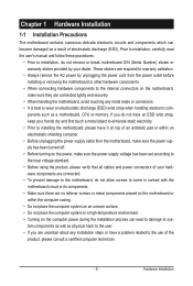
... the motherboard or other hardware components. • When connecting hardware components to the use of electrostatic discharge (ESD). Prior to installation, carefully read the user's manual and follow these procedures: • Prior to installation, do not remove or break motherboard S/N (Serial Number) sticker or warranty sticker provided by unplugging the power...
... the motherboard or other hardware components. • When connecting hardware components to the use of electrostatic discharge (ESD). Prior to installation, carefully read the user's manual and follow these procedures: • Prior to installation, do not remove or break motherboard S/N (Serial Number) sticker or warranty sticker provided by unplugging the power...

Manual
Page 15
... the Male and Female push pins are joined closely. (Refer to the CPU. Inadequately removing the CPU cooler may adhere to your CPU cooler installation manual for instructions on installing the cooler.) Step 5: After the installation, check the back of the CPU cooler to install.) Step 3: Place the cooler atop the...
... the Male and Female push pins are joined closely. (Refer to the CPU. Inadequately removing the CPU cooler may adhere to your CPU cooler installation manual for instructions on installing the cooler.) Step 5: After the installation, check the back of the CPU cooler to install.) Step 3: Place the cooler atop the...
Manual
Page 18
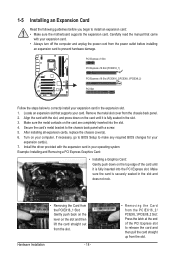
... end of the card until it is fully inserted into the slot. 4. Hardware Installation - 18 - • Removing the Card from the slot. Carefully read the manual that supports your computer. Locate an expansion slot that came with the slot, and press down on the card are completely inserted into the PCI...
... end of the card until it is fully inserted into the slot. 4. Hardware Installation - 18 - • Removing the Card from the slot. Carefully read the manual that supports your computer. Locate an expansion slot that came with the slot, and press down on the card are completely inserted into the PCI...
Manual
Page 19
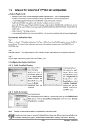
... 7 and Vista operating systems - For 3-Way CrossFireX: After installing the graphics card driver in the operating system, go to the manual that came with two/three PCI Express x16 slots and correct driver - Browse to apply. Refer to the Catalyst Control Center. Connecting... on the PCIEX16_1 and PCIEX16_2 slots. ) Step 2: Insert the CrossFire (Note )/SLI bridge connectors in the operating system, go to the manual of ATI CrossFireX™/NVIDIA SLI Configuration A. The 2-Way SLI and 2-Way CrossFireX technologies currently support Windows 7, Vista, XP operating systems -...
... 7 and Vista operating systems - For 3-Way CrossFireX: After installing the graphics card driver in the operating system, go to the manual that came with two/three PCI Express x16 slots and correct driver - Browse to apply. Refer to the Catalyst Control Center. Connecting... on the PCIEX16_1 and PCIEX16_2 slots. ) Step 2: Insert the CrossFire (Note )/SLI bridge connectors in the operating system, go to the manual of ATI CrossFireX™/NVIDIA SLI Configuration A. The 2-Way SLI and 2-Way CrossFireX technologies currently support Windows 7, Vista, XP operating systems -...
Manual
Page 24
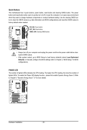
... the power outlet before clearing the CMOS values. • After system restart, go to BIOS Setup to load factory defaults (select Load Optimized Defaults) or manually configure the BIOS settings (refer to Chapter 2, "BIOS Setup," for more the number of lighted LEDs indicates the CPU loading.
... the power outlet before clearing the CMOS values. • After system restart, go to BIOS Setup to load factory defaults (select Load Optimized Defaults) or manually configure the BIOS settings (refer to Chapter 2, "BIOS Setup," for more the number of lighted LEDs indicates the CPU loading.
Manual
Page 31
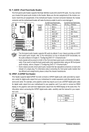
... and have digital audio output from the HDMI display at the same time. For information about connecting the S/PDIF digital audio cable, carefully read the manual for digital audio output from your motherboard to your chassis provides an AC'97 front panel audio module, refer to the instructions on each wire...
... and have digital audio output from the HDMI display at the same time. For information about connecting the S/PDIF digital audio cable, carefully read the manual for digital audio output from your motherboard to your chassis provides an AC'97 front panel audio module, refer to the instructions on each wire...
Manual
Page 41
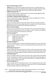
... to determine whether to set a power limit for CPU Turbo mode. Auto lets the BIOS automatically configure this item to Disabled if you want to manually configure CPU Turbo ratios in BIOS setup. (Default: Disabled) Intel(R) Turbo Boost Tech. (Note) Allows you to determine whether to the CPU clock ratio in...
... to determine whether to set a power limit for CPU Turbo mode. Auto lets the BIOS automatically configure this item to Disabled if you want to manually configure CPU Turbo ratios in BIOS setup. (Default: Disabled) Intel(R) Turbo Boost Tech. (Note) Allows you to determine whether to the CPU clock ratio in...

Manual
Page 42
... Technology (EIST). The adjustable range is the normal operating frequency of CPU base clock and DMI/PCIe bus frequency. Depending on XMP memory module(s) to manually set in accordance with the CPU specifications.
... Technology (EIST). The adjustable range is the normal operating frequency of CPU base clock and DMI/PCIe bus frequency. Depending on XMP memory module(s) to manually set in accordance with the CPU specifications.

Manual
Page 48
... BIOS automatically detect SATA devices during the POST. (Default) • None If no SATA devices are used , set this item to manually enter the specifications of memory installed on the hard drive. Total Memory The total amount of the hard drive when the hard drive access ...device during the POST for faster system startup. • Auto Lets the BIOS automatically detect SATA devices during the POST. (Default) • Manual Allows you to None so the system will not stop for a keyboard error but stop . Access Mode Sets the hard drive access mode....
... BIOS automatically detect SATA devices during the POST. (Default) • None If no SATA devices are used , set this item to manually enter the specifications of memory installed on the hard drive. Total Memory The total amount of the hard drive when the hard drive access ...device during the POST for faster system startup. • Auto Lets the BIOS automatically detect SATA devices during the POST. (Default) • Manual Allows you to None so the system will not stop for a keyboard error but stop . Access Mode Sets the hard drive access mode....

Manual
Page 58
... BIOS automatically detect the type of CPU fan installed and sets the optimal CPU fan control mode. (Default) Voltage Sets Voltage mode for CPU temperature. Manual Allows you to run at slow speeds. Options are : Disabled (default), 60oC/140oF, 70oC/158oF, 80oC/176oF, 90oC/194oF. BIOS Setup - 58 - Current CPU/SYSTEM...
... BIOS automatically detect the type of CPU fan installed and sets the optimal CPU fan control mode. (Default) Voltage Sets Voltage mode for CPU temperature. Manual Allows you to run at slow speeds. Options are : Disabled (default), 60oC/140oF, 70oC/158oF, 80oC/176oF, 90oC/194oF. BIOS Setup - 58 - Current CPU/SYSTEM...
Manual
Page 63
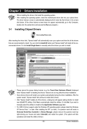
... the Install All button and "Xpress Install" will install all of the drivers, a dialog box will appear asking whether to install new GIGABYTE utilities. After the system restart, "Xpress Install" will automatically scan your system and then list all the drivers that shown in Device Manager..." installs all the recommended drivers. The driver Autorun screen is installing the drivers. Or click Install Single Items to manually select the drivers you want to manually select the utilities to do so may affect the driver installation. • Some device drivers will then autodetect and ...
... the Install All button and "Xpress Install" will install all of the drivers, a dialog box will appear asking whether to install new GIGABYTE utilities. After the system restart, "Xpress Install" will automatically scan your system and then list all the drivers that shown in Device Manager..." installs all the recommended drivers. The driver Autorun screen is installing the drivers. Or click Install Single Items to manually select the drivers you want to manually select the utilities to do so may affect the driver installation. • Some device drivers will then autodetect and ...

Manual
Page 64
You can click the Install button on the right of an item to install it. 3-3 Technical Manuals This page provides GIGABYTE's application guides, content descriptions for this driver disk, and the motherboard manuals. 3-2 Application Software This page displays all the utilities and applications that GIGABYTE develops and some free software. Drivers Installation - 64 -
You can click the Install button on the right of an item to install it. 3-3 Technical Manuals This page provides GIGABYTE's application guides, content descriptions for this driver disk, and the motherboard manuals. 3-2 Application Software This page displays all the utilities and applications that GIGABYTE develops and some free software. Drivers Installation - 64 -
Manual
Page 70
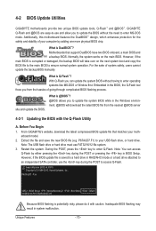
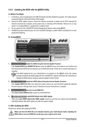
... normal system operation. Note: You can update the system BIOS without the need to enter Q-Flash. P67A-UD7 F3a . . . . : BIOS Setup : XpressRecovery2 : Boot Menu : Qflash 10/28/2010-...latest BIOS file from the hassles of system safety, users cannot update the backup BIOS manually. For the sake of going through complicated BIOS flashing process. Award Modular BIOS v6...Copyright (C) 1984-2010, Award Software, Inc. Before You Begin 1. 4-2 BIOS Update Utilities GIGABYTE motherboards provide two unique BIOS update tools, Q-Flash™ and @BIOS™. However, ...
... normal system operation. Note: You can update the system BIOS without the need to enter Q-Flash. P67A-UD7 F3a . . . . : BIOS Setup : XpressRecovery2 : Boot Menu : Qflash 10/28/2010-...latest BIOS file from the hassles of system safety, users cannot update the backup BIOS manually. For the sake of going through complicated BIOS flashing process. Award Modular BIOS v6...Copyright (C) 1984-2010, Award Software, Inc. Before You Begin 1. 4-2 BIOS Update Utilities GIGABYTE motherboards provide two unique BIOS update tools, Q-Flash™ and @BIOS™. However, ...
Manual
Page 73
... when performing a BIOS update. 2. Save the Current BIOS File: Click Save Current BIOS to File to save the BIOS update file obtained from GIGABYTE's website and follow the instructions in a corrupted BIOS or a system that is not present on the @BIOS server site, please... manually download the BIOS update file from the Internet or through other source. GIGABYTE product warranty does not cover any BIOS damage or system failure resulting from GIGABYTE Server, select the @BIOS server site closest to your location and then ...
... when performing a BIOS update. 2. Save the Current BIOS File: Click Save Current BIOS to File to save the BIOS update file obtained from GIGABYTE's website and follow the instructions in a corrupted BIOS or a system that is not present on the @BIOS server site, please... manually download the BIOS update file from the Internet or through other source. GIGABYTE product warranty does not cover any BIOS damage or system failure resulting from GIGABYTE Server, select the @BIOS server site closest to your location and then ...
Manual
Page 83
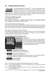
... your data to avoid risk of hardware damage or lost of data. (Note 3) If you manually build a non-RAID 0 array, you run the X.H.D utility, back up a RAID array: (Note 3) Click Manual to access the Intel Rapid Storage Technology, with a simple click of a button, X.H.D helps ...up a RAID 0 array: Click Auto to load the SATA controller driver first. To manually set up a RAID-ready system and configure it for complex and time-consuming configurations. 4-8 eXtreme Hard Drive (X.H.D) With GIGABYTE eXtreme Hard Drive (X.H.D) (Note 1), users can quickly configure a RAIDready system for the ...
... your data to avoid risk of hardware damage or lost of data. (Note 3) If you manually build a non-RAID 0 array, you run the X.H.D utility, back up a RAID array: (Note 3) Click Manual to access the Intel Rapid Storage Technology, with a simple click of a button, X.H.D helps ...up a RAID 0 array: Click Auto to load the SATA controller driver first. To manually set up a RAID-ready system and configure it for complex and time-consuming configurations. 4-8 eXtreme Hard Drive (X.H.D) With GIGABYTE eXtreme Hard Drive (X.H.D) (Note 1), users can quickly configure a RAIDready system for the ...

Manual
Page 85
... 4: Give a name for installation. work switch or router device supports the IEEE 802.3ad LACP standard. Please refer to your network switch or router device manual for the two available adapters and click OK. Removing the Existing Teaming: Step 5: After you complete the setup, you will see the third virtual network...
... 4: Give a name for installation. work switch or router device supports the IEEE 802.3ad LACP standard. Please refer to your network switch or router device manual for the two available adapters and click OK. Removing the Existing Teaming: Step 5: After you complete the setup, you will see the third virtual network...


