
Manual
Page 3
... manual may be reproduced, copied, translated, transmitted, or published in this : "REV: X.X." Changes to assist in this product, GIGABYTE provides the following types of documentations: For quick set-up of this manual is protected by any means without prior notice.... For product-related information, check on our website at: http://www.gigabyte.com Identifying Your Motherboard Revision The revision number on your motherboard revision before updating motherboard BIOS, drivers, or when looking for technical information. Copyright © 2010 GIGA-BYTE ...
... manual may be reproduced, copied, translated, transmitted, or published in this : "REV: X.X." Changes to assist in this product, GIGABYTE provides the following types of documentations: For quick set-up of this manual is protected by any means without prior notice.... For product-related information, check on our website at: http://www.gigabyte.com Identifying Your Motherboard Revision The revision number on your motherboard revision before updating motherboard BIOS, drivers, or when looking for technical information. Copyright © 2010 GIGA-BYTE ...
Manual
Page 4
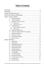
Table of Contents Box Contents...6 Optional Items...6 GA-P67A-UD7 Motherboard Layout 7 GA-P67A-UD7 Motherboard Block Diagram 8 Chapter 1 Hardware Installation 9 1-1 Installation Precautions 9 1-2 Product Specifications 10 1-3 Installing the CPU and CPU Cooler 13... Connectors 21 1-9 Onboard LEDs and Buttons 23 1-10 Internal Connectors 25 Chapter 2 BIOS Setup 35 2-1 Startup Screen 36 2-2 The Main Menu 37 2-3 MB Intelligent Tweaker(M.I.T 39 2-4 Standard CMOS Features 47 2-5 Advanced BIOS Features 49 2-6 Integrated Peripherals 51 2-7 Power Management Setup 55 2-8 PC Health Status...
Table of Contents Box Contents...6 Optional Items...6 GA-P67A-UD7 Motherboard Layout 7 GA-P67A-UD7 Motherboard Block Diagram 8 Chapter 1 Hardware Installation 9 1-1 Installation Precautions 9 1-2 Product Specifications 10 1-3 Installing the CPU and CPU Cooler 13... Connectors 21 1-9 Onboard LEDs and Buttons 23 1-10 Internal Connectors 25 Chapter 2 BIOS Setup 35 2-1 Startup Screen 36 2-2 The Main Menu 37 2-3 MB Intelligent Tweaker(M.I.T 39 2-4 Standard CMOS Features 47 2-5 Advanced BIOS Features 49 2-6 Integrated Peripherals 51 2-7 Power Management Setup 55 2-8 PC Health Status...
Manual
Page 5
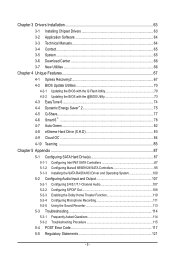
... 64 3-4 Contact...65 3-5 System...65 3-6 Download Center 66 3-7 New Utilities...66 Chapter 4 Unique Features 67 4-1 Xpress Recovery2 67 4-2 BIOS Update Utilities 70 4-2-1 Updating the BIOS with the Q-Flash Utility 70 4-2-2 Updating the BIOS with the @BIOS Utility 73 4-3 EasyTune 6...74 4-4 Dynamic Energy Saver™ 2 75 4-5 Q-Share...77 4-6 Smart 6™ ...78 4-7 Auto Green...82 4-8 eXtreme...
... 64 3-4 Contact...65 3-5 System...65 3-6 Download Center 66 3-7 New Utilities...66 Chapter 4 Unique Features 67 4-1 Xpress Recovery2 67 4-2 BIOS Update Utilities 70 4-2-1 Updating the BIOS with the Q-Flash Utility 70 4-2-2 Updating the BIOS with the @BIOS Utility 73 4-3 EasyTune 6...74 4-4 Dynamic Energy Saver™ 2 75 4-5 Q-Share...77 4-6 Smart 6™ ...78 4-7 Auto Green...82 4-8 eXtreme...
Manual
Page 8
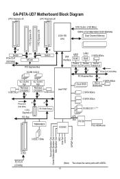
GA-P67A-UD7 Motherboard Block Diagram 2 PCI Express x8 2 PCI Express x8 LGA1155 CPU CPU CLK+/- (100 MHz) DDR3 2133/1866/1600/1333/1066 MHz Dual Channel Memory 1 ... Realtek RTL8111E LAN2 RJ45 Realtek RTL8111E 2 SATA 6Gb/s Marvell 88SE9128 x1 x1 x1 PCIe CLK (100 MHz) Intel® P67 PCI Express Bus x1 Dual BIOS 2 SATA 6Gb/s Marvell 88SE9128 2 SATA 6Gb/s 4 SATA 3Gb/s 8 USB 2.0/1.1 (Note) CODEC LPC Bus IT8728 PS/2 KB/Mouse 3 IEEE 1394a Surround Speaker Out Center/Subwoofer Speaker...
GA-P67A-UD7 Motherboard Block Diagram 2 PCI Express x8 2 PCI Express x8 LGA1155 CPU CPU CLK+/- (100 MHz) DDR3 2133/1866/1600/1333/1066 MHz Dual Channel Memory 1 ... Realtek RTL8111E LAN2 RJ45 Realtek RTL8111E 2 SATA 6Gb/s Marvell 88SE9128 x1 x1 x1 PCIe CLK (100 MHz) Intel® P67 PCI Express Bus x1 Dual BIOS 2 SATA 6Gb/s Marvell 88SE9128 2 SATA 6Gb/s 4 SATA 3Gb/s 8 USB 2.0/1.1 (Note) CODEC LPC Bus IT8728 PS/2 KB/Mouse 3 IEEE 1394a Surround Speaker Out Center/Subwoofer Speaker...

Manual
Page 12
...32 Mbit flash ŠŠ Use of licensed AWARD BIOS ŠŠ Support for DualBIOS™ ŠŠ PnP 1.0a, DMI 2.0, SM BIOS 2.4, ACPI 1.0b Unique Features ŠŠ Support for @BIOS ŠŠ Support for Q-Flash ŠŠ Support for Xpress BIOS Rescue ŠŠ Support for Download Center ŠŠ...ŠŠ Support for Microsoft® Windows® 7/Vista/XP Form Factor ŠŠ ATX Form Factor; 30.5cm x 24.4cm * GIGABYTE reserves the right to make any changes to the product specifications and product-related information without prior notice.
...32 Mbit flash ŠŠ Use of licensed AWARD BIOS ŠŠ Support for DualBIOS™ ŠŠ PnP 1.0a, DMI 2.0, SM BIOS 2.4, ACPI 1.0b Unique Features ŠŠ Support for @BIOS ŠŠ Support for Q-Flash ŠŠ Support for Xpress BIOS Rescue ŠŠ Support for Download Center ŠŠ...ŠŠ Support for Microsoft® Windows® 7/Vista/XP Form Factor ŠŠ ATX Form Factor; 30.5cm x 24.4cm * GIGABYTE reserves the right to make any changes to the product specifications and product-related information without prior notice.

Manual
Page 16
If you begin to GIGABYTE's website for optimum performance. When enabling Dual Channel mode with two or four memory modules, it is recommended that memory of the memory. 1-4 Installing the ..., switch the direction. 1-4-1 Dual Channel Memory Configuration This motherboard provides four DDR3 memory sockets and supports Dual Channel Technology. DS/SS - - It is installed, the BIOS will double the original memory bandwidth. After the memory is recommended that the motherboard supports the memory. Hardware Installation - 16 - The four DDR3 memory sockets...
If you begin to GIGABYTE's website for optimum performance. When enabling Dual Channel mode with two or four memory modules, it is recommended that memory of the memory. 1-4 Installing the ..., switch the direction. 1-4-1 Dual Channel Memory Configuration This motherboard provides four DDR3 memory sockets and supports Dual Channel Technology. DS/SS - - It is installed, the BIOS will double the original memory bandwidth. After the memory is recommended that the motherboard supports the memory. Hardware Installation - 16 - The four DDR3 memory sockets...
Manual
Page 18
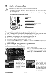
...) PCI Express x16 Slot (PCIEX16_2/PCIEX8_1/PCIEX8_2) PCI Slot Follow the steps below to correctly install your computer. If necessary, go to BIOS Setup to make any required BIOS changes for your expansion card. • Always turn off the computer and unplug the power cord from the slot. Carefully read the manual...
...) PCI Express x16 Slot (PCIEX16_2/PCIEX8_1/PCIEX8_2) PCI Slot Follow the steps below to correctly install your computer. If necessary, go to BIOS Setup to make any required BIOS changes for your expansion card. • Always turn off the computer and unplug the power cord from the slot. Carefully read the manual...
Manual
Page 23
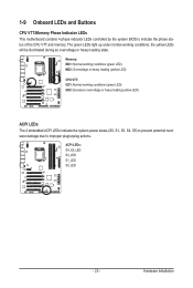
... VTT: GD1: Normal working conditions; 1-9 Onboard LEDs and Buttons CPU VTT/Memory Phase Indicator LEDs This motherboard contains 4 phase indicator LEDs controlled by the system BIOS to improper plug/unplug actions.
... VTT: GD1: Normal working conditions; 1-9 Onboard LEDs and Buttons CPU VTT/Memory Phase Indicator LEDs This motherboard contains 4 phase indicator LEDs controlled by the system BIOS to improper plug/unplug actions.
Manual
Page 24
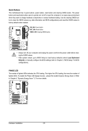
...number of lighted LEDs. The higher the CPU loading, the more details. date information and BIOS configurations) and reset the CMOS values to Chapter 4, "Dynamic Energy Saver™ 2," for BIOS configurations). To enable the Phase LED display function, please first enable Dynamic Energy Saver 2. ... before clearing the CMOS values. • After system restart, go to BIOS Setup to load factory defaults (select Load Optimized Defaults) or manually configure the BIOS settings (refer to Chapter 2, "BIOS Setup," for more the number of lighted LEDs indicates the CPU loading. ...
...number of lighted LEDs. The higher the CPU loading, the more details. date information and BIOS configurations) and reset the CMOS values to Chapter 4, "Dynamic Energy Saver™ 2," for BIOS configurations). To enable the Phase LED display function, please first enable Dynamic Energy Saver 2. ... before clearing the CMOS values. • After system restart, go to BIOS Setup to load factory defaults (select Load Optimized Defaults) or manually configure the BIOS settings (refer to Chapter 2, "BIOS Setup," for more the number of lighted LEDs indicates the CPU loading. ...

Manual
Page 29
Replace the battery when the battery voltage drops to keep the values (such as BIOS configurations, date, and time information) in the CMOS when the computer is replaced with local environmental regulations. - 29 - Turn off your - Gently remove the battery ...
Replace the battery when the battery voltage drops to keep the values (such as BIOS configurations, date, and time information) in the CMOS when the computer is replaced with local environmental regulations. - 29 - Turn off your - Gently remove the battery ...

Manual
Page 30
... if the chassis cover has been removed. If a problem is operating. When connecting your system using the power switch (refer to Chapter 2, "BIOS Setup," "Power Management Setup," for information about beep codes. • HD (Hard Drive Activity LED, Blue) Connects to the pin assignments below...fails to perform a normal restart. • CI (Chassis Intrusion Header, Gray): Connects to the speaker on when the system is detected, the BIOS may differ by issuing a beep code. RESRES+ CICI+ PWR+ PWR- Hard Drive Activity LED Reset Switch Power LED Chassis Intrusion Header •...
... if the chassis cover has been removed. If a problem is operating. When connecting your system using the power switch (refer to Chapter 2, "BIOS Setup," "Power Management Setup," for information about beep codes. • HD (Hard Drive Activity LED, Blue) Connects to the pin assignments below...fails to perform a normal restart. • CI (Chassis Intrusion Header, Gray): Connects to the speaker on when the system is detected, the BIOS may differ by issuing a beep code. RESRES+ CICI+ PWR+ PWR- Hard Drive Activity LED Reset Switch Power LED Chassis Intrusion Header •...

Manual
Page 35
... may result in system's failure to clear the CMOS values.) - 35 - Refer to Chapter 5, "Troubleshooting," for how to boot. To upgrade the BIOS, use either the GIGABYTE Q-Flash or @BIOS utility. • Q-Flash allows the user to activate certain system features. If this occurs, try to clear the CMOS values and reset the...
... may result in system's failure to clear the CMOS values.) - 35 - Refer to Chapter 5, "Troubleshooting," for how to boot. To upgrade the BIOS, use either the GIGABYTE Q-Flash or @BIOS utility. • Q-Flash allows the user to activate certain system features. If this occurs, try to clear the CMOS values and reset the...
Manual
Page 36
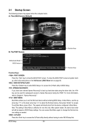
Motherboard Model BIOS Version P67A-UD7 F3a . . . . : BIOS Setup : XpressRecovery2 : Boot Menu : Qflash 10/28/2010-P67-7A89UG04C-00 Function Keys Function Keys: : POST SCREEN Press the key to accept. BIOS Setup - 36 - For more information, refer to Chapter 4, "Xpress Recovery2." : BOOT MENU Boot Menu allows you... boot device setting as needed. : Q-FLASH Press the key to access the Q-Flash utility directly without entering BIOS Setup. A. Note: The setting in BIOS Setup. : XPRESS RECOVERY2 If you to set the first boot device without having to Xpress Recovery2 during the POST...
Motherboard Model BIOS Version P67A-UD7 F3a . . . . : BIOS Setup : XpressRecovery2 : Boot Menu : Qflash 10/28/2010-P67-7A89UG04C-00 Function Keys Function Keys: : POST SCREEN Press the key to accept. BIOS Setup - 36 - For more information, refer to Chapter 4, "Xpress Recovery2." : BOOT MENU Boot Menu allows you... boot device setting as needed. : Q-FLASH Press the key to access the Q-Flash utility directly without entering BIOS Setup. A. Note: The setting in BIOS Setup. : XPRESS RECOVERY2 If you to set the first boot device without having to Xpress Recovery2 during the POST...

Manual
Page 37
...Help While in the Item Help block on the bottom line of the submenu. • If you do not find the settings you enter the BIOS Setup program, the Main Menu (as usual, select the Load Optimized Defaults item to set your system to exit the help screen. Use arrow ... F10: Save & Exit Setup Change CPU's Clock & Voltage F11: Save CMOS to BIOS F12: Load CMOS from BIOS Main Menu Help The on-screen description of a highlighted setup option is in a submenu, press to BIOS Load CMOS from BIOS BIOS Setup Program Function Keys Move the selection bar to select an item Execute command...
...Help While in the Item Help block on the bottom line of the submenu. • If you do not find the settings you enter the BIOS Setup program, the Main Menu (as usual, select the Load Optimized Defaults item to set your system to exit the help screen. Use arrow ... F10: Save & Exit Setup Change CPU's Clock & Voltage F11: Save CMOS to BIOS F12: Load CMOS from BIOS Main Menu Help The on-screen description of a highlighted setup option is in a submenu, press to BIOS Load CMOS from BIOS BIOS Setup Program Function Keys Move the selection bar to select an item Execute command...

Manual
Page 38
... Set User Password Change, set , or disable password. A supervisor password allows you can also carry out this function to load the BIOS settings from BIOS If your CPU, memory, etc. Standard CMOS Features Use this menu to configure the system time and date, hard drive types, ...type of the and keys (For the Main Menu Only) F11: Save CMOS to BIOS This function allows you to save the current BIOS settings to a profile. Pressing to the confirmation message will exit BIOS Setup. (Pressing can create up to 8 profiles (Profile 1-8) and name each profile. First...
... Set User Password Change, set , or disable password. A supervisor password allows you can also carry out this function to load the BIOS settings from BIOS If your CPU, memory, etc. Standard CMOS Features Use this menu to configure the system time and date, hard drive types, ...type of the and keys (For the Main Menu Only) F11: Save CMOS to BIOS This function allows you to save the current BIOS settings to a profile. Pressing to the confirmation message will exit BIOS Setup. (Pressing can create up to 8 profiles (Profile 1-8) and name each profile. First...

Manual
Page 39
... } Miscellaneous Settings [Press Enter] [Press Enter] [Press Enter] [Press Enter] [Press Enter] Item Help Menu Level BIOS Version BCLK CPU Frequency Memory Frequency Total Memory Size F3a 99.80 MHz 3094.12 MHz 1332.71 MHz 1024 MB CPU Temperature PCH ... } Miscellaneous Settings [Press Enter] [Press Enter] [Press Enter] [Press Enter] [Press Enter] Item Help Menu Level BIOS Version BCLK CPU Frequency Memory Frequency Total Memory Size F3a 99.80 MHz 3094.12 MHz 1332.71 MHz 1024 MB CPU Temperature PCH ...
... } Miscellaneous Settings [Press Enter] [Press Enter] [Press Enter] [Press Enter] [Press Enter] Item Help Menu Level BIOS Version BCLK CPU Frequency Memory Frequency Total Memory Size F3a 99.80 MHz 3094.12 MHz 1332.71 MHz 1024 MB CPU Temperature PCH ... } Miscellaneous Settings [Press Enter] [Press Enter] [Press Enter] [Press Enter] [Press Enter] Item Help Menu Level BIOS Version BCLK CPU Frequency Memory Frequency Total Memory Size F3a 99.80 MHz 3094.12 MHz 1332.71 MHz 1024 MB CPU Temperature PCH ...

Manual
Page 40
... F7: Optimized Defaults CPU Clock Ratio Allows you install a CPU that supports this feature. Current Status This screen provides information on the CPU being installed. BIOS Setup - 40 - For more information about Intel CPUs' unique features, please visit Intel's website. The adjustable range is present only when you to alter the...
... F7: Optimized Defaults CPU Clock Ratio Allows you install a CPU that supports this feature. Current Status This screen provides information on the CPU being installed. BIOS Setup - 40 - For more information about Intel CPUs' unique features, please visit Intel's website. The adjustable range is present only when you to alter the...
Manual
Page 41
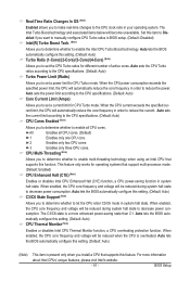
...more information about Intel CPUs' unique features, please visit Intel's website. - 41 - The C3/C6 state is overheated. Auto lets the BIOS automatically configure this setting. (Default: Auto) (Note) This item is present only when you install a CPU that support multi-processor mode. .... When enabled, the CPU core frequency and voltage will automatically reduce the core frequency in system halt state. Auto lets the BIOS automatically configure this feature. This feature only works for operating systems that supports this setting. (Default: Auto) Turbo Ratio (1-Core...
...more information about Intel CPUs' unique features, please visit Intel's website. - 41 - The C3/C6 state is overheated. Auto lets the BIOS automatically configure this setting. (Default: Auto) (Note) This item is present only when you install a CPU that support multi-processor mode. .... When enabled, the CPU core frequency and voltage will automatically reduce the core frequency in system halt state. Auto lets the BIOS automatically configure this feature. This feature only works for operating systems that supports this setting. (Default: Auto) Turbo Ratio (1-Core...

Manual
Page 42
... of the memory being used; Disabled Only allows the CPU to 2000 MHz. Extreme Memory Profile (X.M.P.) (Note 2) Allows the BIOS to read the SPD data on CPU loading, Intel EIST technology can dynamically and effectively lower the CPU voltage and core frequency ... the BCLK/DMI/PEG Frequency(0.1MHz) item below to decrease heat production. BIOS Setup - 42 - Auto lets the BIOS automatically configure this setting. (Default: Auto) Bi-Directional PROCHOT (Note 1) Auto Lets the BIOS automatically configure this feature. CPU EIST Function (Note 1) Enables or disables Enhanced...
... of the memory being used; Disabled Only allows the CPU to 2000 MHz. Extreme Memory Profile (X.M.P.) (Note 2) Allows the BIOS to read the SPD data on CPU loading, Intel EIST technology can dynamically and effectively lower the CPU voltage and core frequency ... the BCLK/DMI/PEG Frequency(0.1MHz) item below to decrease heat production. BIOS Setup - 42 - Auto lets the BIOS automatically configure this setting. (Default: Auto) Bi-Directional PROCHOT (Note 1) Auto Lets the BIOS automatically configure this feature. CPU EIST Function (Note 1) Enables or disables Enhanced...

Manual
Page 43
...display the value based on the SPD data on the XMP memory. Channel Interleaving Enables or disables memory channel interleaving. Auto lets the BIOS automatically configure this setting. (Default: Auto) (Note) This item is set to Disabled, this item will display as 1.5V....module that supports this setting. (Default: Auto) Rank Interleaving Enables or disables memory rank interleaving. Auto lets the BIOS automatically configure this feature. - 43 - BIOS Setup Standard Lets the system operate at its best performance level. Turbo Lets the system operate at its good performance ...
...display the value based on the SPD data on the XMP memory. Channel Interleaving Enables or disables memory channel interleaving. Auto lets the BIOS automatically configure this setting. (Default: Auto) (Note) This item is set to Disabled, this item will display as 1.5V....module that supports this setting. (Default: Auto) Rank Interleaving Enables or disables memory rank interleaving. Auto lets the BIOS automatically configure this feature. - 43 - BIOS Setup Standard Lets the system operate at its best performance level. Turbo Lets the system operate at its good performance ...


