
Manual
Page 5
...; 2 69 4-5 Q-Share...71 4-6 Smart 6™ ...72 4-7 Auto Green...76 4-8 eXtreme Hard Drive (X.H.D 77 4-9 Cloud OC...78 Chapter 5 Appendix...79 5-1 Configuring SATA Hard Drive(s 79 5-1-1 Configuring Intel P67 SATA Controllers 79 5-1-2 Configuring Marvell 88SE9128 SATA Controller 87 5-1-3 Installing the SATA RAID/AHCI Driver and Operating System 92 5-2 Configuring Audio Input and Output 99...
...; 2 69 4-5 Q-Share...71 4-6 Smart 6™ ...72 4-7 Auto Green...76 4-8 eXtreme Hard Drive (X.H.D 77 4-9 Cloud OC...78 Chapter 5 Appendix...79 5-1 Configuring SATA Hard Drive(s 79 5-1-1 Configuring Intel P67 SATA Controllers 79 5-1-2 Configuring Marvell 88SE9128 SATA Controller 87 5-1-3 Installing the SATA RAID/AHCI Driver and Operating System 92 5-2 Configuring Audio Input and Output 99...

Manual
Page 7
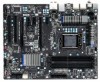
... Marvell 88SE9128 R_USB30 LGA1155 CPU_FAN PHASE LED PWR_FAN USB_LAN Renesas D720200 AUDIO GA-P67A-UD4 ATX F_AUDIO DDR3_1 DDR3_2 DDR3_3 DDR3_4 Realtek RTL8111E PCIEX1_1 (Note) PCIEX16 PCIEX1_2 CODEC PCIEX1_3 BAT SPDIF_O PCIEX8 iTE PCI1 IT8728 PCI2 COMA SYS_FAN2 F_USB3 F_USB2 Intel® P67 iTE IT8892 Bridge F_USB1 Renesas D720200 F_USB30 CLR_CMOS B_BIOS M_BIOS SATA3_1 SATA3_0...
... Marvell 88SE9128 R_USB30 LGA1155 CPU_FAN PHASE LED PWR_FAN USB_LAN Renesas D720200 AUDIO GA-P67A-UD4 ATX F_AUDIO DDR3_1 DDR3_2 DDR3_3 DDR3_4 Realtek RTL8111E PCIEX1_1 (Note) PCIEX16 PCIEX1_2 CODEC PCIEX1_3 BAT SPDIF_O PCIEX8 iTE PCI1 IT8728 PCI2 COMA SYS_FAN2 F_USB3 F_USB2 Intel® P67 iTE IT8892 Bridge F_USB1 Renesas D720200 F_USB30 CLR_CMOS B_BIOS M_BIOS SATA3_1 SATA3_0...

Manual
Page 8
GA-P67A-UD4 Motherboard Block Diagram PCIe CLK (100 MHz) 1 PCI Express x16 or 2 PCI Express x8 LGA1155 CPU CPU CLK+/- (100 MHz) DDR3 2133/1866/1600/1333/... MHz Dual Channel Memory x16 x8 Switch DMI Interface PCI Express Bus 2 SATA 6Gb/s LAN RJ45 Marvell Realtek 88SE9128 RTL8111E PCI Express Bus x1 x1 Intel® P67 PCIe CLK (100 MHz) x1 x1 x1 x1 3 PCI Express x1 iTE IT8892 Bridge PCI Bus CODEC 2 USB 3.0/2.0 2 USB 3.0/2.0 Renesas D720200 Renesas D720200 x1...
GA-P67A-UD4 Motherboard Block Diagram PCIe CLK (100 MHz) 1 PCI Express x16 or 2 PCI Express x8 LGA1155 CPU CPU CLK+/- (100 MHz) DDR3 2133/1866/1600/1333/... MHz Dual Channel Memory x16 x8 Switch DMI Interface PCI Express Bus 2 SATA 6Gb/s LAN RJ45 Marvell Realtek 88SE9128 RTL8111E PCI Express Bus x1 x1 Intel® P67 PCIe CLK (100 MHz) x1 x1 x1 x1 3 PCI Express x1 iTE IT8892 Bridge PCI Bus CODEC 2 USB 3.0/2.0 2 USB 3.0/2.0 Renesas D720200 Renesas D720200 x1...

Manual
Page 10
... in the PCIEX16 slot. 1 x PCI Express x16 slot, running at x8 (PCIEX8) * The PCIEX8 slot shares bandwidth with CPU Intel® P67 Express Chipset Memory Audio 4 x 1.5V DDR3 DIMM sockets supporting up to 2 SATA 6Gb/s devices ...actual memory size displayed will operate at up to x8 mode. 3 x PCI Express x1 slots (All PCI Express slots conform to GIGABYTE's website for S/PDIF Out LAN 1 x Realtek RTL8111E chip (10/100/1000 Mbit) Expansion Slots 1 x PCI ...
... in the PCIEX16 slot. 1 x PCI Express x16 slot, running at x8 (PCIEX8) * The PCIEX8 slot shares bandwidth with CPU Intel® P67 Express Chipset Memory Audio 4 x 1.5V DDR3 DIMM sockets supporting up to 2 SATA 6Gb/s devices ...actual memory size displayed will operate at up to x8 mode. 3 x PCI Express x1 slots (All PCI Express slots conform to GIGABYTE's website for S/PDIF Out LAN 1 x Realtek RTL8111E chip (10/100/1000 Mbit) Expansion Slots 1 x PCI ...

Manual
Page 47
...controllers. Advanced Host Controller Interface (AHCI) is an interface specification that do not support Native mode. SATA Port0-3 Native Mode (Intel P67 Chipset) Specifies the operating mode of the USB functionalities below. Enabled Allows the SATA controllers to operate in MS-DOS. (... automatically. For details on using the GIGABYTE X.H.D utility, refer to Chaper 4, "eXtreme Hard Drive (X.H.D)." (Default: Disabled) PCH SATA Control Mode (Intel P67 Chipset) Enables or disables RAID for the SATA controllers integrated in the Intel P67 Chipset. In Legacy mode the SATA ...
...controllers. Advanced Host Controller Interface (AHCI) is an interface specification that do not support Native mode. SATA Port0-3 Native Mode (Intel P67 Chipset) Specifies the operating mode of the USB functionalities below. Enabled Allows the SATA controllers to operate in MS-DOS. (... automatically. For details on using the GIGABYTE X.H.D utility, refer to Chaper 4, "eXtreme Hard Drive (X.H.D)." (Default: Disabled) PCH SATA Control Mode (Intel P67 Chipset) Enables or disables RAID for the SATA controllers integrated in the Intel P67 Chipset. In Legacy mode the SATA ...

Manual
Page 79
...hard drive. (Note 1) Skip this motherboard, the SATA3_0, SATA3_1 (Note 3), SATA2_2, SATA2_3, SATA2_4 and SATA2_5 ports are supported by the P67 Chipset.) Then connect the power connector from your computer. B. Configure a RAID array in BIOS Setup. Configure SATA controller mode in RAID ... is set may prepare only one hard drive. • Windows 7/Vista/XP setup disk. • Motherboard driver disk. 5-1-1 Configuring Intel P67 SATA Controllers A. Appendix Install SATA hard drive(s) in your computer Attach one SATA controller on your motherboard, refer to "Chapter 1," "Hardware...
...hard drive. (Note 1) Skip this motherboard, the SATA3_0, SATA3_1 (Note 3), SATA2_2, SATA2_3, SATA2_4 and SATA2_5 ports are supported by the P67 Chipset.) Then connect the power connector from your computer. B. Configure a RAID array in BIOS Setup. Configure SATA controller mode in RAID ... is set may prepare only one hard drive. • Windows 7/Vista/XP setup disk. • Motherboard driver disk. 5-1-1 Configuring Intel P67 SATA Controllers A. Appendix Install SATA hard drive(s) in your computer Attach one SATA controller on your motherboard, refer to "Chapter 1," "Hardware...

Manual
Page 92
...XP, connect a USB floppy disk drive to your hard drive(s). Then a controller menu similar to that in the win64 folder. Step 2: For the Intel P67: Insert the floppy disk containing the SATA RAID/AHCI driver and press . To install Windows 64-Bit, copy the files in Figure 1 will then ...are ready to a floppy disk. Windows Setup You have chosen to configure a SCSI Adapter for the location of the driver. • For the Intel P67, copy all of the files in the \BootDrv\Marvell\win32 folder to your floppy disk. 5-1-3 Installing the SATA RAID/AHCI Driver and Operating System ...
...XP, connect a USB floppy disk drive to your hard drive(s). Then a controller menu similar to that in the win64 folder. Step 2: For the Intel P67: Insert the floppy disk containing the SATA RAID/AHCI driver and press . To install Windows 64-Bit, copy the files in Figure 1 will then ...are ready to a floppy disk. Windows Setup You have chosen to configure a SCSI Adapter for the location of the driver. • For the Intel P67, copy all of the files in the \BootDrv\Marvell\win32 folder to your floppy disk. 5-1-3 Installing the SATA RAID/AHCI Driver and Operating System ...

Manual
Page 94
...If you do not enable automatic rebuild on this stage, you have equal or greater capacity than the old one.) For the Intel P67: Turn off your computer. • Enabling Automatic Rebuild Step 1: When the message "Press to enter Configuration Utility" appears, ...The new drive must have to enter the RAID Configuration Utility. Option ROM - 10.0.0.1046 Copyright(C) 2003-10 Intel Corporation. Intel(R) Rapid Storage Technology - Option ROM - 10.0.0.1046 Copyright(C) 2003-10 Intel Corporation. All Rights Reserved. [ MAIN MENU ] 1. Exit a disk initiates a rebuild. The following screen ...
...If you do not enable automatic rebuild on this stage, you have equal or greater capacity than the old one.) For the Intel P67: Turn off your computer. • Enabling Automatic Rebuild Step 1: When the message "Press to enter Configuration Utility" appears, ...The new drive must have to enter the RAID Configuration Utility. Option ROM - 10.0.0.1046 Copyright(C) 2003-10 Intel Corporation. Intel(R) Rapid Storage Technology - Option ROM - 10.0.0.1046 Copyright(C) 2003-10 Intel Corporation. All Rights Reserved. [ MAIN MENU ] 1. Exit a disk initiates a rebuild. The following screen ...


